EP0780867A2 - Vakuum Schaltvorrichtung - Google Patents
Vakuum Schaltvorrichtung Download PDFInfo
- Publication number
- EP0780867A2 EP0780867A2 EP96308888A EP96308888A EP0780867A2 EP 0780867 A2 EP0780867 A2 EP 0780867A2 EP 96308888 A EP96308888 A EP 96308888A EP 96308888 A EP96308888 A EP 96308888A EP 0780867 A2 EP0780867 A2 EP 0780867A2
- Authority
- EP
- European Patent Office
- Prior art keywords
- housing
- stub
- switching
- vacuum
- switching device
- Prior art date
- Legal status (The legal status is an assumption and is not a legal conclusion. Google has not performed a legal analysis and makes no representation as to the accuracy of the status listed.)
- Withdrawn
Links
- 238000005219 brazing Methods 0.000 claims description 17
- 238000000034 method Methods 0.000 claims description 6
- 238000003780 insertion Methods 0.000 claims description 3
- 230000037431 insertion Effects 0.000 claims description 3
- 239000000155 melt Substances 0.000 claims description 3
- 238000010438 heat treatment Methods 0.000 claims description 2
- 239000003795 chemical substances by application Substances 0.000 description 6
- 239000012212 insulator Substances 0.000 description 5
- 239000000919 ceramic Substances 0.000 description 4
- 239000000463 material Substances 0.000 description 4
- RYGMFSIKBFXOCR-UHFFFAOYSA-N Copper Chemical compound [Cu] RYGMFSIKBFXOCR-UHFFFAOYSA-N 0.000 description 3
- 229910052802 copper Inorganic materials 0.000 description 3
- 239000010949 copper Substances 0.000 description 3
- 239000004020 conductor Substances 0.000 description 2
- -1 CrCu Chemical compound 0.000 description 1
- 229910010293 ceramic material Inorganic materials 0.000 description 1
- 230000008021 deposition Effects 0.000 description 1
- 239000002184 metal Substances 0.000 description 1
- 229910052751 metal Inorganic materials 0.000 description 1
- 125000006850 spacer group Chemical group 0.000 description 1
Images
Classifications
-
- H—ELECTRICITY
- H01—ELECTRIC ELEMENTS
- H01H—ELECTRIC SWITCHES; RELAYS; SELECTORS; EMERGENCY PROTECTIVE DEVICES
- H01H33/00—High-tension or heavy-current switches with arc-extinguishing or arc-preventing means
- H01H33/60—Switches wherein the means for extinguishing or preventing the arc do not include separate means for obtaining or increasing flow of arc-extinguishing fluid
- H01H33/66—Vacuum switches
-
- H—ELECTRICITY
- H01—ELECTRIC ELEMENTS
- H01H—ELECTRIC SWITCHES; RELAYS; SELECTORS; EMERGENCY PROTECTIVE DEVICES
- H01H11/00—Apparatus or processes specially adapted for the manufacture of electric switches
-
- H—ELECTRICITY
- H01—ELECTRIC ELEMENTS
- H01H—ELECTRIC SWITCHES; RELAYS; SELECTORS; EMERGENCY PROTECTIVE DEVICES
- H01H33/00—High-tension or heavy-current switches with arc-extinguishing or arc-preventing means
- H01H33/60—Switches wherein the means for extinguishing or preventing the arc do not include separate means for obtaining or increasing flow of arc-extinguishing fluid
- H01H33/66—Vacuum switches
- H01H33/664—Contacts; Arc-extinguishing means, e.g. arcing rings
Definitions
- the invention concerns a vacuum switching device, and in particular, but not exclusively, a vacuum interrupter.
- Vacuum interrupters are commonly used in electrical equipment for interrupting an AC supply in the event of a fault, e.g. a short-circuit on a power line.
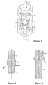
- a typical vacuum interrupter is shown in very general terms in Figure 1.
- the interrupter comprises an insulator 10, normally made of a ceramic material, housing two electrically conductive contacts 11, 12. Contacts 11, 12 are taken out of the interrupter unit by means of respective stems 13, 14, the stems terminating in end-portions 15, 16, normally referred to as "end-stubs", for connection to further electrical equipment (not shown).
- the end-stubs 15, 16 may have external or internal threads for effecting the connections.
- the bellows unit 17 allows axial movement of the stem 14 to make and break, selectively, electrical contact between the contacts 11 and 12, contact 11 and stem 13 being fixed relative to the insulator 10.
- the shield 18 is an electrically conductive component which serves two main purposes: to prevent an arc, which is drawn when the contacts are separated, from striking the insulator and to impede the deposition of metal vapour, which is given off from the contacts when the arc is present, on the insulator.
- a vacuum switching device having a junction at which a housing of said switching device, a first switching component and a second switching component meet, said junction having a vacuum on one side and a gas on the other, said housing and said first and second switching components comprising locating means for allowing accurate location of said first and second switching components with respect to each other and with respect to said housing.
- Said first switching component may comprise a male locating means and said second switching component may comprise a female locating means.
- a hole may be provided in said housing for insertion of said male locating means through said housing, said hole having dimensions such as to allow, at room temperature, a clearance fit between the hole and said male locating means.
- Said first switching component may be a contact member and said second switching component may be an end-stub for the electrical connection of said contact member to external equipment.
- a method of brazing together components of a vacuum switching device comprising an insulating housing arrangement, first and second end-rings disposed at respective ends of said housing arrangement, a first contact member in locating engagement with a first end-stub and with said first end-ring, and a second contact member in locating engagement with a second end-stub and with a bellows assembly, a brazing agent being provided at interfaces of said components to be brazed together, the method comprising:
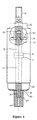
- a vacuum interrupter comprising a pair of contacts 11, 12 on stems 13, 14 with associated end-stubs 15, 16.
- the contact/stem arrangement is housed in a ceramic housing 10, the stem 13 and end-stub 15 being anchored to the ceramic housing 10 by means of an end-ring 23, while the stem 14 and end-stub 16 are anchored to the same housing 10 by way of a bellows unit 60 (only partly shown) and an end-ring 24.
- the stem 13 has been narrowed to form a male locating means 41 in the form of a "peg", while the end-stub 15 has been bored at its upper end to produce a female locating means 42 which receives the peg 41.
- the underside 30 of the end-ring 23 is provided with a hole which accomodates the peg 41 and allows accurate alignment of stem 13 and end-stub 15 along the centre-line of the interrupter.
- the stem 14 is equipped with a narrowed-down portion 43 forming a second peg, while the end-stub 16 is bored at 44 to accomodate the peg 43.
- the two stems 13, 14 have been shown as having the locating pegs, it is also possible for the male and female locating parts to be reversed, so that the end-stubs have the pegs, while the stems are bored to receive them.
- the originally described arrangement of male and female parts is the preferred arrangement.
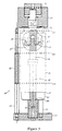
- the interrupter is assembled with the aid of a jig 50, which comprises a base 51, three location rods 52 fixed to the base 51 at equidistant points around its circumference and three location discs 53.
- the lower two discs 53 are maintained at a desired spacing relative to each other by way of spacers 54 (only one of which is shown).
- Assembly is commenced by the insertion of the end-stub 15 of the interrupter into the base 51.
- the fixed end-ring 23 i.e. the end-ring associated with the fixed contact 11
- the fixed conductor arrangement consisting of the contact 11 and the stem 13 is located in the end-stub 15 with the aid of the peg 41.
- the ceramic housing 10 is positioned on top of the end-ring 23, being guided by the lower two location discs 53, and a shield arrangement (not shown) is fitted.
- the moving conductor arrangement consisting of the contact 12 and the stem 14 is then placed on top of the contact 11 and the bellows arrangement fitted, a plate 22 of the bellows arrangement going first, then the end-stub 16 which is located on the peg 43 of the stem 14, then the bellows unit 60 proper, which is held in position by the upper locating ring 53.
- the last component to be fitted is the end-ring 24.
- brazing ring is supplied in series with the components concerned.
- a large weight 55 is placed on top of the end-ring 24 to squeeze the outer joints (e.g. the joint 61 between the ceramic housing 10 and the end-ring 23) and a smaller weight 56 is placed on the end-stub 16 to squeeze the inner joints, including the joint at the junction 45 of the end-stub 16 with the stem 14 and the plate 22 and that at the junction 40 of the end-stub 15 with the stem 13 and the end-ring 23.
- the whole jigged assembly is then placed into an oven, which is evacuated down to 10 -6 mbar and heated to a temperature of up to 800°C, so that the brazing agent melts. The temperature is then allowed to fall, the brazing material then setting and securing all the component parts of the interrupter in one operation.
Landscapes
- High-Tension Arc-Extinguishing Switches Without Spraying Means (AREA)
Applications Claiming Priority (2)
| Application Number | Priority Date | Filing Date | Title |
|---|---|---|---|
| GB9526231 | 1995-12-21 | ||
| GB9526231A GB2308497A (en) | 1995-12-21 | 1995-12-21 | Vacuum switching device |
Publications (2)
| Publication Number | Publication Date |
|---|---|
| EP0780867A2 true EP0780867A2 (de) | 1997-06-25 |
| EP0780867A3 EP0780867A3 (de) | 1998-10-21 |
Family
ID=10785860
Family Applications (1)
| Application Number | Title | Priority Date | Filing Date |
|---|---|---|---|
| EP96308888A Withdrawn EP0780867A3 (de) | 1995-12-21 | 1996-12-06 | Vakuum Schaltvorrichtung |
Country Status (2)
| Country | Link |
|---|---|
| EP (1) | EP0780867A3 (de) |
| GB (1) | GB2308497A (de) |
Cited By (1)
| Publication number | Priority date | Publication date | Assignee | Title |
|---|---|---|---|---|
| CN109585198A (zh) * | 2017-09-28 | 2019-04-05 | 平高集团有限公司 | 一种断路器空间位置对正方法及其对正工装 |
Family Cites Families (7)
| Publication number | Priority date | Publication date | Assignee | Title |
|---|---|---|---|---|
| GB1026054A (en) * | 1962-05-04 | 1966-04-14 | Ass Elect Ind | Improvements relating to vacuum electric devices |
| GB1001425A (en) * | 1963-05-15 | 1965-08-18 | Ass Elect Ind | Improvements relating to vacuum switches |
| GB1107653A (en) * | 1965-04-16 | 1968-03-27 | Gen Electric | Improvements in electric arc control |
| JPS5812230A (ja) * | 1981-07-16 | 1983-01-24 | 富士電機株式会社 | 断路器付真空負荷開閉器 |
| DE3216251A1 (de) * | 1982-04-30 | 1983-11-03 | Siemens AG, 1000 Berlin und 8000 München | Vakuumschaltroehre |
| US4871888A (en) * | 1988-02-16 | 1989-10-03 | Bestel Ernest F | Tubular supported axial magnetic field interrupter |
| US5004877A (en) * | 1988-10-03 | 1991-04-02 | Square D Company | Vacuum interrupter |
-
1995
- 1995-12-21 GB GB9526231A patent/GB2308497A/en not_active Withdrawn
-
1996
- 1996-12-06 EP EP96308888A patent/EP0780867A3/de not_active Withdrawn
Non-Patent Citations (1)
| Title |
|---|
| None |
Cited By (2)
| Publication number | Priority date | Publication date | Assignee | Title |
|---|---|---|---|---|
| CN109585198A (zh) * | 2017-09-28 | 2019-04-05 | 平高集团有限公司 | 一种断路器空间位置对正方法及其对正工装 |
| CN109585198B (zh) * | 2017-09-28 | 2020-05-08 | 平高集团有限公司 | 一种断路器空间位置对正方法及其对正工装 |
Also Published As
| Publication number | Publication date |
|---|---|
| EP0780867A3 (de) | 1998-10-21 |
| GB2308497A (en) | 1997-06-25 |
| GB9526231D0 (en) | 1996-02-21 |
Similar Documents
| Publication | Publication Date | Title |
|---|---|---|
| KR100361390B1 (ko) | 진공차단기,진공차단기용접점코일조립체및원주전극코일의제조방법 | |
| EP3284099B1 (de) | Vakuumschalter, halteklammer dafür und zugehöriges verfahren | |
| CA1158289A (en) | Circuit interrupter | |
| CA1040240A (en) | Electric circuit breaker comprising parallel-connected vacuum interrupters | |
| EP0780867A2 (de) | Vakuum Schaltvorrichtung | |
| KR100972266B1 (ko) | 진공 스위치 기어 | |
| EP0030852B1 (de) | Vakuum-Leistungsschaltvorrichtung | |
| CN1006029B (zh) | 真空断路器的屏蔽装置 | |
| CA1104179A (en) | Arc-shield supporting structure of a vacuum power interrupter | |
| EP0574903B1 (de) | Ultrahochspannungstrenner mit Widerständen | |
| DE60308605T2 (de) | Vakuumschalter | |
| EP0780868B1 (de) | Elektrisch leitender Schirm für einen Vakuumschalter | |
| JP3905266B2 (ja) | 真空絶縁スイッチギヤ | |
| JPS6320036Y2 (de) | ||
| JP7695345B2 (ja) | 焼き嵌め結合を用いた高圧遮断器、および、その高圧遮断器の製造方法 | |
| KR200401664Y1 (ko) | 진공인터럽터의 아크실드 플랜지 | |
| KR830002734Y1 (ko) | 진공개폐장치 | |
| JPS639207Y2 (de) | ||
| JPH02174030A (ja) | 連動ヒューズ | |
| KR200453410Y1 (ko) | 진공 차단기의 진공 인터럽터 | |
| KR20240124340A (ko) | 제거 가능한 코어 핀을 갖는 초고속 이동형 도체 | |
| JPH05314873A (ja) | 投入抵抗付パッファ形ガス遮断器 | |
| JPS6032297B2 (ja) | 真空しや断器 | |
| JPS598261Y2 (ja) | 接触組立体 | |
| JPH01154417A (ja) | 内部導体接続装置を有する密封電気機器 |
Legal Events
| Date | Code | Title | Description |
|---|---|---|---|
| PUAI | Public reference made under article 153(3) epc to a published international application that has entered the european phase |
Free format text: ORIGINAL CODE: 0009012 |
|
| AK | Designated contracting states |
Kind code of ref document: A2 Designated state(s): DE FR GB NL |
|
| PUAL | Search report despatched |
Free format text: ORIGINAL CODE: 0009013 |
|
| AK | Designated contracting states |
Kind code of ref document: A3 Designated state(s): DE FR GB NL |
|
| RAP1 | Party data changed (applicant data changed or rights of an application transferred) |
Owner name: ALSTOM UK LTD |
|
| 17P | Request for examination filed |
Effective date: 19990527 |
|
| STAA | Information on the status of an ep patent application or granted ep patent |
Free format text: STATUS: THE APPLICATION HAS BEEN WITHDRAWN |
|
| 18W | Application withdrawn |
Withdrawal date: 19990817 |