EP0780941A1 - Isolateur colonne avec un interrupteur pour haute tension et au moins un transformateur de mesure - Google Patents
Isolateur colonne avec un interrupteur pour haute tension et au moins un transformateur de mesure Download PDFInfo
- Publication number
- EP0780941A1 EP0780941A1 EP95120383A EP95120383A EP0780941A1 EP 0780941 A1 EP0780941 A1 EP 0780941A1 EP 95120383 A EP95120383 A EP 95120383A EP 95120383 A EP95120383 A EP 95120383A EP 0780941 A1 EP0780941 A1 EP 0780941A1
- Authority
- EP
- European Patent Office
- Prior art keywords
- rod insulator
- tube
- transformer
- interrupter according
- insulator
- Prior art date
- Legal status (The legal status is an assumption and is not a legal conclusion. Google has not performed a legal analysis and makes no representation as to the accuracy of the status listed.)
- Granted
Links
- 239000012212 insulator Substances 0.000 claims abstract description 30
- 238000004804 winding Methods 0.000 claims abstract description 19
- 238000009413 insulation Methods 0.000 claims abstract description 7
- 239000002184 metal Substances 0.000 claims abstract description 6
- 239000004020 conductor Substances 0.000 claims description 2
- 238000001514 detection method Methods 0.000 claims description 2
- 230000001939 inductive effect Effects 0.000 claims description 2
- 238000000926 separation method Methods 0.000 claims description 2
- 230000009466 transformation Effects 0.000 claims description 2
- 230000007246 mechanism Effects 0.000 abstract 1
- 238000000034 method Methods 0.000 description 5
- 238000004519 manufacturing process Methods 0.000 description 4
- 238000010276 construction Methods 0.000 description 3
- 238000009826 distribution Methods 0.000 description 3
- 239000011810 insulating material Substances 0.000 description 3
- 238000001035 drying Methods 0.000 description 2
- 238000005470 impregnation Methods 0.000 description 2
- 239000002985 plastic film Substances 0.000 description 2
- 229920006255 plastic film Polymers 0.000 description 2
- 238000003860 storage Methods 0.000 description 2
- NMFHJNAPXOMSRX-PUPDPRJKSA-N [(1r)-3-(3,4-dimethoxyphenyl)-1-[3-(2-morpholin-4-ylethoxy)phenyl]propyl] (2s)-1-[(2s)-2-(3,4,5-trimethoxyphenyl)butanoyl]piperidine-2-carboxylate Chemical compound C([C@@H](OC(=O)[C@@H]1CCCCN1C(=O)[C@@H](CC)C=1C=C(OC)C(OC)=C(OC)C=1)C=1C=C(OCCN2CCOCC2)C=CC=1)CC1=CC=C(OC)C(OC)=C1 NMFHJNAPXOMSRX-PUPDPRJKSA-N 0.000 description 1
- 238000006243 chemical reaction Methods 0.000 description 1
- 238000006073 displacement reaction Methods 0.000 description 1
- 230000000694 effects Effects 0.000 description 1
- 230000001681 protective effect Effects 0.000 description 1
Images


Classifications
-
- H—ELECTRICITY
- H02—GENERATION; CONVERSION OR DISTRIBUTION OF ELECTRIC POWER
- H02B—BOARDS, SUBSTATIONS OR SWITCHING ARRANGEMENTS FOR THE SUPPLY OR DISTRIBUTION OF ELECTRIC POWER
- H02B13/00—Arrangement of switchgear in which switches are enclosed in, or structurally associated with, a casing, e.g. cubicle
- H02B13/02—Arrangement of switchgear in which switches are enclosed in, or structurally associated with, a casing, e.g. cubicle with metal casing
- H02B13/035—Gas-insulated switchgear
- H02B13/0356—Mounting of monitoring devices, e.g. current transformers
-
- H—ELECTRICITY
- H01—ELECTRIC ELEMENTS
- H01H—ELECTRIC SWITCHES; RELAYS; SELECTORS; EMERGENCY PROTECTIVE DEVICES
- H01H33/00—High-tension or heavy-current switches with arc-extinguishing or arc-preventing means
- H01H33/02—Details
- H01H33/027—Integrated apparatus for measuring current or voltage
Definitions
- the above invention relates to a rod insulator with a high voltage interrupter insulated with the aid of a gas.
- the invention relates to a rod insulator which is provided in a substation and has breakers in SF 6 insulation and measuring transformers.
- an isolator is assigned to each rod insulator, to which current transformers (TA) are assigned and voltage transformers (TV) to measure the electrical current and voltage as well as to supply the protective devices.
- TA current transformers
- TV voltage transformers
- the transformers and the interrupter are mounted on separate brackets, which leads to a considerable space requirement and a large construction effort of the substation.
- the object of the above invention is to avoid the disadvantages of the prior art and to reduce the dimensions and the construction costs for a transformer station AT, using measuring transformers (both TA and TV) which are gas-insulated SF 6 and a current transformer ( TA) and / or have a voltage transformer (TV), the transformer (TA / TV) being installed in the rod insulator, which accommodates an interrupter in SF 6 construction.
- measuring transformers both TA and TV
- TA current transformer
- TV voltage transformer
- the solution proposed according to the invention allows the disadvantages of the prior art, especially one Avoid insulation using oil paper and create the possibility to do without complex winding processes using oil paper or plastic films. Furthermore, no drying processes or impregnation processes taking place under vacuum are required. Furthermore, partial discharges due to the non-uniformity of the layered insulating material are avoided in principle by the invention.
- the manufacturing process is limited to a few assembly processes customary in the industry, which can be carried out together with the assembly of the rod insulator and which enable constant manufacturing processes to be carried out with a minimum of time.
- the performance features and the manufacturing processes for the rod insulator according to the invention essentially correspond to those of the independent transformers TA and TV.
- gaseous insulating material ensures that, due to the mobility and adaptability of the dielectric, the dielectric insulation is also automatically reset in Zones of a non-uniform local course occurs.
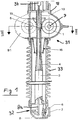
- the rod insulator and breaker (TA) in three components be divided into an interrupter chamber with an interrupter 30, the chamber being only partially shown in the figures, into a zone 31 which receives a current transformer TA and into a housing 32, the means for actuating the movable contacts of the chamber and Has clamps.
- the interrupter chamber has two movable contacts in a known manner, the lower contact 34 being partially shown in the figures. Since the chamber 30 and the movable contacts essentially correspond to the devices of known devices, their detailed representation has been omitted.
- the housing 32 receives a crank 8 for actuating the movable contacts, which can be actuated via a rod 8a which penetrates the insulating body 33.
- the actuation can also take place via a hydraulic cylinder 35, which receives a movable piston 17.
- a Measuring transformer 31 (in the example shown a transformer TA) is provided and designed according to the invention.
- the electromagnetic part TA consists of one or more cores and is arranged inside a toroidal shield 1.
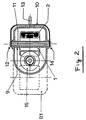
- FIGS. 1 and 2 A single transformer TA is provided in FIGS. 1 and 2 and the position of a possible second transformer, which has a similar structure, is indicated in FIGS. 1 and 2 with dashed lines.
- the secondary windings 2 of the core are grounded via a metal tube 3.
- the metal tube 3 has high rigidity and axially penetrates the rod insulator 33.
- the tube has a rod 4, as well as the lines of the windings, the end pieces of which are sealed by means of insulating bodies 6 from the chamber which receives the insulating gas SF 6 .
- the core 1 is arranged tangentially to the tube 3.
- the metal tube 3 is also held by a fixed insulating tube 19.
- This tube 19 is held at its top by the flange 18.
- the primary winding consists of a conductive tube 9, which is arranged in a horizontal position, and rods 10 and conductor rods 11 are provided, which are inside the tube 9 are arranged.
- the rods 10 are connected to the ends of the tube 9.
- the pipe 9 creates a separation between the inside of the transformer, which receives the gas SF 6 , and the inside of the pipe, which is under atmospheric pressure.
- the primary winding is electrically connected to the housing and thus to the interrupter pole via a switch 12 and is connected to the outer extension 13 (see FIG. 5) via an insulated switchover device 14.
- a voltage distribution system is also proposed both inside and outside the transformer TA. More specifically, an annular shield 15 for distributing the voltage along the insulating rod 5 and the insulating tube 4 is provided, and a tubular shield 16 for distributing the voltage along the insulator 33.
- FIG. 4 shows in section the core 2, which receives a so-called Rogowsky coil 2a, which has a capacitive sensor 36 for simultaneous detection of the current and the voltage.
- FIGS. 1 to 3 show a modified embodiment of the invention, in this drawing the same reference numerals as in FIGS. 1 to 3 have been used to identify identical or corresponding components.
- the main difference from the embodiments according to Figs. 1 to 3 is the arrangement of the tangential core in a horizontal plane, i.e. with arrangement of the axial tube 9 in a vertical arrangement.
- the position of a (possible) second core B2 is illustrated with dashed lines.
- a current transformer (of the type shown in FIGS. 1 to 3 or 5 to 7) is assigned an inductive voltage transformer TV, which is designed in SF 6 insulation, and in FIGS. 8 and 9 with the Reference symbol B3 is identified.
- the part of the transformer B3 connected to ground is mechanically fastened to the position securing tube 3.
- the electromagnetic part of the transformer TV consists of a core 20, on which one or more secondary windings 21 are arranged, which are connected to ground via the metal tube 3 and with the housing of the terminals 7 via insulated passages 6, which are sealed off from the gas SF 6 are connected.
- the primary winding 23 is completely shielded and connected to the live part via a spring 24.
- the shield 22 enables a better distribution of the voltage between the primary part and the secondary part.
Landscapes
- Engineering & Computer Science (AREA)
- Power Engineering (AREA)
- Transformers For Measuring Instruments (AREA)
- Testing Relating To Insulation (AREA)
Priority Applications (5)
| Application Number | Priority Date | Filing Date | Title |
|---|---|---|---|
| AT95120383T ATE179030T1 (de) | 1995-12-22 | 1995-12-22 | Stabisolator mit einem unterbrecher für hochspannung und wenigstens einem messtransformator |
| DE59505666T DE59505666D1 (de) | 1995-12-22 | 1995-12-22 | Stabisolator mit einem Unterbrecher für Hochspannung und wenigstens einem Messtransformator |
| EP95120383A EP0780941B1 (fr) | 1995-12-22 | 1995-12-22 | Isolateur colonne avec un interrupteur pour haute tension et au moins un transformateur de mesure |
| ES95120383T ES2129747T3 (es) | 1995-12-22 | 1995-12-22 | Aislador de columna provisto de un disyuntor para alta tension y con por lo menos un transformador de medicion. |
| GR990401407T GR3030320T3 (en) | 1995-12-22 | 1999-05-27 | Insulating post with a circuit breaker for high voltage and at least one measuring transformer |
Applications Claiming Priority (1)
| Application Number | Priority Date | Filing Date | Title |
|---|---|---|---|
| EP95120383A EP0780941B1 (fr) | 1995-12-22 | 1995-12-22 | Isolateur colonne avec un interrupteur pour haute tension et au moins un transformateur de mesure |
Publications (2)
| Publication Number | Publication Date |
|---|---|
| EP0780941A1 true EP0780941A1 (fr) | 1997-06-25 |
| EP0780941B1 EP0780941B1 (fr) | 1999-04-14 |
Family
ID=8219913
Family Applications (1)
| Application Number | Title | Priority Date | Filing Date |
|---|---|---|---|
| EP95120383A Expired - Lifetime EP0780941B1 (fr) | 1995-12-22 | 1995-12-22 | Isolateur colonne avec un interrupteur pour haute tension et au moins un transformateur de mesure |
Country Status (5)
| Country | Link |
|---|---|
| EP (1) | EP0780941B1 (fr) |
| AT (1) | ATE179030T1 (fr) |
| DE (1) | DE59505666D1 (fr) |
| ES (1) | ES2129747T3 (fr) |
| GR (1) | GR3030320T3 (fr) |
Cited By (3)
| Publication number | Priority date | Publication date | Assignee | Title |
|---|---|---|---|---|
| DE29723039U1 (de) * | 1997-12-22 | 1998-03-12 | Siemens AG, 80333 München | Meß- oder Überwachungseinrichtung für einen Hochspannungsleistungsschalter |
| EP2346128A1 (fr) * | 2010-01-18 | 2011-07-20 | ABB Technology AG | Module de capteur isolé du gaz |
| CN121617809A (zh) * | 2026-02-02 | 2026-03-06 | 天铂互感器(常州)有限公司 | 一种具有抗电磁干扰功能的电流电压互感器 |
Citations (4)
| Publication number | Priority date | Publication date | Assignee | Title |
|---|---|---|---|---|
| GB1112112A (en) * | 1964-07-10 | 1968-05-01 | Reyrolle A & Co Ltd | Improvements relating to isolating switches incorporated in high-voltage gas-filled eectrical insulating bushings |
| GB2083951A (en) * | 1980-09-16 | 1982-03-31 | Gonek S M | High voltage electrical equipment |
| DE3541957A1 (de) * | 1985-03-14 | 1986-09-18 | Sprecher & Schuh AG, Aarau, Aargau | Hochspannungsschaltanlage |
| EP0302391A1 (fr) * | 1987-08-03 | 1989-02-08 | Gec Alsthom Sa | Poste électrique |
-
1995
- 1995-12-22 DE DE59505666T patent/DE59505666D1/de not_active Expired - Lifetime
- 1995-12-22 ES ES95120383T patent/ES2129747T3/es not_active Expired - Lifetime
- 1995-12-22 AT AT95120383T patent/ATE179030T1/de not_active IP Right Cessation
- 1995-12-22 EP EP95120383A patent/EP0780941B1/fr not_active Expired - Lifetime
-
1999
- 1999-05-27 GR GR990401407T patent/GR3030320T3/el unknown
Patent Citations (4)
| Publication number | Priority date | Publication date | Assignee | Title |
|---|---|---|---|---|
| GB1112112A (en) * | 1964-07-10 | 1968-05-01 | Reyrolle A & Co Ltd | Improvements relating to isolating switches incorporated in high-voltage gas-filled eectrical insulating bushings |
| GB2083951A (en) * | 1980-09-16 | 1982-03-31 | Gonek S M | High voltage electrical equipment |
| DE3541957A1 (de) * | 1985-03-14 | 1986-09-18 | Sprecher & Schuh AG, Aarau, Aargau | Hochspannungsschaltanlage |
| EP0302391A1 (fr) * | 1987-08-03 | 1989-02-08 | Gec Alsthom Sa | Poste électrique |
Cited By (4)
| Publication number | Priority date | Publication date | Assignee | Title |
|---|---|---|---|---|
| DE29723039U1 (de) * | 1997-12-22 | 1998-03-12 | Siemens AG, 80333 München | Meß- oder Überwachungseinrichtung für einen Hochspannungsleistungsschalter |
| EP2346128A1 (fr) * | 2010-01-18 | 2011-07-20 | ABB Technology AG | Module de capteur isolé du gaz |
| CN121617809A (zh) * | 2026-02-02 | 2026-03-06 | 天铂互感器(常州)有限公司 | 一种具有抗电磁干扰功能的电流电压互感器 |
| CN121617809B (zh) * | 2026-02-02 | 2026-04-07 | 天铂互感器(常州)有限公司 | 一种具有抗电磁干扰功能的电流电压互感器 |
Also Published As
| Publication number | Publication date |
|---|---|
| GR3030320T3 (en) | 1999-09-30 |
| ES2129747T3 (es) | 1999-06-16 |
| DE59505666D1 (de) | 1999-05-20 |
| ATE179030T1 (de) | 1999-04-15 |
| EP0780941B1 (fr) | 1999-04-14 |
Similar Documents
| Publication | Publication Date | Title |
|---|---|---|
| DE69016967T2 (de) | Hybrid-Mittelspannungsschalter. | |
| EP0291762B1 (fr) | Installation de commutation polyphasée haute tension blindée à isolation gazeuse | |
| EP0744803B1 (fr) | Sectionneur pour une installation de commutation à haute tension, blindé et à isolation gazeuse | |
| DE69728972T2 (de) | Transformator/reactor | |
| DE19511168A1 (de) | Schaltvorrichtung | |
| EP3827457B1 (fr) | Disjoncteur | |
| DE2139225A1 (de) | Gekapselte Hochspannungsanlage mit Druckgas und einem kapazitiven Spannungs teiler | |
| DE1027759B (de) | Metallgekapselte Hochspannungsschaltanlage | |
| DE2037234A1 (de) | Schaltgerat für hohe Spannungen | |
| WO2000045487A1 (fr) | Disjoncteur haute tension encapsule pour courant triphase a construction horizontale | |
| DE3126745A1 (de) | Dreipolige kabelanschlusseinheit fuer eine dreipolige metallgekapselte, druckgasisolierte hochspannungsschaltanlage | |
| DE2929054A1 (de) | Gasisolierte schalteinrichtung | |
| EP0152611B1 (fr) | Appareillage de commutation blindé métallique à gaz isolant | |
| DE2809851C2 (de) | Metallgekapselte mehrphasige Schaltanlage für hohe Spannungen | |
| EP0205397B1 (fr) | Sectionneur pour une installation interrupteur haute tension blindée et isolée au gaz comprimé | |
| DE2644983C2 (de) | Mehrphasige Schalter- und Erderanordnung | |
| EP0780941B1 (fr) | Isolateur colonne avec un interrupteur pour haute tension et au moins un transformateur de mesure | |
| EP0202192B1 (fr) | Installation haute tension blindée à isolation à gaz sous pression | |
| DD295431A5 (de) | Sammelschienenkomponente fuer feststoff-gasisolierte schaltanlagen | |
| DE2458376B2 (de) | Hochspannungs-leistungsschalter | |
| DE3148142A1 (de) | "vakuumschalter" | |
| DE3732455C2 (fr) | ||
| DE1665637B2 (de) | Druckgasisolierte hochspannungsschaltanlage | |
| EP3979278B1 (fr) | Module de transformateur de courant pour une installation de commutation et installation de commutation correspondante | |
| EP0054726A2 (fr) | Dispositif pour la mise à terre des conducteurs d'une installation de commutation blindée et pour le test des cables connectés à ladite installation |
Legal Events
| Date | Code | Title | Description |
|---|---|---|---|
| PUAI | Public reference made under article 153(3) epc to a published international application that has entered the european phase |
Free format text: ORIGINAL CODE: 0009012 |
|
| AK | Designated contracting states |
Kind code of ref document: A1 Designated state(s): AT BE CH DE DK ES FR GB GR IE IT LI LU NL PT SE |
|
| 17P | Request for examination filed |
Effective date: 19971114 |
|
| GRAG | Despatch of communication of intention to grant |
Free format text: ORIGINAL CODE: EPIDOS AGRA |
|
| 17Q | First examination report despatched |
Effective date: 19980602 |
|
| GRAG | Despatch of communication of intention to grant |
Free format text: ORIGINAL CODE: EPIDOS AGRA |
|
| GRAH | Despatch of communication of intention to grant a patent |
Free format text: ORIGINAL CODE: EPIDOS IGRA |
|
| GRAH | Despatch of communication of intention to grant a patent |
Free format text: ORIGINAL CODE: EPIDOS IGRA |
|
| GRAA | (expected) grant |
Free format text: ORIGINAL CODE: 0009210 |
|
| AK | Designated contracting states |
Kind code of ref document: B1 Designated state(s): AT BE CH DE DK ES FR GB GR IE IT LI LU NL PT SE |
|
| PG25 | Lapsed in a contracting state [announced via postgrant information from national office to epo] |
Ref country code: SE Free format text: THE PATENT HAS BEEN ANNULLED BY A DECISION OF A NATIONAL AUTHORITY Effective date: 19990414 Ref country code: GB Free format text: LAPSE BECAUSE OF NON-PAYMENT OF DUE FEES Effective date: 19990414 Ref country code: FR Free format text: LAPSE BECAUSE OF FAILURE TO SUBMIT A TRANSLATION OF THE DESCRIPTION OR TO PAY THE FEE WITHIN THE PRESCRIBED TIME-LIMIT Effective date: 19990414 |
|
| REF | Corresponds to: |
Ref document number: 179030 Country of ref document: AT Date of ref document: 19990415 Kind code of ref document: T |
|
| REG | Reference to a national code |
Ref country code: CH Ref legal event code: EP |
|
| REG | Reference to a national code |
Ref country code: CH Ref legal event code: NV Representative=s name: ROTTMANN, ZIMMERMANN + PARTNER AG |
|
| REG | Reference to a national code |
Ref country code: IE Ref legal event code: FG4D Free format text: GERMAN |
|
| REF | Corresponds to: |
Ref document number: 59505666 Country of ref document: DE Date of ref document: 19990520 |
|
| REG | Reference to a national code |
Ref country code: ES Ref legal event code: FG2A Ref document number: 2129747 Country of ref document: ES Kind code of ref document: T3 |
|
| PG25 | Lapsed in a contracting state [announced via postgrant information from national office to epo] |
Ref country code: PT Free format text: LAPSE BECAUSE OF FAILURE TO SUBMIT A TRANSLATION OF THE DESCRIPTION OR TO PAY THE FEE WITHIN THE PRESCRIBED TIME-LIMIT Effective date: 19990714 Ref country code: DK Free format text: LAPSE BECAUSE OF FAILURE TO SUBMIT A TRANSLATION OF THE DESCRIPTION OR TO PAY THE FEE WITHIN THE PRESCRIBED TIME-LIMIT Effective date: 19990714 |
|
| EN | Fr: translation not filed | ||
| GBV | Gb: ep patent (uk) treated as always having been void in accordance with gb section 77(7)/1977 [no translation filed] |
Effective date: 19990414 |
|
| PG25 | Lapsed in a contracting state [announced via postgrant information from national office to epo] |
Ref country code: IE Free format text: LAPSE BECAUSE OF NON-PAYMENT OF DUE FEES Effective date: 19991206 |
|
| PG25 | Lapsed in a contracting state [announced via postgrant information from national office to epo] |
Ref country code: LU Free format text: LAPSE BECAUSE OF NON-PAYMENT OF DUE FEES Effective date: 19991222 Ref country code: AT Free format text: LAPSE BECAUSE OF NON-PAYMENT OF DUE FEES Effective date: 19991222 |
|
| PG25 | Lapsed in a contracting state [announced via postgrant information from national office to epo] |
Ref country code: BE Free format text: LAPSE BECAUSE OF NON-PAYMENT OF DUE FEES Effective date: 19991231 |
|
| REG | Reference to a national code |
Ref country code: IE Ref legal event code: FD4D |
|
| PLBE | No opposition filed within time limit |
Free format text: ORIGINAL CODE: 0009261 |
|
| STAA | Information on the status of an ep patent application or granted ep patent |
Free format text: STATUS: NO OPPOSITION FILED WITHIN TIME LIMIT |
|
| 26N | No opposition filed | ||
| BERE | Be: lapsed |
Owner name: ABB ADDA S.P.A. Effective date: 19991231 |
|
| PGFP | Annual fee paid to national office [announced via postgrant information from national office to epo] |
Ref country code: NL Payment date: 20051214 Year of fee payment: 11 |
|
| PGFP | Annual fee paid to national office [announced via postgrant information from national office to epo] |
Ref country code: ES Payment date: 20051215 Year of fee payment: 11 Ref country code: CH Payment date: 20051215 Year of fee payment: 11 |
|
| PGFP | Annual fee paid to national office [announced via postgrant information from national office to epo] |
Ref country code: GR Payment date: 20051221 Year of fee payment: 11 |
|
| PG25 | Lapsed in a contracting state [announced via postgrant information from national office to epo] |
Ref country code: LI Free format text: LAPSE BECAUSE OF NON-PAYMENT OF DUE FEES Effective date: 20061231 Ref country code: CH Free format text: LAPSE BECAUSE OF NON-PAYMENT OF DUE FEES Effective date: 20061231 |
|
| PG25 | Lapsed in a contracting state [announced via postgrant information from national office to epo] |
Ref country code: NL Free format text: LAPSE BECAUSE OF NON-PAYMENT OF DUE FEES Effective date: 20070701 |
|
| REG | Reference to a national code |
Ref country code: CH Ref legal event code: PL |
|
| NLV4 | Nl: lapsed or anulled due to non-payment of the annual fee |
Effective date: 20070701 |
|
| REG | Reference to a national code |
Ref country code: ES Ref legal event code: FD2A Effective date: 20061223 |
|
| PG25 | Lapsed in a contracting state [announced via postgrant information from national office to epo] |
Ref country code: ES Free format text: LAPSE BECAUSE OF NON-PAYMENT OF DUE FEES Effective date: 20061223 |
|
| PG25 | Lapsed in a contracting state [announced via postgrant information from national office to epo] |
Ref country code: GR Free format text: LAPSE BECAUSE OF NON-PAYMENT OF DUE FEES Effective date: 20070704 |
|
| PGFP | Annual fee paid to national office [announced via postgrant information from national office to epo] |
Ref country code: DE Payment date: 20141211 Year of fee payment: 20 |
|
| PGFP | Annual fee paid to national office [announced via postgrant information from national office to epo] |
Ref country code: IT Payment date: 20141222 Year of fee payment: 20 |
|
| REG | Reference to a national code |
Ref country code: DE Ref legal event code: R082 Ref document number: 59505666 Country of ref document: DE Representative=s name: SCHAUMBURG & PARTNER PATENTANWAELTE MBB, DE Ref country code: DE Ref legal event code: R082 Ref document number: 59505666 Country of ref document: DE Representative=s name: SCHAUMBURG & PARTNER PATENTANWAELTE GBR, DE |
|
| REG | Reference to a national code |
Ref country code: DE Ref legal event code: R071 Ref document number: 59505666 Country of ref document: DE |