EP2346128A1 - Module de capteur isolé du gaz - Google Patents
Module de capteur isolé du gaz Download PDFInfo
- Publication number
- EP2346128A1 EP2346128A1 EP10194252A EP10194252A EP2346128A1 EP 2346128 A1 EP2346128 A1 EP 2346128A1 EP 10194252 A EP10194252 A EP 10194252A EP 10194252 A EP10194252 A EP 10194252A EP 2346128 A1 EP2346128 A1 EP 2346128A1
- Authority
- EP
- European Patent Office
- Prior art keywords
- housing
- measuring unit
- voltage measuring
- primary
- voltage
- Prior art date
- Legal status (The legal status is an assumption and is not a legal conclusion. Google has not performed a legal analysis and makes no representation as to the accuracy of the status listed.)
- Granted
Links
Images


Classifications
-
- H—ELECTRICITY
- H02—GENERATION; CONVERSION OR DISTRIBUTION OF ELECTRIC POWER
- H02B—BOARDS, SUBSTATIONS OR SWITCHING ARRANGEMENTS FOR THE SUPPLY OR DISTRIBUTION OF ELECTRIC POWER
- H02B13/00—Arrangement of switchgear in which switches are enclosed in, or structurally associated with, a casing, e.g. cubicle
- H02B13/02—Arrangement of switchgear in which switches are enclosed in, or structurally associated with, a casing, e.g. cubicle with metal casing
- H02B13/035—Gas-insulated switchgear
- H02B13/0356—Mounting of monitoring devices, e.g. current transformers
-
- H—ELECTRICITY
- H01—ELECTRIC ELEMENTS
- H01F—MAGNETS; INDUCTANCES; TRANSFORMERS; SELECTION OF MATERIALS FOR THEIR MAGNETIC PROPERTIES
- H01F38/00—Adaptations of transformers or inductances for specific applications or functions
- H01F38/20—Instruments transformers
- H01F38/22—Instruments transformers for single phase AC
- H01F38/24—Voltage transformers
-
- H—ELECTRICITY
- H01—ELECTRIC ELEMENTS
- H01H—ELECTRIC SWITCHES; RELAYS; SELECTORS; EMERGENCY PROTECTIVE DEVICES
- H01H33/00—High-tension or heavy-current switches with arc-extinguishing or arc-preventing means
Definitions
- the present invention relates to a component of a gas-insulated high-voltage switchgear, also called GIS, in particular a gas-insulated high-voltage converter.
- GIS gas-insulated high-voltage switchgear
- Such generic high voltage modules are used to detect voltages to primary conductors in a GIS switchgear.
- the voltages of the phase conductors which are at different electrical potentials, typically in a gas-insulated high-voltage sensor, also referred to as voltage converter, determined separately for all phases together or in each case a gas-insulated high-voltage converter per phase.
- the phase conductors in the region of the high-voltage sensors have conductor stubs extending transversely to the conductor axis, which open into a connection region at the connection flange of the corresponding encapsulated housing of the GIS switchgear.
- the voltage measuring unit with the at least one voltage transformer typically has three primary phase connections extending parallel to one another, which are each connected to a voltage transformer for measuring the respective primary voltage.
- the primary phase connections are connected to the connection area of the conductor stubs during assembly of the voltage measurement unit.
- the metal-encapsulated housing of the voltage measuring unit is filled with insulating gas, for example sulfur hexafluoride.
- both the three primary phase terminals, as well as the actual corresponding measuring unit per phase are encapsulated together in a gas space.
- the three parallel aligned primary phase terminals are arranged in an isosceles triangle to each other to realize an optimal connection geometry.
- a representative of the first type is for example in the EP 0603619 A1 disclosed.
- each primary phase connection as well as the actual corresponding measurement unit for each phase is encapsulated in a separate gas space.
- typically three identical voltage transformers are used.
- a GIS requires higher electrical power with a constant shielding gas and a consistent functional design and consistent materials, this generally has a negative effect on the dimensions of the GIS, since the GIS can be made less compact due to increased housing diameters or dimensions.
- the gas-insulated high-voltage measuring unit has at least two parallel to each other extending arranged primary phase terminals, which is connected to at least one associated measuring unit for measuring a primary voltage of the primary phase terminals.
- the primary phase terminals and the measuring units are encapsulated in a housing of the high-voltage measuring unit.
- the housing of the high-voltage measuring unit according to the invention has, per primary phase connection, in each case a separate housing-side connection opening, which encompasses the respective primary phase connection and, depending on the embodiment, opens, for example, into a flange-like adapter section of the housing.
- the at least two primary phase terminals are arranged in a common plane in such a way that the housing has an elongated housing cross section in a sectional plane running perpendicular to this plane whose length (housing length) is greater than its width (housing width).
- the primary phase terminals and the measuring units are arranged together encapsulated in a gas space of the housing.
- each housing-side connection opening is used for separate recording of a single primary phase connection.
- the term 'single-phase insulator' is understood to mean an electrical insulator through which only a nominal conductor (a primary phase) is guided.
- the common gas space of the high-voltage measuring unit is designed, for example, by a flange-like adapter section through housing ribs in the manner of three single-phase encapsulated primary phase terminals, wherein the resulting gas chambers on a flange adapter portion facing away from the end of the high-voltage measuring unit open hydraulically into a single gas space.
- the flange adapter section serves as a mechanical contact surface for mechanical fastening with a connection module, for example.
- This basic embodiment has several advantages compared to a multiphase or multiple single-phase high-voltage measuring units.
- the high voltage measurement unit requires only a single filling with insulating gas.
- a second advantage resides in the fact that the high-voltage measuring unit can already be completely pre-assembled as a pre-assembly unit, since the gas-tight insulation of the high-voltage measuring unit can be completely realized before the commissioning phase.
- the high-voltage measuring unit requires only a single monitoring of the protective gas / insulating gas in the common gas space of the high-voltage measuring unit during operation.
- Fourth, the multi-phase encapsulation of the primary phase terminals allows a relatively relatively close arrangement of two adjacent primary phase terminals of different electrical potential. This not least allows an improvement in the degree of freedom for the construction of the high-voltage measuring unit.
- the common arrangement of the primary phase connections in a common gas space allows optimization of the mass of the housing of the high-voltage measuring unit.
- the gas space of the high-voltage measuring unit is designed as a pressure vessel which is designed for operation at a nominal pressure of at least 2.5 bar (250,000 Pa) in the respective gas space, a GIS high-voltage module can thus be realized.
- the high-voltage measuring unit is subsequently filled with a pressurized insulating gas, such as sulfur hexafluoride or the like, which, depending on the intended voltage level, is for example below 2, 6 or more bar pressure.
- Absolute pressure is understood to mean the pressure difference between the pressure / gas pressure inside the gas space and outside the gas space.
- this structure comprises at least one structural element extending in the direction of the primary connections, for example in the form of a rib of the housing.
- ribs can typically be produced economically.
- a housing produced by casting is in one preferred embodiment of the high-voltage measuring unit in one or two parts.
- this is formed by at least one of the absolute pressure in the gas space counteracting structure by a local recess of the housing.
- the local indentation of the housing takes place by an indentation of the width and / or the length of the housing.
- the at least one structure protrudes into the interior of the housing.
- Such an embodiment is for example advantageous if protruding parts should be avoided or if the structure should be protected from external damage.
- housing is ribbed in at least one section of the primary-side connection region between the primary phase connections. This applies in particular if the two housing flanks are connected to one another in the section of the primary-side connection region via at least one rib.
- a particularly low gas volume can be achieved with high-voltage measuring units in which the primary phase connections and / or the measuring units are arranged in a form-fitting manner in one another.
- the term 'form-fittingly interlocked' is understood to mean a geometric orientation or orientation of the primary phase connections and / or the measuring units relative to one another.
- the measuring units as a voltage converter, each having an iron core and a winding package, the measuring unit has, seen in the direction of the primary phase connection, a cross-shaped cross section in the region of the measuring unit.
- An interlocking of two adjacent measuring units can be achieved by a rotation of the measuring units about the respective longitudinal axis of the primary phase connections by an angle of inclination and a subsequent pushing against each other in the direction of the housing length.
- a further reduction of the gas volume can be achieved if the housing cross-section in the direction of the housing length and / or in the direction of the primary phase connections at least in sections follows a common envelope of the measuring units and / or the primary phase connections.
- At least one of the primary connections in the primary-side connection region is connected to a dry plug-in contact coupling. It when all primary phase terminals are connected via a plug-in contact coupling, such as in the form of a dry plug-in contact coupling is particularly advantageous.
- the plug-in connection is designed as a dry plug-in connection, this makes it possible to connect the high-voltage measuring unit to the adjacent module (connection module) without requiring an insulating gas manipulation, such as evacuation of the gas volume of the high-voltage measuring unit or the adjacent module.
- this embodiment enables an economical repair and (re) commissioning process.
- the term dry plug connection is understood to mean an electrically insulating plug connection which enables high-voltage insulation in the ambient air.
- the primary terminal contact or contact terminal of the dry plug-in connection is electrically opposite to typically housing located at ground potential isolated a solid insulator.
- a high-voltage insulator made of a ductile, insulating material such as silicone fits snugly against the solid insulator and / or the contact connection.
- the required gas-tightness of the connection between the high-voltage measuring unit and the connection module is ensured by means of seals inserted in the adapter section or in the connection region of the plug-in connection.
- the ductile insulation material largely displaces the ambient air from the plug-in coupling.
- the construction volume and / or the gas volume of the high-voltage measuring unit can be further reduced if the dry plug-in contact coupling comprises an at least partially integrated electrical insulator.
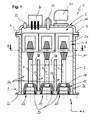
- the longitudinal section through a first embodiment of two three-phase encapsulated HV-GIS modules in uncoupled state of FIG. 1 shows a gas-insulated high-voltage measuring unit 1, which is connected to an adjacent module, not shown, hereinafter also called second module, connectable.
- the high-voltage measuring unit is designed as a voltage converter, while the adjacent module, for example, represents a connection module in a gas-insulated switchgear panel.
- the high-voltage measuring unit 1 has a one-piece, sleeve-like housing 3, which is frontally closed or closed in a gastight manner by means of a screw connection 4, which is illustrated in a stylized manner, with a cover 2.
- housing is understood to mean in the following generally the entire housing structure with housing 3 and cover 2, which limits a common gas space.
- the housing 3 comprises three nominal conductor connections 5, 6, 7, also called phase conductors or primary phase connections, which are connected to corresponding measuring units 8 in the form of measuring transducers.
- the extending in the Z direction phase conductors 5, 6, 7 of the high-voltage measuring unit can be electrically connected to each other with corresponding phase conductors of different potential of the second module via one connector 9 per phase.
- the electrical connection of the phase conductors 5, 6, 7 of the high-voltage measuring unit with the phase conductors of the second module 2 is carried out exclusively via the connectors 9.
- the primary phase terminals 5, 6, 7 of the high-voltage measuring unit each end a socket element 13. Accordingly, the primary phase terminals of the connection module are end formed as a complementary part of the respective connectors 9 as male parts of the connectors 9. If the primary phase connections of the connection module are likewise embodied as socket elements, electrical contacting of two corresponding socket elements can be achieved, for example, via a contact pin / contact connection connecting the two.
- an insulating portion of the female member 13 is made of cast resin, while a conductive metallic female connector 15 serves as a nominal conductor connection of the female member 13.
- a conductive metallic female connector 15 serves as a nominal conductor connection of the female member 13.
- other suitable materials can be used instead of the casting resin.
- the housing 3 delimits a gas space 16, which opens in each case in a housing-side connection opening 17 per primary phase connection, which encompasses the respective primary phase connection 5, 6, 7 and opens into a flange-like adapter section 19.
- connection module the flange-like adapter sections 19 can be mechanically connected to one another, for example, via a screw connection 20 shown stylized.
- the flange-side sealing of the gas space 16 takes place via insulating sections of the socket elements 13, which at the same time ensure the electrical insulation of the primary phase connection to ground - that is to say the housing 3 - during operation.
- bushing elements 13 are all arranged within a contour line extending in a first plane 22.
- This first level 22 lends itself well as a storage area for the intermediate storage of the high-voltage measuring unit, for example during assembly.
- the primary conductor connections, or plug contact parts are relatively well protected against external disturbances such as shocks and the like.
- the housing 3 also has a flange connection for attachment to the cover in an end facing away from the flange-like adapter section, which flange has, for example, through-holes or internal threads for establishing the screw connection 4 with the cover 2.
- flange On the cover 2, all the secondary-side interfaces of the voltage measurement, hereinafter referred to as measuring tap 30 for simplicity, are arranged. From Meßabgriff 30 data / signals for an evaluation unit can be removed.
- the cover 2 comprises all the units which are required in connection with the insulating gas, for example a burst protection 31 with a rupture disk device and a leak detector 32, for example in the form of a pressure sensor and a filling and emptying nozzle 33.
- FIG. 1 In synopsis with FIG. 2 will the in FIG. 1 shown housing shape of the high-voltage measuring unit better visible.
- the common gas space 16 of the high-voltage measuring unit 1 is against the flange-like adapter portion 19 through first housing ribs 23 as three single-phase encapsulated primary phase terminals designed, wherein the resulting subspaces 34 of the gas chamber 16 open on a flange-like adapter portion 19 facing away from the end of the high-voltage measuring unit 1 hydraulically into a single gas space 16.
- the housing ribs 23 are arranged in a housing section 14 of the primary-side connection region between the primary phase connections.
- FIG. 2 are the three measuring units or transducers 8 shown with their respective windings 10 and iron cores 24, wherein the iron cores 24 are shown not cut.
- the housing 3 has per each in the X-direction extending housing edge 39 each two the absolute pressure counteracting structural elements in the form of stiffening ribs 41, which are arranged in the X direction approximately centrally between two adjacent measuring units 8. A towards The primary elements extending structural element in the form of stiffening ribs 41 so protrudes into the interior of the housing 3, so the gas space 16 in that an outer cross-sectional contour of the housing remains unaffected.
- FIG. 3 is a second embodiment of the high-voltage measuring unit similar to the first embodiment of FIG. 1 and 2 similar to the section along the section line II-II shown. Because of this similarity, the following is only to the differences to FIG. 2 received. Identical or equivalent elements are provided with the same reference numerals.
- the structure counteracting the absolute pressure in the form of stiffening ribs 41a of the second embodiment of the high-voltage measuring unit 1a is formed by a respective local indentation of the housing 3 and the housing wall.
- An increased angle of inclination 40 of windings 10 and iron cores 24 results in a housing length 37a extending in the X direction, which is slightly shorter than the housing length 37 under the same boundary conditions as in the first embodiment of the high-voltage measuring unit.
- Direction extending housing width 42 a which is shorter than the housing width 42 of the first embodiment of the high-voltage measuring unit. This measure allows a reduction in the volume of the gas space 16 compared to the first embodiment.
- FIG. 13 is a third embodiment of the high voltage measurement unit 1b similar to the second embodiment of FIG. 3 shown. Because of this similarity, the following is only to the differences to FIG. 3 received. Identical or equivalent elements are again provided with the same reference numerals.
- the windings 10 and iron cores 24 are not just about the inclination angle 40 rotated, but in the X direction also form-fitting interlocked arranged. This measure allows to reduce in comparison to the housing length 37a such that a housing length 37b results. This measure allows a further reduction of the volume of the gas space 16 compared to the first embodiment.
- fourth embodiment of the high-voltage measuring unit 1 c has with respect to the second plane 35 in the direction of FIG. 4 located half of the cross section (ie, the 'upper half') actually not exactly in FIG. 4 shown cross-section, but a cross section corresponding to the FIG. 4 remote half of the cross section (ie, the 'lower half' of the cross section).
- the upper half therefore corresponds to the third embodiment, while only the lower half actually represents one half of the fourth embodiment graphically. Due to this similarity of the fourth embodiment to the third embodiment of the high-voltage measuring unit will be explained below only to the differences FIG. 3 received. Identical or equivalent elements are again provided with the same reference numerals.
- cross-section shows that the housing cross-section in the XY plane substantially follows a common envelope 47 of all measuring units 8. This measure allows an additional reduction of the volume of the gas space 16 compared to the third embodiment. If the housing flanks 39 also follow in the Z direction, ie in the direction of the common envelopes 47 of the measuring units 8 and possibly the primary connections, a further reduction in the volume of the gas space 16 can be achieved.
- the envelope 47 is shown only partially as a dotted line for the sake of clarity of the figure.
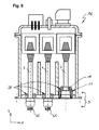
- FIG. 12 is another embodiment of the high-voltage measuring unit 1d similar to the first embodiment, similar to FIG. 1 shown. Because of this similarity, the following is only to the differences to FIG. 1 received. Identical or equivalent elements are again provided with the same reference numerals.
- this embodiment of the high-voltage measuring unit 1 d has both female and male contact parts of the plug connection 9.
- the coding achieved thereby allows for the installation of the high-voltage measuring unit 1d on the adjacent module a clear installation position.
- potential errors of confused phases 5, 7, for example, confused R and T phases can be safely ruled out in advance.
- the primary phase connection on the left (5) and in the middle (6) each have a pin-shaped contact terminal 45, while only the primary phase connection on the right (7) has a socket element 13. Both the pin-shaped contact connection 45 and the socket element 13 form parts of the detachable plug connection 9.
- the multi-part insulation body 25 comprises a cup-shaped insulation element 26 on the right-hand side of the primary phase connection 7, while the pin-shaped contact connections 45 of the left and middle primary phase connection 5, 6 have only one insulation sleeve 46 in a basic embodiment.
- Both the cup-shaped insulating element 26, and the insulating sleeve 46 form gas-tight, firm connections of the electrical insulator to the housing 3 in the region of the flange adapter portion 19. In other words, form the insulating sleeves 46 and the cup-shaped Isolation element 26 together the insulation body 25 of the high-voltage measuring unit 1a.
Landscapes
- Engineering & Computer Science (AREA)
- Power Engineering (AREA)
- Measuring Instrument Details And Bridges, And Automatic Balancing Devices (AREA)
- Transformers For Measuring Instruments (AREA)
- Connector Housings Or Holding Contact Members (AREA)
- Measuring Fluid Pressure (AREA)
Priority Applications (1)
| Application Number | Priority Date | Filing Date | Title |
|---|---|---|---|
| EP10194252A EP2346128B1 (fr) | 2010-01-18 | 2010-12-09 | Module de capteur isolé du gaz |
Applications Claiming Priority (2)
| Application Number | Priority Date | Filing Date | Title |
|---|---|---|---|
| EP10150989 | 2010-01-18 | ||
| EP10194252A EP2346128B1 (fr) | 2010-01-18 | 2010-12-09 | Module de capteur isolé du gaz |
Publications (2)
| Publication Number | Publication Date |
|---|---|
| EP2346128A1 true EP2346128A1 (fr) | 2011-07-20 |
| EP2346128B1 EP2346128B1 (fr) | 2012-11-21 |
Family
ID=42288534
Family Applications (1)
| Application Number | Title | Priority Date | Filing Date |
|---|---|---|---|
| EP10194252A Active EP2346128B1 (fr) | 2010-01-18 | 2010-12-09 | Module de capteur isolé du gaz |
Country Status (3)
| Country | Link |
|---|---|
| EP (1) | EP2346128B1 (fr) |
| KR (1) | KR101289837B1 (fr) |
| CN (1) | CN102163817B (fr) |
Cited By (3)
| Publication number | Priority date | Publication date | Assignee | Title |
|---|---|---|---|---|
| WO2015101634A1 (fr) * | 2013-12-31 | 2015-07-09 | Siemens Aktiengesellschaft | Boîtier pour transformateur de tension et transformateur de tension correspondant |
| EP3021436A1 (fr) * | 2014-11-17 | 2016-05-18 | Siemens Aktiengesellschaft | Arrangement d'enveloppe métallique apte à encapsuler un ensemble de composants électriques |
| US10276291B2 (en) * | 2017-01-12 | 2019-04-30 | Chyng Hong Electronic Co., Ltd. | Choke coil module of high power density DC-AC power inverter |
Families Citing this family (2)
| Publication number | Priority date | Publication date | Assignee | Title |
|---|---|---|---|---|
| DE102016210550B4 (de) * | 2016-06-14 | 2020-08-13 | Robert Bosch Gmbh | Sensorvorrichtung und Verfahren zur Herstellung einer Sensorvorrichtung |
| CN115527761B (zh) * | 2022-09-28 | 2024-08-16 | 信电电器集团有限公司 | 一种电压互感器生产用浇注机 |
Citations (3)
| Publication number | Priority date | Publication date | Assignee | Title |
|---|---|---|---|---|
| EP0603619A1 (fr) | 1992-12-19 | 1994-06-29 | ABBPATENT GmbH | Convertisseur de tension |
| EP0755062A1 (fr) * | 1995-07-12 | 1997-01-22 | Kommanditgesellschaft Ritz Messwandler GmbH & Co. | Transformateur de tension blindé pour appareillages de commutation avec plusieurs unités d'installation |
| EP0780941A1 (fr) * | 1995-12-22 | 1997-06-25 | ABB ADDA S.p.A. | Isolateur colonne avec un interrupteur pour haute tension et au moins un transformateur de mesure |
Family Cites Families (3)
| Publication number | Priority date | Publication date | Assignee | Title |
|---|---|---|---|---|
| JPH0935957A (ja) * | 1995-07-19 | 1997-02-07 | Hitachi Ltd | 電気機器 |
| JP2000265720A (ja) | 1999-03-16 | 2000-09-26 | Shiyoui Shinada | 車両盗難犯閉じ込め装置 |
| JP2001085254A (ja) | 1999-09-13 | 2001-03-30 | Toshiba Corp | ガス絶縁避雷器複合接地形計器用変圧器 |
-
2010
- 2010-12-09 EP EP10194252A patent/EP2346128B1/fr active Active
-
2011
- 2011-01-14 KR KR1020110003882A patent/KR101289837B1/ko active Active
- 2011-01-18 CN CN201110027789.6A patent/CN102163817B/zh active Active
Patent Citations (3)
| Publication number | Priority date | Publication date | Assignee | Title |
|---|---|---|---|---|
| EP0603619A1 (fr) | 1992-12-19 | 1994-06-29 | ABBPATENT GmbH | Convertisseur de tension |
| EP0755062A1 (fr) * | 1995-07-12 | 1997-01-22 | Kommanditgesellschaft Ritz Messwandler GmbH & Co. | Transformateur de tension blindé pour appareillages de commutation avec plusieurs unités d'installation |
| EP0780941A1 (fr) * | 1995-12-22 | 1997-06-25 | ABB ADDA S.p.A. | Isolateur colonne avec un interrupteur pour haute tension et au moins un transformateur de mesure |
Cited By (8)
| Publication number | Priority date | Publication date | Assignee | Title |
|---|---|---|---|---|
| WO2015101634A1 (fr) * | 2013-12-31 | 2015-07-09 | Siemens Aktiengesellschaft | Boîtier pour transformateur de tension et transformateur de tension correspondant |
| US20160300656A1 (en) * | 2013-12-31 | 2016-10-13 | Siemens Aktiengesellschaft | Enclosure for voltage transformer and corresponding voltage transformer |
| JP2017501593A (ja) * | 2013-12-31 | 2017-01-12 | シーメンス アクティエンゲゼルシャフト | 変圧器のための筐体および対応した変圧器 |
| RU2667084C2 (ru) * | 2013-12-31 | 2018-09-14 | Сименс Акциенгезелльшафт | Ограждение для трансформатора напряжения и соответствующий трансформатор напряжения |
| US10304609B2 (en) * | 2013-12-31 | 2019-05-28 | Siemens Aktiengesellschaft | Enclosure for voltage transformer and corresponding voltage transformer |
| EP3021436A1 (fr) * | 2014-11-17 | 2016-05-18 | Siemens Aktiengesellschaft | Arrangement d'enveloppe métallique apte à encapsuler un ensemble de composants électriques |
| WO2016078907A1 (fr) * | 2014-11-17 | 2016-05-26 | Siemens Aktiengesellschaft | Arrangement d'enveloppe metallique apte a encapsuler un ensemble de composants electriques |
| US10276291B2 (en) * | 2017-01-12 | 2019-04-30 | Chyng Hong Electronic Co., Ltd. | Choke coil module of high power density DC-AC power inverter |
Also Published As
| Publication number | Publication date |
|---|---|
| CN102163817A (zh) | 2011-08-24 |
| EP2346128B1 (fr) | 2012-11-21 |
| KR101289837B1 (ko) | 2013-07-26 |
| KR20110084834A (ko) | 2011-07-26 |
| CN102163817B (zh) | 2014-04-02 |
Similar Documents
| Publication | Publication Date | Title |
|---|---|---|
| EP2346128B1 (fr) | Module de capteur isolé du gaz | |
| EP2873126B1 (fr) | Installation de commutation à isolation gazeuse | |
| EP2346053B1 (fr) | Unité de mesure haute tension isolée du gaz | |
| WO2010133500A1 (fr) | Connexions enfichables d'alimentation primaire de deux modules d'un appareillage de commutation haute tension à isolation gazeuse | |
| DE102016216949A1 (de) | Transformator für die Hochspannungsgleichstromübertragung | |
| DE10317735B3 (de) | Erdungsschalter mit einem bewegbaren Kontaktstück | |
| EP1547218B1 (fr) | Couplage des barres pour une installation de distribution etanche au gaz | |
| DE10032656B4 (de) | Freiluft-Hochspannungs-Durchführung und Hochspannungs-Schaltgerät mit einer solchen Durchführung | |
| EP2254209B1 (fr) | Connexions de sortie primaires enfichables de deux modules d'une installation de commutation haute tension à isolation gazeuse | |
| EP0796502B1 (fr) | Appareillage de commutation mis sous boitier metallique, comportant un interrupteur a vide | |
| EP2146411A2 (fr) | Couplage de barres collectrices pour une installation de commutation électrique | |
| EP0678953B1 (fr) | Terminaison de câble pour un appareillage de commutation blindé métallique à haute tension et à isolement gazeux | |
| DE3904439A1 (de) | Metallgekapselter druckgas-leistungsschalter mit anschlussvorrichtungen der unterbrechereinheit | |
| EP0436256B1 (fr) | Installation de commutation avec un récipient blindé à isolation gazeuse et interrupteur rotatif multiposition | |
| DE2233217A1 (de) | Trommelbare kabellaenge eines gasisolierten hochspannungskabels | |
| DE10325682A1 (de) | Gasisoliertes Sammelschienenbauteil mit Freiluftdurchführung | |
| EP2905854B1 (fr) | Dispositif de mesure de tension capacitif et un agencement de barre collectrice d'une installation de commutation et installation de commutation | |
| DE19850694B4 (de) | Gasisolierte Schaltanlage | |
| DE19959450B4 (de) | Elektrische Steckverbindung, welche sich während der Montage der isoliergasbefüllten Schaltanlagenkomponenten selbsttätig mit Isoliergas befüllt | |
| EP2283492B1 (fr) | Ensemble comprenant une traversée de mesure étanche aux gaz | |
| EP0999623B1 (fr) | Installation de commutation à gaz isolant | |
| EP0667662B1 (fr) | Installation de commutation avec canal de connexion | |
| WO2016156327A1 (fr) | Ensemble boîtier blindé | |
| DE19937072A1 (de) | Feststoffisoliert ummanteltes Verbindungselement | |
| DE102010004971A1 (de) | Vorrichtung für eine Schaltanlage |
Legal Events
| Date | Code | Title | Description |
|---|---|---|---|
| PUAI | Public reference made under article 153(3) epc to a published international application that has entered the european phase |
Free format text: ORIGINAL CODE: 0009012 |
|
| AK | Designated contracting states |
Kind code of ref document: A1 Designated state(s): AL AT BE BG CH CY CZ DE DK EE ES FI FR GB GR HR HU IE IS IT LI LT LU LV MC MK MT NL NO PL PT RO RS SE SI SK SM TR |
|
| AX | Request for extension of the european patent |
Extension state: BA ME |
|
| 17P | Request for examination filed |
Effective date: 20120119 |
|
| RIC1 | Information provided on ipc code assigned before grant |
Ipc: H02B 13/035 20060101AFI20120418BHEP |
|
| GRAP | Despatch of communication of intention to grant a patent |
Free format text: ORIGINAL CODE: EPIDOSNIGR1 |
|
| GRAS | Grant fee paid |
Free format text: ORIGINAL CODE: EPIDOSNIGR3 |
|
| GRAA | (expected) grant |
Free format text: ORIGINAL CODE: 0009210 |
|
| AK | Designated contracting states |
Kind code of ref document: B1 Designated state(s): AL AT BE BG CH CY CZ DE DK EE ES FI FR GB GR HR HU IE IS IT LI LT LU LV MC MK MT NL NO PL PT RO RS SE SI SK SM TR |
|
| REG | Reference to a national code |
Ref country code: GB Ref legal event code: FG4D Free format text: NOT ENGLISH |
|
| REG | Reference to a national code |
Ref country code: CH Ref legal event code: EP |
|
| REG | Reference to a national code |
Ref country code: CH Ref legal event code: NV Representative=s name: ABB SCHWEIZ AG INTELLECTUAL PROPERTY (CH-LC/IP, CH |
|
| REG | Reference to a national code |
Ref country code: AT Ref legal event code: REF Ref document number: 585498 Country of ref document: AT Kind code of ref document: T Effective date: 20121215 |
|
| REG | Reference to a national code |
Ref country code: IE Ref legal event code: FG4D Free format text: LANGUAGE OF EP DOCUMENT: GERMAN |
|
| REG | Reference to a national code |
Ref country code: DE Ref legal event code: R096 Ref document number: 502010001680 Country of ref document: DE Effective date: 20130117 |
|
| REG | Reference to a national code |
Ref country code: NL Ref legal event code: VDEP Effective date: 20121121 |
|
| REG | Reference to a national code |
Ref country code: LT Ref legal event code: MG4D |
|
| PG25 | Lapsed in a contracting state [announced via postgrant information from national office to epo] |
Ref country code: HR Free format text: LAPSE BECAUSE OF FAILURE TO SUBMIT A TRANSLATION OF THE DESCRIPTION OR TO PAY THE FEE WITHIN THE PRESCRIBED TIME-LIMIT Effective date: 20121121 Ref country code: LT Free format text: LAPSE BECAUSE OF FAILURE TO SUBMIT A TRANSLATION OF THE DESCRIPTION OR TO PAY THE FEE WITHIN THE PRESCRIBED TIME-LIMIT Effective date: 20121121 Ref country code: SE Free format text: LAPSE BECAUSE OF FAILURE TO SUBMIT A TRANSLATION OF THE DESCRIPTION OR TO PAY THE FEE WITHIN THE PRESCRIBED TIME-LIMIT Effective date: 20121121 Ref country code: FI Free format text: LAPSE BECAUSE OF FAILURE TO SUBMIT A TRANSLATION OF THE DESCRIPTION OR TO PAY THE FEE WITHIN THE PRESCRIBED TIME-LIMIT Effective date: 20121121 Ref country code: ES Free format text: LAPSE BECAUSE OF FAILURE TO SUBMIT A TRANSLATION OF THE DESCRIPTION OR TO PAY THE FEE WITHIN THE PRESCRIBED TIME-LIMIT Effective date: 20130304 Ref country code: NO Free format text: LAPSE BECAUSE OF FAILURE TO SUBMIT A TRANSLATION OF THE DESCRIPTION OR TO PAY THE FEE WITHIN THE PRESCRIBED TIME-LIMIT Effective date: 20130221 |
|
| PG25 | Lapsed in a contracting state [announced via postgrant information from national office to epo] |
Ref country code: PT Free format text: LAPSE BECAUSE OF FAILURE TO SUBMIT A TRANSLATION OF THE DESCRIPTION OR TO PAY THE FEE WITHIN THE PRESCRIBED TIME-LIMIT Effective date: 20130321 Ref country code: LV Free format text: LAPSE BECAUSE OF FAILURE TO SUBMIT A TRANSLATION OF THE DESCRIPTION OR TO PAY THE FEE WITHIN THE PRESCRIBED TIME-LIMIT Effective date: 20121121 Ref country code: SI Free format text: LAPSE BECAUSE OF FAILURE TO SUBMIT A TRANSLATION OF THE DESCRIPTION OR TO PAY THE FEE WITHIN THE PRESCRIBED TIME-LIMIT Effective date: 20121121 Ref country code: GR Free format text: LAPSE BECAUSE OF FAILURE TO SUBMIT A TRANSLATION OF THE DESCRIPTION OR TO PAY THE FEE WITHIN THE PRESCRIBED TIME-LIMIT Effective date: 20130222 Ref country code: PL Free format text: LAPSE BECAUSE OF FAILURE TO SUBMIT A TRANSLATION OF THE DESCRIPTION OR TO PAY THE FEE WITHIN THE PRESCRIBED TIME-LIMIT Effective date: 20121121 |
|
| BERE | Be: lapsed |
Owner name: ABB TECHNOLOGY A.G. Effective date: 20121231 |
|
| PG25 | Lapsed in a contracting state [announced via postgrant information from national office to epo] |
Ref country code: DK Free format text: LAPSE BECAUSE OF FAILURE TO SUBMIT A TRANSLATION OF THE DESCRIPTION OR TO PAY THE FEE WITHIN THE PRESCRIBED TIME-LIMIT Effective date: 20121121 Ref country code: EE Free format text: LAPSE BECAUSE OF FAILURE TO SUBMIT A TRANSLATION OF THE DESCRIPTION OR TO PAY THE FEE WITHIN THE PRESCRIBED TIME-LIMIT Effective date: 20121121 Ref country code: RS Free format text: LAPSE BECAUSE OF FAILURE TO SUBMIT A TRANSLATION OF THE DESCRIPTION OR TO PAY THE FEE WITHIN THE PRESCRIBED TIME-LIMIT Effective date: 20121121 Ref country code: MC Free format text: LAPSE BECAUSE OF NON-PAYMENT OF DUE FEES Effective date: 20121231 Ref country code: BG Free format text: LAPSE BECAUSE OF FAILURE TO SUBMIT A TRANSLATION OF THE DESCRIPTION OR TO PAY THE FEE WITHIN THE PRESCRIBED TIME-LIMIT Effective date: 20130221 Ref country code: SK Free format text: LAPSE BECAUSE OF FAILURE TO SUBMIT A TRANSLATION OF THE DESCRIPTION OR TO PAY THE FEE WITHIN THE PRESCRIBED TIME-LIMIT Effective date: 20121121 Ref country code: CZ Free format text: LAPSE BECAUSE OF FAILURE TO SUBMIT A TRANSLATION OF THE DESCRIPTION OR TO PAY THE FEE WITHIN THE PRESCRIBED TIME-LIMIT Effective date: 20121121 |
|
| PG25 | Lapsed in a contracting state [announced via postgrant information from national office to epo] |
Ref country code: NL Free format text: LAPSE BECAUSE OF FAILURE TO SUBMIT A TRANSLATION OF THE DESCRIPTION OR TO PAY THE FEE WITHIN THE PRESCRIBED TIME-LIMIT Effective date: 20121121 Ref country code: RO Free format text: LAPSE BECAUSE OF FAILURE TO SUBMIT A TRANSLATION OF THE DESCRIPTION OR TO PAY THE FEE WITHIN THE PRESCRIBED TIME-LIMIT Effective date: 20121121 Ref country code: IT Free format text: LAPSE BECAUSE OF FAILURE TO SUBMIT A TRANSLATION OF THE DESCRIPTION OR TO PAY THE FEE WITHIN THE PRESCRIBED TIME-LIMIT Effective date: 20121121 |
|
| REG | Reference to a national code |
Ref country code: IE Ref legal event code: MM4A |
|
| PLBE | No opposition filed within time limit |
Free format text: ORIGINAL CODE: 0009261 |
|
| STAA | Information on the status of an ep patent application or granted ep patent |
Free format text: STATUS: NO OPPOSITION FILED WITHIN TIME LIMIT |
|
| PG25 | Lapsed in a contracting state [announced via postgrant information from national office to epo] |
Ref country code: BE Free format text: LAPSE BECAUSE OF NON-PAYMENT OF DUE FEES Effective date: 20121231 |
|
| 26N | No opposition filed |
Effective date: 20130822 |
|
| PG25 | Lapsed in a contracting state [announced via postgrant information from national office to epo] |
Ref country code: IE Free format text: LAPSE BECAUSE OF NON-PAYMENT OF DUE FEES Effective date: 20121209 |
|
| PG25 | Lapsed in a contracting state [announced via postgrant information from national office to epo] |
Ref country code: MT Free format text: LAPSE BECAUSE OF FAILURE TO SUBMIT A TRANSLATION OF THE DESCRIPTION OR TO PAY THE FEE WITHIN THE PRESCRIBED TIME-LIMIT Effective date: 20121121 Ref country code: AL Free format text: LAPSE BECAUSE OF FAILURE TO SUBMIT A TRANSLATION OF THE DESCRIPTION OR TO PAY THE FEE WITHIN THE PRESCRIBED TIME-LIMIT Effective date: 20121121 |
|
| REG | Reference to a national code |
Ref country code: DE Ref legal event code: R097 Ref document number: 502010001680 Country of ref document: DE Effective date: 20130822 |
|
| PG25 | Lapsed in a contracting state [announced via postgrant information from national office to epo] |
Ref country code: TR Free format text: LAPSE BECAUSE OF FAILURE TO SUBMIT A TRANSLATION OF THE DESCRIPTION OR TO PAY THE FEE WITHIN THE PRESCRIBED TIME-LIMIT Effective date: 20121121 |
|
| PG25 | Lapsed in a contracting state [announced via postgrant information from national office to epo] |
Ref country code: LU Free format text: LAPSE BECAUSE OF NON-PAYMENT OF DUE FEES Effective date: 20121209 Ref country code: CY Free format text: LAPSE BECAUSE OF FAILURE TO SUBMIT A TRANSLATION OF THE DESCRIPTION OR TO PAY THE FEE WITHIN THE PRESCRIBED TIME-LIMIT Effective date: 20121121 Ref country code: SM Free format text: LAPSE BECAUSE OF FAILURE TO SUBMIT A TRANSLATION OF THE DESCRIPTION OR TO PAY THE FEE WITHIN THE PRESCRIBED TIME-LIMIT Effective date: 20121121 |
|
| PG25 | Lapsed in a contracting state [announced via postgrant information from national office to epo] |
Ref country code: HU Free format text: LAPSE BECAUSE OF FAILURE TO SUBMIT A TRANSLATION OF THE DESCRIPTION OR TO PAY THE FEE WITHIN THE PRESCRIBED TIME-LIMIT Effective date: 20101209 |
|
| REG | Reference to a national code |
Ref country code: DE Ref legal event code: R082 Ref document number: 502010001680 Country of ref document: DE |
|
| PG25 | Lapsed in a contracting state [announced via postgrant information from national office to epo] |
Ref country code: MK Free format text: LAPSE BECAUSE OF FAILURE TO SUBMIT A TRANSLATION OF THE DESCRIPTION OR TO PAY THE FEE WITHIN THE PRESCRIBED TIME-LIMIT Effective date: 20121121 |
|
| GBPC | Gb: european patent ceased through non-payment of renewal fee |
Effective date: 20141209 |
|
| PG25 | Lapsed in a contracting state [announced via postgrant information from national office to epo] |
Ref country code: GB Free format text: LAPSE BECAUSE OF NON-PAYMENT OF DUE FEES Effective date: 20141209 |
|
| REG | Reference to a national code |
Ref country code: FR Ref legal event code: PLFP Year of fee payment: 6 |
|
| PG25 | Lapsed in a contracting state [announced via postgrant information from national office to epo] |
Ref country code: IS Free format text: LAPSE BECAUSE OF FAILURE TO SUBMIT A TRANSLATION OF THE DESCRIPTION OR TO PAY THE FEE WITHIN THE PRESCRIBED TIME-LIMIT Effective date: 20121121 |
|
| REG | Reference to a national code |
Ref country code: DE Ref legal event code: R081 Ref document number: 502010001680 Country of ref document: DE Owner name: HITACHI ENERGY SWITZERLAND AG, CH Free format text: FORMER OWNER: ABB TECHNOLOGY AG, ZUERICH, CH Ref country code: DE Ref legal event code: R081 Ref document number: 502010001680 Country of ref document: DE Owner name: ABB POWER GRIDS SWITZERLAND AG, CH Free format text: FORMER OWNER: ABB TECHNOLOGY AG, ZUERICH, CH Ref country code: DE Ref legal event code: R081 Ref document number: 502010001680 Country of ref document: DE Owner name: ABB SCHWEIZ AG, CH Free format text: FORMER OWNER: ABB TECHNOLOGY AG, ZUERICH, CH |
|
| REG | Reference to a national code |
Ref country code: FR Ref legal event code: PLFP Year of fee payment: 7 |
|
| REG | Reference to a national code |
Ref country code: AT Ref legal event code: MM01 Ref document number: 585498 Country of ref document: AT Kind code of ref document: T Effective date: 20151209 |
|
| PG25 | Lapsed in a contracting state [announced via postgrant information from national office to epo] |
Ref country code: AT Free format text: LAPSE BECAUSE OF NON-PAYMENT OF DUE FEES Effective date: 20151209 |
|
| REG | Reference to a national code |
Ref country code: FR Ref legal event code: PLFP Year of fee payment: 8 |
|
| REG | Reference to a national code |
Ref country code: CH Ref legal event code: PFUS Owner name: ABB SCHWEIZ AG, CH Free format text: FORMER OWNER: ABB TECHNOLOGY AG, CH |
|
| REG | Reference to a national code |
Ref country code: FR Ref legal event code: TP Owner name: ABB SCHWEIZ AG, CH Effective date: 20180912 |
|
| REG | Reference to a national code |
Ref country code: CH Ref legal event code: PUE Owner name: ABB POWER GRIDS SWITZERLAND AG, CH Free format text: FORMER OWNER: ABB SCHWEIZ AG, CH |
|
| REG | Reference to a national code |
Ref country code: DE Ref legal event code: R081 Ref document number: 502010001680 Country of ref document: DE Owner name: HITACHI ENERGY SWITZERLAND AG, CH Free format text: FORMER OWNER: ABB SCHWEIZ AG, BADEN, CH Ref country code: DE Ref legal event code: R082 Ref document number: 502010001680 Country of ref document: DE Representative=s name: DENNEMEYER & ASSOCIATES RECHTSANWALTSGESELLSCH, DE Ref country code: DE Ref legal event code: R081 Ref document number: 502010001680 Country of ref document: DE Owner name: HITACHI ENERGY LTD, CH Free format text: FORMER OWNER: ABB SCHWEIZ AG, BADEN, CH Ref country code: DE Ref legal event code: R081 Ref document number: 502010001680 Country of ref document: DE Owner name: ABB POWER GRIDS SWITZERLAND AG, CH Free format text: FORMER OWNER: ABB SCHWEIZ AG, BADEN, CH Ref country code: DE Ref legal event code: R082 Ref document number: 502010001680 Country of ref document: DE Representative=s name: DENNEMEYER & ASSOCIATES S.A., DE |
|
| REG | Reference to a national code |
Ref country code: DE Ref legal event code: R081 Ref document number: 502010001680 Country of ref document: DE Owner name: HITACHI ENERGY SWITZERLAND AG, CH Free format text: FORMER OWNER: ABB POWER GRIDS SWITZERLAND AG, BADEN, CH Ref country code: DE Ref legal event code: R081 Ref document number: 502010001680 Country of ref document: DE Owner name: HITACHI ENERGY LTD, CH Free format text: FORMER OWNER: ABB POWER GRIDS SWITZERLAND AG, BADEN, CH |
|
| P01 | Opt-out of the competence of the unified patent court (upc) registered |
Effective date: 20230527 |
|
| REG | Reference to a national code |
Ref country code: DE Ref legal event code: R082 Ref document number: 502010001680 Country of ref document: DE Representative=s name: DENNEMEYER & ASSOCIATES RECHTSANWALTSGESELLSCH, DE Ref country code: DE Ref legal event code: R082 Ref document number: 502010001680 Country of ref document: DE Representative=s name: DENNEMEYER & ASSOCIATES S.A., DE Ref country code: DE Ref legal event code: R081 Ref document number: 502010001680 Country of ref document: DE Owner name: HITACHI ENERGY LTD, CH Free format text: FORMER OWNER: HITACHI ENERGY SWITZERLAND AG, BADEN, CH |
|
| REG | Reference to a national code |
Ref country code: DE Ref legal event code: R082 Ref document number: 502010001680 Country of ref document: DE Representative=s name: DENNEMEYER & ASSOCIATES RECHTSANWALTSGESELLSCH, DE |
|
| REG | Reference to a national code |
Ref country code: CH Ref legal event code: U11 Free format text: ST27 STATUS EVENT CODE: U-0-0-U10-U11 (AS PROVIDED BY THE NATIONAL OFFICE) Effective date: 20260101 |
|
| PGFP | Annual fee paid to national office [announced via postgrant information from national office to epo] |
Ref country code: DE Payment date: 20251211 Year of fee payment: 16 |
|
| PGFP | Annual fee paid to national office [announced via postgrant information from national office to epo] |
Ref country code: FR Payment date: 20251222 Year of fee payment: 16 |
|
| PGFP | Annual fee paid to national office [announced via postgrant information from national office to epo] |
Ref country code: CH Payment date: 20260101 Year of fee payment: 16 |