EP0781855A1 - Installation de traitement thermique - Google Patents
Installation de traitement thermique Download PDFInfo
- Publication number
- EP0781855A1 EP0781855A1 EP96309411A EP96309411A EP0781855A1 EP 0781855 A1 EP0781855 A1 EP 0781855A1 EP 96309411 A EP96309411 A EP 96309411A EP 96309411 A EP96309411 A EP 96309411A EP 0781855 A1 EP0781855 A1 EP 0781855A1
- Authority
- EP
- European Patent Office
- Prior art keywords
- heat treatment
- opening
- treatment furnace
- seal
- pusher
- Prior art date
- Legal status (The legal status is an assumption and is not a legal conclusion. Google has not performed a legal analysis and makes no representation as to the accuracy of the status listed.)
- Granted
Links
- 238000010438 heat treatment Methods 0.000 title claims abstract description 49
- 238000001816 cooling Methods 0.000 claims abstract description 12
- 238000012856 packing Methods 0.000 claims abstract description 10
- 239000004215 Carbon black (E152) Substances 0.000 claims abstract description 4
- 229930195733 hydrocarbon Natural products 0.000 claims abstract description 4
- 150000002430 hydrocarbons Chemical class 0.000 claims abstract description 4
- 238000007254 oxidation reaction Methods 0.000 claims abstract description 3
- 238000003780 insertion Methods 0.000 abstract description 3
- 230000037431 insertion Effects 0.000 abstract description 3
- 239000007789 gas Substances 0.000 description 9
- 238000000034 method Methods 0.000 description 3
- 238000006243 chemical reaction Methods 0.000 description 2
- 230000007547 defect Effects 0.000 description 2
- 229910052751 metal Inorganic materials 0.000 description 2
- 239000002184 metal Substances 0.000 description 2
- 150000002739 metals Chemical class 0.000 description 2
- OKTJSMMVPCPJKN-UHFFFAOYSA-N Carbon Chemical compound [C] OKTJSMMVPCPJKN-UHFFFAOYSA-N 0.000 description 1
- 229910052799 carbon Inorganic materials 0.000 description 1
- 239000012159 carrier gas Substances 0.000 description 1
- 230000003247 decreasing effect Effects 0.000 description 1
- 239000000463 material Substances 0.000 description 1
- 230000001590 oxidative effect Effects 0.000 description 1
- 238000010791 quenching Methods 0.000 description 1
- 230000000171 quenching effect Effects 0.000 description 1
Images



Classifications
-
- C—CHEMISTRY; METALLURGY
- C21—METALLURGY OF IRON
- C21D—MODIFYING THE PHYSICAL STRUCTURE OF FERROUS METALS; GENERAL DEVICES FOR HEAT TREATMENT OF FERROUS OR NON-FERROUS METALS OR ALLOYS; MAKING METAL MALLEABLE, e.g. BY DECARBURISATION OR TEMPERING
- C21D1/00—General methods or devices for heat treatment, e.g. annealing, hardening, quenching or tempering
-
- F—MECHANICAL ENGINEERING; LIGHTING; HEATING; WEAPONS; BLASTING
- F27—FURNACES; KILNS; OVENS; RETORTS
- F27D—DETAILS OR ACCESSORIES OF FURNACES, KILNS, OVENS OR RETORTS, IN SO FAR AS THEY ARE OF KINDS OCCURRING IN MORE THAN ONE KIND OF FURNACE
- F27D99/00—Subject matter not provided for in other groups of this subclass
- F27D99/0073—Seals
-
- C—CHEMISTRY; METALLURGY
- C21—METALLURGY OF IRON
- C21D—MODIFYING THE PHYSICAL STRUCTURE OF FERROUS METALS; GENERAL DEVICES FOR HEAT TREATMENT OF FERROUS OR NON-FERROUS METALS OR ALLOYS; MAKING METAL MALLEABLE, e.g. BY DECARBURISATION OR TEMPERING
- C21D1/00—General methods or devices for heat treatment, e.g. annealing, hardening, quenching or tempering
- C21D1/74—Methods of treatment in inert gas, controlled atmosphere, vacuum or pulverulent material
-
- C—CHEMISTRY; METALLURGY
- C21—METALLURGY OF IRON
- C21D—MODIFYING THE PHYSICAL STRUCTURE OF FERROUS METALS; GENERAL DEVICES FOR HEAT TREATMENT OF FERROUS OR NON-FERROUS METALS OR ALLOYS; MAKING METAL MALLEABLE, e.g. BY DECARBURISATION OR TEMPERING
- C21D9/00—Heat treatment, e.g. annealing, hardening, quenching or tempering, adapted for particular articles; Furnaces therefor
- C21D9/0006—Details, accessories not peculiar to any of the following furnaces
-
- F—MECHANICAL ENGINEERING; LIGHTING; HEATING; WEAPONS; BLASTING
- F27—FURNACES; KILNS; OVENS; RETORTS
- F27B—FURNACES, KILNS, OVENS OR RETORTS IN GENERAL; OPEN SINTERING OR LIKE APPARATUS
- F27B9/00—Furnaces through which the charge is moved mechanically, e.g. of tunnel type; Similar furnaces in which the charge moves by gravity
- F27B9/04—Furnaces through which the charge is moved mechanically, e.g. of tunnel type; Similar furnaces in which the charge moves by gravity adapted for treating the charge in vacuum or special atmosphere
- F27B9/045—Furnaces with controlled atmosphere
-
- F—MECHANICAL ENGINEERING; LIGHTING; HEATING; WEAPONS; BLASTING
- F27—FURNACES; KILNS; OVENS; RETORTS
- F27B—FURNACES, KILNS, OVENS OR RETORTS IN GENERAL; OPEN SINTERING OR LIKE APPARATUS
- F27B9/00—Furnaces through which the charge is moved mechanically, e.g. of tunnel type; Similar furnaces in which the charge moves by gravity
- F27B9/14—Furnaces through which the charge is moved mechanically, e.g. of tunnel type; Similar furnaces in which the charge moves by gravity characterised by the path of the charge during treatment; characterised by the means by which the charge is moved during treatment
- F27B9/20—Furnaces through which the charge is moved mechanically, e.g. of tunnel type; Similar furnaces in which the charge moves by gravity characterised by the path of the charge during treatment; characterised by the means by which the charge is moved during treatment the charge moving in a substantially straight path
- F27B9/22—Furnaces through which the charge is moved mechanically, e.g. of tunnel type; Similar furnaces in which the charge moves by gravity characterised by the path of the charge during treatment; characterised by the means by which the charge is moved during treatment the charge moving in a substantially straight path on rails, e.g. under the action of scrapers or pushers
-
- F—MECHANICAL ENGINEERING; LIGHTING; HEATING; WEAPONS; BLASTING
- F27—FURNACES; KILNS; OVENS; RETORTS
- F27D—DETAILS OR ACCESSORIES OF FURNACES, KILNS, OVENS OR RETORTS, IN SO FAR AS THEY ARE OF KINDS OCCURRING IN MORE THAN ONE KIND OF FURNACE
- F27D1/00—Casings; Linings; Walls; Roofs
- F27D1/18—Door frames; Doors, lids or removable covers
- F27D1/1858—Doors
-
- F—MECHANICAL ENGINEERING; LIGHTING; HEATING; WEAPONS; BLASTING
- F27—FURNACES; KILNS; OVENS; RETORTS
- F27D—DETAILS OR ACCESSORIES OF FURNACES, KILNS, OVENS OR RETORTS, IN SO FAR AS THEY ARE OF KINDS OCCURRING IN MORE THAN ONE KIND OF FURNACE
- F27D3/00—Charging; Discharging; Manipulation of charge
- F27D3/04—Ram or pusher apparatus
Definitions
- This invention relates to a heat treatment apparatus, and more particularly relates to a heat treatment apparatus having a heat treatment furnace into which a hydrocarbon gas and an oxidization gas are introduced in order to heat treating metals.
- Fig. 7 shows a conventional batch furnace.
- a reference numeral 1 denotes a heating room
- 2 denotes a cooling room
- 3 an entrance door for said heating room 1
- 3a an opening and closing port formed on said entrance door 3
- 4 an intermediate door
- 4a an outlet formed on said intermediate door 4
- 5 an outlet door for said cooling room 2
- 6 a cooling oil tank
- 7 an excess air exhausting device
- 8 a curtain flame to be ignited when the outlet door 5 is opened
- Fig. 8 shows a conventional continuous furnace and parts of the furnace which are similar to the corresponding parts of the furnace shown in Fig. 7 have been given corresponding reference numerals and need not be further described.
- a reference numeral 15 denotes a work receiving room, 16 a door for the work receiving room 15, 17 a CO 2 supply pipe, 18 is valve provided in said CO 2 supply pipe 17, and 20 a gas material supply pipe.
- a converted gas obtained from the conversion furnace is used as a carrier gas.
- a hydrocarbon gas and an oxidizing gas are introduced directly into the furnace to carry out the metamorphism and the cementation in the furnace.
- a cementation method that the carbon potential in the furnace atmosphere is increased and decreased repeatedly to reduce the treatment time is described in Japanese Patent Laid Open Nos. 128577/1980 and 49621/1994, Japanese Patent Publication Nos. 38870/ 1989, 51904/1994 and 21866/1987, for example.
- Fig. 9 shows a heat treatment furnace in said Japanese Patent Publication No. 21866/1987, wherein the entrance door 3 is opened at first, and then a work is inserted into a vestibule 22 by a pusher 21.
- the door 24 is closed and after the heating treatment is completed a door 26 is opened and the work is moved by a pusher 25 into the cooling room 2. Then, the door 26 is closed and the temperature in the cooling room 2 is reduced, and at the same time the intermediate door 4 is opened and the work is moved by a pusher 27 into the cooling oil tank 6. Then, the intermediate door 4 is closed to carry out the quenching. Next, the outlet door 5 is opened, and the work is discharged to the outside, and then the outlet door 5 is closed.
- the conventional heat treatment apparatus for metals using an endothermic gas has such a defect that it is difficult to form a hermetical seal of the apparatus.
- An object of the present invention is to obviate the above defect of the conventional heat treatment apparatus.
- a heat treatment apparatus comprises a valve having an outlet opening and an inlet opening through which a pusher for pushing a work to be heat treated in said heat treatment furnace is movable, said outlet opening of the valve being hermetically connected to a pusher inserting port formed on a wall of said heat treatment furnace, and a seal box hermetically connected to said inlet opening of the valve, said pusher being movable hermetically through said seal box.
- said valve is closed when said pusher is withdrawn therefrom, and is opened when said pusher is inserted thereinto.
- the heat treatment apparatus further comprises an elevator door for opening and closing an opening of said heat treatment furnace, a guide pin projected from said elevator door, and a jam having an upper hook surface for receiving said guide pin thereon, said jam being pivotally supported so that when said elevator door is lowered, said elevator door is moved by said jam toward a seal surface of an opening of said heat treatment furnace.
- the heat treatment apparatus further comprises an elevator door for opening and closing an opening of said heat treatment furnace, a guide pin projected from said elevator door, and a guide groove for guiding said pin in the vertical direction, wherein a lower end portion of said groove is curved toward a seal surface of an opening of said heat treatment furnace.
- a seal packing is provided on a seal surface of an opening of said heat treatment furnace, and a cooling pipe is provided near said seal packing.
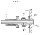
- Fig. 1 is a sectional side view of a hermetical seal of a pusher portion of a heat treatment apparatus in accordance with the present invention.
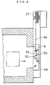
- Fig. 2 is a sectional side view of an intermediate door portion of the heat treatment apparatus.
- Fig. 3 is a front view of the intermediate door portion.
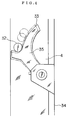
- Fig. 4 is an enlarged side view of a guide means for the door.
- Fig. 5 is an enlarged side view of a guide means for an entrance door of the heat treatment apparatus.
- Fig. 6 is a front view of a seal portion of an opening of the heat treatment apparatus.
- Fig. 7 is a sectional side view of a conventional batch furnace.
- Fig. 8 is a sectional side view of a conventional continuous furnace.
- Fig. 9 is a sectional side view of the other conventional continuous furnace.
- Fig. 1 shows an improved hermetical seal for one 27 of the pushers 23, 25 and 27 shown in Fig. 9.
- a ball valve 30 and a seal box 31 are arranged in this order adjacent to the outer surface of a furnace wall 28 of the room 1 or 2 corresponding to a pusher insertion port 29 formed on the furnace wall 28.
- the pusher 27, for example, can be moved passing through said seal box 31, ball valve 30 and pusher insertion port 29 and inserted into the cooling room 2, for example.
- a work to be heat treated is inserted into the room 2 by the pusher 27 in the state that the ball valve 30 is opened, then the pusher 27 is withdrawn from the room 2 through the ball valve 30 into the seal box 31, and then the ball valve 30 is closed.
- the work can be inserted into the room 2 without breaking the hermetical seal of the room 2.
- Figs. 2 to 4 show one of the doors 4, 24 and 26, for example, the intermediate door 4 in the heat treatment apparatus of the present invention.
- guide pins 32 are projected in the horizontal direction from both sides of the door 4, planar jams 35 each having an upper hook surface 33 for receiving said guide pin 32 and a lower portion pivotally supported by a frame 34 are provided, and the intermediate door 4 is moved up and down through chains 36 by an elevator device 37, so that when the intermediate door 4 is lowered in order to close the outlet of the room 2, the guide pins 32 of the intermediate door 4 are engaged with the upper portions of the hook surfaces 33 of the jams 35 and guided along the hook surfaces 33 leftwords in Fig. 4.
- the jams 35 are rotated in the counter-clockwise direction as shown by a double dot -and- dush line in Fig. 4, so that the surface of the intermediate door 4 is pressed to the seal surface of the room 2.
- the intermediate door 4 does not contact with the seal surface of the room 2 in the course of lowering and lifting, and only when the intermediate door 4 is reached to the lowest position, the intermediate door 4 is in contact with the seal surface of the room 2, so that the seal surface is never damaged when the door is moved up and down.
- Fig. 5 shows one of guide grooves 40 formed on a frame 38 for the entrance door 3 or the outlet door 5.
- guide pins 39 are projected in the horizontal direction from both sides of the door, and guided by guide grooves 40, respectively.
- Each of said grooves 40 is curved at the lower portion thereof toward the seal surface of the room 1 or the room 2.
- the door does not contact with the seal surface of the heating room 1 or cooling room 2 in the course of lowering and lifting, and only when the door is reached to the lowest position, the door is brought into contact with the seal surface, so that the seal surface is never damaged when the door is moved up and down.
- Fig. 6 shows seal packing 41 arranged on the seal surface of the heating room 1.
- the seal packing 41 are surrounded with an air pipe 42 into which a cooling air is introduce d so as to cool the seal packing 41.
- the seal packing can be prevented from being deteriorated.
Landscapes
- Engineering & Computer Science (AREA)
- Chemical & Material Sciences (AREA)
- Mechanical Engineering (AREA)
- General Engineering & Computer Science (AREA)
- Crystallography & Structural Chemistry (AREA)
- Thermal Sciences (AREA)
- Physics & Mathematics (AREA)
- Materials Engineering (AREA)
- Metallurgy (AREA)
- Organic Chemistry (AREA)
- Furnace Details (AREA)
- Tunnel Furnaces (AREA)
- Heat Treatments In General, Especially Conveying And Cooling (AREA)
- Solid-Phase Diffusion Into Metallic Material Surfaces (AREA)
Priority Applications (1)
| Application Number | Priority Date | Filing Date | Title |
|---|---|---|---|
| EP00200816A EP1028168B1 (fr) | 1995-12-28 | 1996-12-23 | Installation de traitement thermique |
Applications Claiming Priority (3)
| Application Number | Priority Date | Filing Date | Title |
|---|---|---|---|
| JP35234395 | 1995-12-28 | ||
| JP35234395A JP3378974B2 (ja) | 1995-12-28 | 1995-12-28 | 金属の熱処理装置 |
| JP352343/95 | 1995-12-28 |
Related Child Applications (1)
| Application Number | Title | Priority Date | Filing Date |
|---|---|---|---|
| EP00200816A Division EP1028168B1 (fr) | 1995-12-28 | 1996-12-23 | Installation de traitement thermique |
Publications (2)
| Publication Number | Publication Date |
|---|---|
| EP0781855A1 true EP0781855A1 (fr) | 1997-07-02 |
| EP0781855B1 EP0781855B1 (fr) | 2001-07-25 |
Family
ID=18423413
Family Applications (2)
| Application Number | Title | Priority Date | Filing Date |
|---|---|---|---|
| EP96309411A Expired - Lifetime EP0781855B1 (fr) | 1995-12-28 | 1996-12-23 | Installation de traitement thermique |
| EP00200816A Expired - Lifetime EP1028168B1 (fr) | 1995-12-28 | 1996-12-23 | Installation de traitement thermique |
Family Applications After (1)
| Application Number | Title | Priority Date | Filing Date |
|---|---|---|---|
| EP00200816A Expired - Lifetime EP1028168B1 (fr) | 1995-12-28 | 1996-12-23 | Installation de traitement thermique |
Country Status (6)
| Country | Link |
|---|---|
| US (1) | US5733116A (fr) |
| EP (2) | EP0781855B1 (fr) |
| JP (1) | JP3378974B2 (fr) |
| KR (1) | KR100444526B1 (fr) |
| DE (2) | DE69614077T2 (fr) |
| ES (2) | ES2159695T3 (fr) |
Families Citing this family (5)
| Publication number | Priority date | Publication date | Assignee | Title |
|---|---|---|---|---|
| SE506317C2 (sv) * | 1995-02-14 | 1997-12-01 | Saxlund & Co Ab | Frammatningsanordning |
| SE529925C2 (sv) * | 2007-03-14 | 2008-01-08 | Aga Ab | Lucktätningsanordning för industriugn |
| CN104195312B (zh) * | 2014-09-01 | 2017-05-03 | 宜宾富源发电设备有限公司 | 可变容积热处理炉 |
| CN104677104B (zh) * | 2015-02-12 | 2016-06-08 | 浙江省长兴精工电炉制造有限公司 | 一种箱式炉用密封结构 |
| JP6678054B2 (ja) * | 2016-03-25 | 2020-04-08 | Dowaサーモテック株式会社 | 熱処理炉の扉構造 |
Citations (16)
| Publication number | Priority date | Publication date | Assignee | Title |
|---|---|---|---|---|
| DE1379135U (fr) * | ||||
| US2208373A (en) * | 1938-08-17 | 1940-07-16 | Westinghouse Electric & Mfg Co | Water cooled packing and pusher rod |
| US2254900A (en) * | 1939-10-20 | 1941-09-02 | Westinghouse Electric & Mfg Co | Door seal for furnaces with protective atmosphere |
| US3262407A (en) * | 1964-02-03 | 1966-07-26 | Midland Ross Corp | Closure means for furnace vestibule |
| GB1094222A (en) * | 1964-05-28 | 1967-12-06 | Stal Laval Apparat Ab | Method of and arrangement for cooling the seal of covers of vacuum vessels for degassing steel |
| DE2040019A1 (de) * | 1970-08-12 | 1972-02-17 | Koppers Wistra Ofenbau Gmbh | Automatische Tuerandrueckvorrichtung fuer Industrieofentueren |
| DE2306080B2 (de) * | 1973-02-08 | 1976-08-05 | Brown, Boveri & Cie Ag, 6800 Mannheim | Tuerhebe- und senkvorrichtung |
| DD139160A1 (de) * | 1978-10-11 | 1979-12-12 | Erich Trabert | Verschlusseinrichtung fuer industrieoefen |
| JPS55128577A (en) | 1979-03-28 | 1980-10-04 | Taiyo Sanso Kk | Manufacture of carburizing-nitriding atmosphere gas |
| JPS58133369A (ja) * | 1982-02-01 | 1983-08-09 | Toyota Motor Corp | 浸炭焼入方法 |
| US4403448A (en) * | 1981-12-18 | 1983-09-13 | Alco Standard Corporation | Apparatus for closing and sealing a doorway |
| JPH0138870B2 (fr) | 1984-12-31 | 1989-08-16 | Tokyo Netsushori Kogyo Kk | |
| EP0465226A1 (fr) * | 1990-07-03 | 1992-01-08 | Dowa Mining Co., Ltd. | Procédé et appareil de carburation |
| JPH0649621A (ja) | 1991-08-21 | 1994-02-22 | Dowa Mining Co Ltd | 鋼の迅速浸炭法 |
| JPH0651904B2 (ja) | 1990-07-03 | 1994-07-06 | 同和鉱業株式会社 | ガス浸炭方法 |
| JPH06185875A (ja) * | 1992-12-16 | 1994-07-08 | Kawasaki Heavy Ind Ltd | 真空処理炉における仕切扉の気密構造 |
Family Cites Families (7)
| Publication number | Priority date | Publication date | Assignee | Title |
|---|---|---|---|---|
| US4455177A (en) * | 1982-09-13 | 1984-06-19 | Filippov Vladimir I | Method and apparatus for chemical heat treatment of steel parts utilizing a continuous electric furnace |
| DE3306911A1 (de) * | 1983-02-26 | 1984-08-30 | Ruhrgas Ag, 4300 Essen | Verfahren zum betreiben eines mit schutzgas gespuelten drehtellerofens oder dergleichen |
| DE3307071C2 (de) * | 1983-03-01 | 1986-05-22 | Joachim Dr.-Ing. 7250 Leonberg Wünning | Durchlaufofen für die Wärmbehandlung von metallischen Werkstücken |
| JPS6237313A (ja) * | 1985-08-09 | 1987-02-18 | Chugai Ro Kogyo Kaisha Ltd | ウオ−キングビ−ム型鋼片加熱炉 |
| US5225144A (en) * | 1990-07-03 | 1993-07-06 | Tokyo Heat Treating Company | Gas-carburizing process and apparatus |
| KR950010235Y1 (ko) * | 1993-11-06 | 1995-11-23 | 만도기계 주식회사 | 진공고주파 용해로의 용해물질 추가장입장치 |
| US5435686A (en) * | 1994-02-17 | 1995-07-25 | Sterling Systems, Inc. | Bearing race hardening line |
-
1995
- 1995-12-28 JP JP35234395A patent/JP3378974B2/ja not_active Expired - Fee Related
-
1996
- 1996-12-19 US US08/770,169 patent/US5733116A/en not_active Expired - Lifetime
- 1996-12-23 EP EP96309411A patent/EP0781855B1/fr not_active Expired - Lifetime
- 1996-12-23 ES ES96309411T patent/ES2159695T3/es not_active Expired - Lifetime
- 1996-12-23 EP EP00200816A patent/EP1028168B1/fr not_active Expired - Lifetime
- 1996-12-23 DE DE69614077T patent/DE69614077T2/de not_active Expired - Lifetime
- 1996-12-23 ES ES00200816T patent/ES2194669T3/es not_active Expired - Lifetime
- 1996-12-23 DE DE69627052T patent/DE69627052T2/de not_active Expired - Lifetime
- 1996-12-28 KR KR1019960075270A patent/KR100444526B1/ko not_active Expired - Lifetime
Patent Citations (17)
| Publication number | Priority date | Publication date | Assignee | Title |
|---|---|---|---|---|
| DE1379135U (fr) * | ||||
| US2208373A (en) * | 1938-08-17 | 1940-07-16 | Westinghouse Electric & Mfg Co | Water cooled packing and pusher rod |
| US2254900A (en) * | 1939-10-20 | 1941-09-02 | Westinghouse Electric & Mfg Co | Door seal for furnaces with protective atmosphere |
| US3262407A (en) * | 1964-02-03 | 1966-07-26 | Midland Ross Corp | Closure means for furnace vestibule |
| GB1094222A (en) * | 1964-05-28 | 1967-12-06 | Stal Laval Apparat Ab | Method of and arrangement for cooling the seal of covers of vacuum vessels for degassing steel |
| DE2040019A1 (de) * | 1970-08-12 | 1972-02-17 | Koppers Wistra Ofenbau Gmbh | Automatische Tuerandrueckvorrichtung fuer Industrieofentueren |
| DE2306080B2 (de) * | 1973-02-08 | 1976-08-05 | Brown, Boveri & Cie Ag, 6800 Mannheim | Tuerhebe- und senkvorrichtung |
| DD139160A1 (de) * | 1978-10-11 | 1979-12-12 | Erich Trabert | Verschlusseinrichtung fuer industrieoefen |
| JPS55128577A (en) | 1979-03-28 | 1980-10-04 | Taiyo Sanso Kk | Manufacture of carburizing-nitriding atmosphere gas |
| US4403448A (en) * | 1981-12-18 | 1983-09-13 | Alco Standard Corporation | Apparatus for closing and sealing a doorway |
| JPS58133369A (ja) * | 1982-02-01 | 1983-08-09 | Toyota Motor Corp | 浸炭焼入方法 |
| JPS6221866B2 (fr) | 1982-02-01 | 1987-05-14 | Toyota Jidosha Kk | |
| JPH0138870B2 (fr) | 1984-12-31 | 1989-08-16 | Tokyo Netsushori Kogyo Kk | |
| EP0465226A1 (fr) * | 1990-07-03 | 1992-01-08 | Dowa Mining Co., Ltd. | Procédé et appareil de carburation |
| JPH0651904B2 (ja) | 1990-07-03 | 1994-07-06 | 同和鉱業株式会社 | ガス浸炭方法 |
| JPH0649621A (ja) | 1991-08-21 | 1994-02-22 | Dowa Mining Co Ltd | 鋼の迅速浸炭法 |
| JPH06185875A (ja) * | 1992-12-16 | 1994-07-08 | Kawasaki Heavy Ind Ltd | 真空処理炉における仕切扉の気密構造 |
Non-Patent Citations (2)
| Title |
|---|
| PATENT ABSTRACTS OF JAPAN vol. 007, no. 242 (C - 192) 27 October 1983 (1983-10-27) * |
| PATENT ABSTRACTS OF JAPAN vol. 018, no. 538 (M - 1686) 13 October 1994 (1994-10-13) * |
Also Published As
| Publication number | Publication date |
|---|---|
| DE69627052T2 (de) | 2003-12-11 |
| US5733116A (en) | 1998-03-31 |
| EP0781855B1 (fr) | 2001-07-25 |
| DE69627052D1 (de) | 2003-04-30 |
| DE69614077D1 (de) | 2001-08-30 |
| KR100444526B1 (ko) | 2004-11-26 |
| KR970043135A (ko) | 1997-07-26 |
| DE69614077T2 (de) | 2002-03-21 |
| ES2159695T3 (es) | 2001-10-16 |
| EP1028168B1 (fr) | 2003-03-26 |
| JPH09184059A (ja) | 1997-07-15 |
| EP1028168A1 (fr) | 2000-08-16 |
| JP3378974B2 (ja) | 2003-02-17 |
| ES2194669T3 (es) | 2003-12-01 |
Similar Documents
| Publication | Publication Date | Title |
|---|---|---|
| US4049473A (en) | Methods for carburizing steel parts | |
| US5733116A (en) | Heat treatment apparatus | |
| US890251A (en) | Annealing-furnace. | |
| JP2731127B2 (ja) | 多室型熱処理炉 | |
| JPH031469Y2 (fr) | ||
| US2033331A (en) | Heat treating furnace | |
| EP0781858B2 (fr) | Procédé de cementation de métaux | |
| US2777683A (en) | ferguson | |
| US2701712A (en) | Bright annealing furnace | |
| JP2001221576A (ja) | プッシャー式加熱炉用装入口扉 | |
| CN211717170U (zh) | 一种箱式烧结炉 | |
| JP3395287B2 (ja) | バッチ式雰囲気熱処理炉およびその運転方法 | |
| US4833302A (en) | Apparatus and process for firing ceramics | |
| KR100732449B1 (ko) | 소둔로 인렛 실박스의 출구 개폐 장치 | |
| JP3547700B2 (ja) | 連続真空浸炭炉 | |
| KR19980011940U (ko) | 가열로 밀폐장치 | |
| JP4354371B2 (ja) | 金属材料の表面改質熱処理装置 | |
| US2224404A (en) | Furnace | |
| KR100721762B1 (ko) | 엘씨디 글라스 열처리 오븐의 셔터장치 | |
| TH42065B (th) | อุปกรณ์ชุบแข็งด้วยความร้อน | |
| RU2080394C1 (ru) | Способ выплавки стали в дуговой электропечи и дуговая электропечь для его осуществления | |
| US4898534A (en) | Apparatus and process for firing ceramics | |
| CN212955250U (zh) | 一种抑制锻件脱碳层产生的推杆炉 | |
| JPS61257462A (ja) | 熱処理方法および装置 | |
| SU1476281A1 (ru) | Установка дл химико-термической обработки изделий |
Legal Events
| Date | Code | Title | Description |
|---|---|---|---|
| PUAI | Public reference made under article 153(3) epc to a published international application that has entered the european phase |
Free format text: ORIGINAL CODE: 0009012 |
|
| AK | Designated contracting states |
Kind code of ref document: A1 Designated state(s): DE ES GB |
|
| 17P | Request for examination filed |
Effective date: 19971219 |
|
| 17Q | First examination report despatched |
Effective date: 19990907 |
|
| GRAG | Despatch of communication of intention to grant |
Free format text: ORIGINAL CODE: EPIDOS AGRA |
|
| GRAG | Despatch of communication of intention to grant |
Free format text: ORIGINAL CODE: EPIDOS AGRA |
|
| GRAH | Despatch of communication of intention to grant a patent |
Free format text: ORIGINAL CODE: EPIDOS IGRA |
|
| GRAH | Despatch of communication of intention to grant a patent |
Free format text: ORIGINAL CODE: EPIDOS IGRA |
|
| GRAA | (expected) grant |
Free format text: ORIGINAL CODE: 0009210 |
|
| AK | Designated contracting states |
Kind code of ref document: B1 Designated state(s): DE ES GB |
|
| REF | Corresponds to: |
Ref document number: 69614077 Country of ref document: DE Date of ref document: 20010830 |
|
| REG | Reference to a national code |
Ref country code: ES Ref legal event code: FG2A Ref document number: 2159695 Country of ref document: ES Kind code of ref document: T3 |
|
| REG | Reference to a national code |
Ref country code: GB Ref legal event code: IF02 |
|
| PLBE | No opposition filed within time limit |
Free format text: ORIGINAL CODE: 0009261 |
|
| STAA | Information on the status of an ep patent application or granted ep patent |
Free format text: STATUS: NO OPPOSITION FILED WITHIN TIME LIMIT |
|
| 26N | No opposition filed | ||
| PGFP | Annual fee paid to national office [announced via postgrant information from national office to epo] |
Ref country code: ES Payment date: 20141111 Year of fee payment: 19 Ref country code: GB Payment date: 20141217 Year of fee payment: 19 |
|
| PGFP | Annual fee paid to national office [announced via postgrant information from national office to epo] |
Ref country code: DE Payment date: 20151215 Year of fee payment: 20 |
|
| GBPC | Gb: european patent ceased through non-payment of renewal fee |
Effective date: 20151223 |
|
| PG25 | Lapsed in a contracting state [announced via postgrant information from national office to epo] |
Ref country code: GB Free format text: LAPSE BECAUSE OF NON-PAYMENT OF DUE FEES Effective date: 20151223 |
|
| REG | Reference to a national code |
Ref country code: DE Ref legal event code: R071 Ref document number: 69614077 Country of ref document: DE |
|
| PG25 | Lapsed in a contracting state [announced via postgrant information from national office to epo] |
Ref country code: ES Free format text: LAPSE BECAUSE OF NON-PAYMENT OF DUE FEES Effective date: 20151224 |
|
| REG | Reference to a national code |
Ref country code: ES Ref legal event code: FD2A Effective date: 20180507 |