EP0781877A2 - Dispositif pour le filage au fondu - Google Patents
Dispositif pour le filage au fondu Download PDFInfo
- Publication number
- EP0781877A2 EP0781877A2 EP96118669A EP96118669A EP0781877A2 EP 0781877 A2 EP0781877 A2 EP 0781877A2 EP 96118669 A EP96118669 A EP 96118669A EP 96118669 A EP96118669 A EP 96118669A EP 0781877 A2 EP0781877 A2 EP 0781877A2
- Authority
- EP
- European Patent Office
- Prior art keywords
- nozzle
- spinnerets
- curvature
- blowing nozzle
- mouth opening
- Prior art date
- Legal status (The legal status is an assumption and is not a legal conclusion. Google has not performed a legal analysis and makes no representation as to the accuracy of the status listed.)
- Granted
Links
- 238000002074 melt spinning Methods 0.000 title abstract description 3
- 238000009987 spinning Methods 0.000 claims abstract description 18
- 238000001125 extrusion Methods 0.000 claims abstract description 7
- 238000007664 blowing Methods 0.000 claims description 64
- 230000006698 induction Effects 0.000 claims description 58
- 238000001816 cooling Methods 0.000 claims description 30
- 238000010438 heat treatment Methods 0.000 claims description 28
- 238000009826 distribution Methods 0.000 claims description 22
- 239000000463 material Substances 0.000 claims description 16
- 238000004804 winding Methods 0.000 claims description 8
- XEEYBQQBJWHFJM-UHFFFAOYSA-N Iron Chemical group [Fe] XEEYBQQBJWHFJM-UHFFFAOYSA-N 0.000 claims description 7
- 239000012768 molten material Substances 0.000 claims description 4
- 238000011144 upstream manufacturing Methods 0.000 claims description 4
- 239000007921 spray Substances 0.000 claims description 3
- 229920000642 polymer Polymers 0.000 abstract description 5
- 239000000155 melt Substances 0.000 description 17
- 230000000694 effects Effects 0.000 description 8
- 238000004519 manufacturing process Methods 0.000 description 7
- 238000000034 method Methods 0.000 description 6
- 230000008569 process Effects 0.000 description 6
- 230000005291 magnetic effect Effects 0.000 description 5
- 230000008901 benefit Effects 0.000 description 4
- 230000002349 favourable effect Effects 0.000 description 4
- 239000000835 fiber Substances 0.000 description 4
- 239000007795 chemical reaction product Substances 0.000 description 3
- 230000006872 improvement Effects 0.000 description 3
- 238000002360 preparation method Methods 0.000 description 3
- 239000000047 product Substances 0.000 description 3
- 230000001105 regulatory effect Effects 0.000 description 3
- 230000015572 biosynthetic process Effects 0.000 description 2
- 238000004140 cleaning Methods 0.000 description 2
- 230000007423 decrease Effects 0.000 description 2
- 230000003247 decreasing effect Effects 0.000 description 2
- 238000013461 design Methods 0.000 description 2
- 230000004907 flux Effects 0.000 description 2
- 239000007788 liquid Substances 0.000 description 2
- 230000035515 penetration Effects 0.000 description 2
- 230000009467 reduction Effects 0.000 description 2
- 239000004065 semiconductor Substances 0.000 description 2
- 238000007711 solidification Methods 0.000 description 2
- 230000008023 solidification Effects 0.000 description 2
- 238000005507 spraying Methods 0.000 description 2
- 238000012546 transfer Methods 0.000 description 2
- XLYOFNOQVPJJNP-UHFFFAOYSA-N water Substances O XLYOFNOQVPJJNP-UHFFFAOYSA-N 0.000 description 2
- 241001136792 Alle Species 0.000 description 1
- 239000004952 Polyamide Substances 0.000 description 1
- 239000000654 additive Substances 0.000 description 1
- 230000002411 adverse Effects 0.000 description 1
- 239000000443 aerosol Substances 0.000 description 1
- 230000033228 biological regulation Effects 0.000 description 1
- 239000004020 conductor Substances 0.000 description 1
- 238000011109 contamination Methods 0.000 description 1
- 230000007812 deficiency Effects 0.000 description 1
- 230000008020 evaporation Effects 0.000 description 1
- 238000001704 evaporation Methods 0.000 description 1
- 230000005284 excitation Effects 0.000 description 1
- 238000002474 experimental method Methods 0.000 description 1
- 239000003302 ferromagnetic material Substances 0.000 description 1
- 238000000265 homogenisation Methods 0.000 description 1
- 238000009434 installation Methods 0.000 description 1
- 238000005259 measurement Methods 0.000 description 1
- 230000007246 mechanism Effects 0.000 description 1
- 230000000149 penetrating effect Effects 0.000 description 1
- 239000004033 plastic Substances 0.000 description 1
- 229920002647 polyamide Polymers 0.000 description 1
- 229920000728 polyester Polymers 0.000 description 1
- 229920000098 polyolefin Polymers 0.000 description 1
- 238000012360 testing method Methods 0.000 description 1
Images




Classifications
-
- D—TEXTILES; PAPER
- D01—NATURAL OR MAN-MADE THREADS OR FIBRES; SPINNING
- D01D—MECHANICAL METHODS OR APPARATUS IN THE MANUFACTURE OF ARTIFICIAL FILAMENTS, THREADS, FIBRES, BRISTLES OR RIBBONS
- D01D5/00—Formation of filaments, threads, or the like
- D01D5/08—Melt spinning methods
- D01D5/088—Cooling filaments, threads or the like, leaving the spinnerettes
-
- B—PERFORMING OPERATIONS; TRANSPORTING
- B29—WORKING OF PLASTICS; WORKING OF SUBSTANCES IN A PLASTIC STATE IN GENERAL
- B29C—SHAPING OR JOINING OF PLASTICS; SHAPING OF MATERIAL IN A PLASTIC STATE, NOT OTHERWISE PROVIDED FOR; AFTER-TREATMENT OF THE SHAPED PRODUCTS, e.g. REPAIRING
- B29C48/00—Extrusion moulding, i.e. expressing the moulding material through a die or nozzle which imparts the desired form; Apparatus therefor
- B29C48/03—Extrusion moulding, i.e. expressing the moulding material through a die or nozzle which imparts the desired form; Apparatus therefor characterised by the shape of the extruded material at extrusion
- B29C48/05—Filamentary, e.g. strands
-
- B—PERFORMING OPERATIONS; TRANSPORTING
- B29—WORKING OF PLASTICS; WORKING OF SUBSTANCES IN A PLASTIC STATE IN GENERAL
- B29C—SHAPING OR JOINING OF PLASTICS; SHAPING OF MATERIAL IN A PLASTIC STATE, NOT OTHERWISE PROVIDED FOR; AFTER-TREATMENT OF THE SHAPED PRODUCTS, e.g. REPAIRING
- B29C48/00—Extrusion moulding, i.e. expressing the moulding material through a die or nozzle which imparts the desired form; Apparatus therefor
- B29C48/25—Component parts, details or accessories; Auxiliary operations
- B29C48/78—Thermal treatment of the extrusion moulding material or of preformed parts or layers, e.g. by heating or cooling
- B29C48/86—Thermal treatment of the extrusion moulding material or of preformed parts or layers, e.g. by heating or cooling at the nozzle zone
- B29C48/865—Heating
-
- D—TEXTILES; PAPER
- D01—NATURAL OR MAN-MADE THREADS OR FIBRES; SPINNING
- D01D—MECHANICAL METHODS OR APPARATUS IN THE MANUFACTURE OF ARTIFICIAL FILAMENTS, THREADS, FIBRES, BRISTLES OR RIBBONS
- D01D4/00—Spinnerette packs; Cleaning thereof
- D01D4/06—Distributing spinning solution or melt to spinning nozzles
Definitions
- the invention relates to a device for extruding a molten polymeric material into a plurality of threads, said device having distribution channels through which the molten material is fed to spinnerets, and heating devices for the material flow up to the outlet from the nozzle bores on that required for the extrusion Maintain temperature, and further a cooling device with a blowing nozzle associated with the nozzle bores, which has a slot-shaped mouth opening, which is directed to the threads emerging from the nozzle bores, so that these are exposed to the air flow emerging from the blowing nozzle.
- Filaments made of thread-forming polymers such as polyesters, polyamides and polyolefins are usually produced using the melt spinning process.
- the polymers are melted and homogenized in an extruder and then fed through a melt line to spinning pumps which press the melt through nozzle bores.
- the filaments emerging from the spinnerets are continuously cooled by an air stream.
- the filaments produced in this way are then prepared, combined into a cable, stretched, crimped and cut into staple fibers.
- the first stages of the process have a great influence on the subsequent process stages in terms of product quality, so that the final quality of the threads or staple fibers is decisively determined before or during thread formation.
- Such a distribution system for a ring nozzle packet is shown, for example, in EP 0 517 994, where the melt is fed to the nozzle bores of an annular nozzle packet via a complicated system of channels of equal length.
- a ring nozzle package is described in US Pat. No. 4,259,048, in which the melt distribution is to be ensured by a plate-shaped space.
- the direct thermal oil heating also represents a considerable complication of the installation and removal of the spinnerets or the nozzle pack, since oil contamination can be expected when making or removing the connections. Also disrupt these residues when cleaning nozzle bores in cleaning systems. A local temperature adjustment in the event of interference is not possible.
- the uniformity of the thread cooling as it exits the spinneret pack is just as important as an even distribution of the melt and temperature. It must be ensured here that each filament is cooled with the same air temperature over the same distance and at the same speed as possible. The greatest importance here is cooling at the solidification point of the melt, since here the still freely movable and already pre-oriented plastic molecules are frozen in their current position. Differences in cooling generally lead to different stretchability and, in the worst case, to thread breaks already in the spinning mill. To reduce these influences, depending on the respective nozzle shape, cross-blowing, inflow cooling (from outside to inside) and outflow cooling (from inside to outside) are used. Depending on the hole field density, hole field width, polymer and throughput, the air speed varies between 0.1 and more than 20 m / s.
- EP 0 536 497 therefore describes a cooling device with outflow blowing, which, in order to reduce the temperature differences or to compensate for the blast air deflection, consists of two differently oriented units which are largely independently adjustable with regard to the blown air flow and which provide the cooling air for compensating the flow downwards release at a certain angle ⁇ against the filament movement upwards.
- This blown air flow is complex and yet unsatisfactory.
- the object of the present invention is to improve the conditions with regard to the extrusion of the thread-forming polymeric material and thus the quality of the end product.
- the solution is achieved by the device according to claims 1 as well as 18 and 31 in combination as well as individually.
- the blowing nozzle according to the invention allows a simple and rapid cooling of all extruded filaments in the same way, even in the case of nozzle packages with large numbers of holes. Without having to provide several blowing nozzles, which must also be adjustable independently of one another to the correct quantity and speed of cooling air, the correct quantity and speed distribution is achieved according to the invention by the formation of the blowing nozzle.
- the surprisingly great effect of this blow nozzle according to the invention is obviously due to the fact that the velocity distribution and the substantially higher speed on the side of the blow nozzle facing away from the spinneret package produce an injector effect which causes air to be sucked in from the area below and also from outside the thread family.
- the upstream curvature in the opposite direction to the curvature at the nozzle outlet enables the cooling air to also be fed in from below.
- a heat source is available that generates the heat where it is needed, namely in the nozzle package leaves.
- a short-circuit ring can additionally be provided, in which a current begins to flow by induction and which is heated by this current. The heat is thus conducted in the shortest possible way to the critical points of the nozzle package, the distribution channels and the nozzle plate with the perforated field without cables and contact connections, or it is generated there directly so that losses are avoided.
- the induction heater can remain in place unchanged.
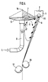
- Fig. 1 shows an annular spinneret 1, which is installed in a housing 4 and contains nozzle bores 111.
- circular filaments 9 emerge from the nozzle bores 111 and are drawn off via the discharge roller 18.
- the filaments 9 are bundled by two opposite preparation rollers 17 and 19, which simultaneously apply the preparation liquid necessary for the further process.
- Blown air L is conducted via a tube 8 arranged concentrically to the spinneret pack 1 to a blower nozzle 70 which essentially consists of a lower part 6 and an upper part 7.
- the blown air emerges radially outward from the orifice opening 16 and flows through the filaments 9 from the inside to the outside immediately after it emerges from the nozzle bores 111.
- the orifice opening 16 of the blower nozzle 70 is ring-shaped in accordance with the circular arrangement of the nozzle bores 111 and concentric with the spinneret pack 1 arranged.
- the melt P is fed to the spinneret pack 1 by means of a spinning pump 5, which feeds the melt P to the spinneret pack 1 via distributor channels 41 and distributes it evenly.
- the temperature uniformity required for a good melt distribution is ensured by an induction heating device, the induction coils 3 with a U-shaped iron core 32 and has a short-circuit ring 2.
- the short-circuit ring 2 is embedded in a recess 21 of the spinneret pack 1 and is directly connected to the spinneret pack 1 by screwing or the like, so that the heat generated in the short-circuit ring 2 is emitted directly to the spinneret pack 1.
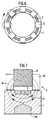
- the induction coils 3 are evenly distributed over the circumference of the short-circuit ring 2. Due to the U-shaped iron core 32 arranged above the recess 21 in the nozzle packet 1, magnetic field lines M arise when current flows through, which flood the ferromagnetic material of the nozzle packet 1 in the radial direction (FIG. 7).
- the spinneret pack 1 and the induction coils 3 are arranged in a housing 4 of the spinning device, but are each fixed independently of one another, so that the spinneret pack 1 can be installed on its own without impairing the induction coils 3.
- the air supply from below which is required due to the use of a central melt distribution, is directed by a special blowing nozzle 70 against the filaments 9 emerging from the nozzle bores 111.
- the blowing nozzle 70 is designed to guide the blowing air L in a special way.
- the upper part 7 and the lower part 6 together form a duct for the air, the air duct in the lower part 6 shortly before the mouth opening 16 having a curvature 61 through which the air flow is deflected towards the outlet of the filaments 9 from the nozzle bores 111.
- the apex of the curvature 61 is therefore on the side remote from the nozzle bores 111.
- the flowing air compresses on the outside of the curvature 61 and thereby gets an increased speed.
- This speed profile is shown schematically in FIG. 3.
- a speed profile favorable for the flow through the filament sheet 9 can be achieved.
- a length of preferably two to four times the height distance H of the cross section of the mouth opening 16 has proven to be optimal .
- the cooling effect of the blown air L can of course also be increased by spraying water or a spin finish.
- spray nozzles 81 can be arranged either within the blown air line 8 and / or in a star shape around this line 8 (FIG. 4).
- the air circulation described above has a favorable effect.
- the blowing air L is conducted from below through the blowing air line 8 to the blowing nozzle 70.
- a deflection of the air flow by about 90 ° is necessary.
- the curvature 61 is preceded by a second curvature 71, the apex of which is located in the upper part 7 of the blowing nozzle 70.
- This upper part 7 extends upward in the shape of a roof or, in the case of a round design of the blow head, in the shape of a cone, so that there is sufficient space for the curve 71.
- the air flow emerging at the lower edge of the curvature 61 strikes the filament sheet 9 at a higher speed and at a greater distance from the nozzle outlet than the air flow arriving at a lower speed on the inner wall of the curvature 61 formed by the upper part 7, which the thread sheet 9 immediately after Exit from the nozzle bores 111 is detected on the entry side, while the filament sheet 9 on the exit side is detected by the higher air speed on the outside of the curve 61.
- the blowing nozzle 70 In order to be able to place the blowing nozzle 70 in the vertical direction with respect to the nozzle bores 111, the latter is equipped with an adjusting device which also allows the width of the orifice opening 16 to be adjusted.
- this adjustment mechanism is shown, with which the blowing air L can be adjusted exactly to the respective requirements.
- the blowing nozzle 700 is fixed radially via the centering 15, which is connected to the threaded piece 11 via the connecting rod 14.
- the height of the centering 15 is adjusted and moved into a centering recess 42 of the housing 4 (FIG. 1).
- the upper part 7 of the blowing nozzle 70 can now be adjusted in height so that the filaments 9 are cooled at the optimum time after exiting the nozzle bores 111.
- the position of the lower part 6 of the blowing nozzle 70 can be changed via the thread 11 and the compensating piece 12.
- the mouth opening 16 can be adjusted in such a way that the necessary cooling section until the filaments 9 cool is available for each titer, each material and each production speed.
- the correct setting of the mouth opening 16 in connection with the flow rate of the blown air L makes it possible to avoid unnecessarily high air consumption and still achieve the required cooling effect.
- the high air velocities necessary to overcome the resulting penetration resistance can be generated in this way by reducing the orifice opening 16.
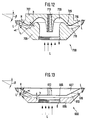
- the blowing nozzle 700 consists of an upper part 707 and a lower part 706.
- the lower part 706 is connected to a blowing air line 8, from which the blowing air flow L enters the blowing nozzle 700.
- the blowing air nozzle 700 is, for example, an annular nozzle in which the blowing air L enters centrally from below and flows from the center of the blowing nozzle 700 to the ring-shaped mouth opening 716, where it leaves the blowing nozzle 700 and exits against the bores 111 of the spinnerets 1 (not shown here) Threads 9 flows.
- the blown air flow L first passes a deflection 720, which is followed by a constriction 705 and which in turn is followed by a curve 710 before the blown air flow L has reached the mouth opening 716.
- the constriction is formed by reducing the height distance h between the air guiding walls of the blowing nozzle 700.
- the blown air then emerges radially outward from the mouth opening 716 and flows through the filaments 9 (not shown here) immediately after they emerge from the nozzle bores from the inside Outside.
- the mouth opening 716 of the blowing nozzle 700 is ring-shaped in accordance with the circular arrangement of the nozzle bores and is arranged concentrically with the spinneret pack 1 (not shown here). As already mentioned, it has a cross section with a greater height distance than the constriction 705.
- the blown air line 8 in turn has a cross section with a larger height distance than the constriction 705 when it enters the blower nozzle 700, so that this constriction transforms the blown air flow L in the way that happens is flattened. It has been shown that this reshaping achieves a considerable improvement in the distribution of the flow velocity over the circumference of the orifice opening 716 of the blowing nozzle 700.
- Turbulence in the inflow may be calmed down by this reduction and subsequent increase in the height distance, so that the flow velocity becomes more uniform over the entire area of the orifice opening 716.
- the curvatures 720 and 710 achieve a speed profile which is favorable for the flow of the filament sheet, as already described above.
- the blowing nozzle 700 In order to be able to place the blowing nozzle 700 in the vertical direction with respect to the nozzle bores 111, the latter is equipped with an adjusting device as described in connection with the embodiment according to FIG. 5.
- This adjusting device permits the setting of the width of the orifice opening 716.
- the blowing nozzle 700 is fixed radially in the same way via a centering 15, which is connected to the threaded piece 11 via a connecting rod 14.
- the connecting rod 14 has a thread 13 which engages in the threaded bore 713 of the upper part. Via this thread 713, the upper part 707 of the blowing nozzle 700 can be adjusted in height so that the filaments 9 are cooled at the optimum time after exiting the nozzle bores 111.
- the orifice opening 716 can be adjusted so that the necessary cooling distance is available for each titer, each material and each throughput until the filaments 9 have cooled.
- the correct setting of the mouth opening 716 in connection with the flow rate of the blown air L makes it possible to avoid unnecessarily high air consumption and still achieve the required cooling effect.
- the high air velocities necessary to overcome the resulting penetration resistance can be generated in this way by reducing the orifice opening 716.
- This adjustment of the mouth opening 716 automatically adapts to the narrowing 705 when the lower part 706 is adjusted relative to the upper part 707, so that the narrowing 705 with respect to the mouth opening 716 always has a cross section with a smaller height h than the mouth opening 716, even if the latter is reduced in size becomes.
- This constriction 705 has proven to be extremely effective. Experiments have shown that the coefficient of variation of the titer alone could be reduced by 20%. The amount of blown air was surprisingly reduced by about half. This constriction 705 not only has a significant influence on the homogenization of the blown air flow in connection with the curvature 710 upstream of the orifice opening 716, but also has an effect on a conventional blowing nozzle without the curvature 710 according to the invention (e.g. DE-OS 2 920 676).
- Fig. 13 shows another embodiment of the invention, which is particularly characterized in that it is much easier and cheaper to manufacture.
- the blowing nozzle 600 also consists of an upper part 607 and a lower part 606, the blowing air flow L from the blowing air line 8 entering the lower part 606.
- the upper part 607 and the lower part 606 are plate-shaped.
- the distance between the upper and lower part forms a constriction 605 which extends at right angles to the blown air line 8.
- This constriction 605 is followed by an angular curvature 620, through which the blast air flow is deflected, so that the desired speed profile is achieved at the mouth opening 616.
- With vertical adjustment of the upper part 607 against the lower part 606, the height distance h of the cross section of the constriction 605 and the height distance H of the mouth opening 616 are simultaneously reduced, so that the flow conditions are approximately maintained.
- the depth of the recess 21 in the nozzle packet 1 can match the thickness of the short-circuit ring 2, so that a flush closure is achieved, but a cover ring for the short-circuit ring 2 can also be provided, which is also received by the recess 21 in the nozzle packet 1.
- the induction coils 3 essentially consist of the horseshoe-shaped iron core 32 and the winding 31.
- the recess 21 in the spinneret pack 1 allows two pronounced poles to be formed, which face the pole faces of the induction coils 3. With this arrangement, the magnetic field lines M are bundled and directed (FIG. 7).
- the induction coils 3 can be effectively accommodated in a simple manner without complex redesign of the nozzle package 1.
- the induction coils 3 are now excited by alternating current, preferably in the range of the usual network frequencies of 50 or 60 Hz, then a current is induced in the circumferential direction of the nozzle packet 1 according to the "generator rule (right hand)". So that this current can flow in the circumferential direction, as desired, all induction coils 3 must work in phase, ie the Current in the coils must reach its minimum and maximum values at the same time and flow through all coils in the same direction.
- the strength of the current induced in the nozzle pack 1 depends on the flux density in the magnetic circuit and on the ohmic resistance of the material used (eg material no. 1.4057 with 0.7 ⁇ mm 2nd ) m from.
- the short-circuit component P K of the total power is asked, which consists of the power of the short-circuit current and the power of all eddy currents P w .
- the heat in the short-circuit ring 2 is evenly distributed over the entire circumference, because the current strength in the closed ring is the same in each cross-section and because this ring 2 in principle has no different cross-sections. The heat resulting from the short-circuit current is therefore transferred very evenly to the nozzle packet 1.
- the achievable heating output also increases.
- the nozzle bores 111 and thus the entire nozzle package 1 are affected by external disturbances, such as locally different cooling, caused by the blowing air speed, which is never quite evenly distributed. Therefore, an unchanged uniform temperature distribution over the nozzle plate can only be achieved if the nozzle packet 1 is divided along its circumference into heating zones (sectors), the temperature of which can be individually regulated. The same temperature setpoint is generally specified for each sector.
- the ON time of the coil in question is increased or decreased, depending on whether the local temperature is lower or higher than the target temperature.
- the eddy current output decreases in accordance with the number of coils 3 switched off, while the short-circuit power decreases exponentially, which can be attributed to the magnetic flux, which is becoming less and less and the induction in the short-circuit ring 2 in the spinneret package 1, which is therefore decreasing.
- Using programmed controllers it is possible to regulate the temperature of a nozzle package 1 described above in the individual heating zones precisely to the desired setpoint.
- Semiconductors such as triac or the like are preferably used as the switching element for this purpose.
- the induction coils 3 essentially consist of the horseshoe-shaped iron core 32 and the winding 31.
- Fig. 6 shows a top view of the arrangement of the induction coils 3 evenly distributed over the circumference of the ring nozzle package 1, which are designed for the usual AC voltage.
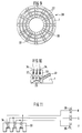
- FIGS. 9, 10 and 11 Another embodiment is shown in FIGS. 9, 10 and 11, which is suitable for 3-phase or three-phase current.
- three short-circuit rings 22 are embedded next to each other. They run concentrically because the nozzle assembly 1 is ring-shaped.
- the three short-circuit rings 22 run in a straight line and parallel to one another.
- Induction coils 3, which each have three windings 34 wound on a horseshoe-shaped iron core 33, the pole pieces of which are located between the recesses 23 above the nozzle packet 1, are arranged over the three short-circuit rings 22, evenly distributed over the circumference of the nozzle packet 1.
- Each of the windings 34 of the induction coil 30 is connected to the phase R or S or T via its own switching element 35, so that each winding 34 can be switched on and off individually. In this way, a particularly fine-grained regulation of the heat output, in particular also in the radial direction, is achieved.
- an induction heater has advantages, firstly because the induction coils 3, 30 as heating elements are completely independent of the spinneret package 1, so that no connections are removed when they are replaced must be, as is necessary with the usual electrical or steam heating systems. On the other hand, there is an absolutely uniform heating, since different thermal bridge gaps and the like play no role after the heat is generated directly where it is needed.
- the induction heater according to the invention also has the advantage that the temperature can also be regulated in a very fine-tuned manner even locally.
- the desired temperature is maintained by temperature sensors and the switching device 35 described above, in that the individual induction coils 3, 30 or also individual windings 34 are switched on and off.
- a particularly fine temperature control is also achieved, for example, in that the switching device 35 switches the induction coils 3, 30 on and off in a short cycle sequence.
- Each individual induction coil 3, 30 can be switched on and off individually.
- the device can also be designed so that all induction coils 3, 30 are switched on and off simultaneously.
- a certain temperature is maintained by the set switching frequency. By switching off individual induction coils 3, 30, less current is generated due to the excitation, so that less heating occurs in the short-circuit ring 2 or 22, but this is evenly distributed over the entire ring.
- the invention has been described using examples in which the air is supplied from below. However, the invention can also be used with the same advantage for air supply from above, as shown in FIG. 8. In this case it is it is not necessary to connect a second curve 71 upstream, since the air flow is already coming from above and the desired flow profile is generated by the curve 61.
- the air is supplied from below.
- the air can also be supplied from above.
- the bottom part 610 is a closed plate.
- the blown air line 8 is connected to the upper part 607.
- the invention is also not limited to a ring nozzle package 1 or to a blowing nozzle 70, 600 or 700 with an annular opening 16, 616 or 716. Even in a row arrangement, it is easily possible to generate a corresponding flow profile or to provide a corresponding constriction 605, 705 in order to be able to use large-area nozzle plates. It is e.g. readily conceivable that the cross sections shown in FIG. 1 or also FIGS. 12 and 13 relate to two nozzle packs 1 arranged in series, which are arranged symmetrically to the blowing nozzle 70 or 600 or 700, the two slot-shaped rows of the nozzle bore 111 assigned mouth openings 16 or 616 or 716.
- An induction heater can also be fitted here, in which the induction coils 3 and 30 are then of course arranged in series over the area over which the spinneret pack 1 extends.
- the short-circuit ring 2 or 22 is in this case not arranged as a ring, but in series with the nozzle bores 111.
- the mode of operation is otherwise the same as described above for the annular arrangement.
- the linear arrangement has the advantage that when the air is supplied from below, no sword or other division by the blown air supply is required.
- the blown air L can be supplied between the filament sets 9 emerging from the nozzle bores 111.
- a supply of the blown air L is also both possible from above and from below, as already described for the annular arrangement according to FIG. 8.
Landscapes
- Engineering & Computer Science (AREA)
- Mechanical Engineering (AREA)
- Textile Engineering (AREA)
- Physics & Mathematics (AREA)
- Thermal Sciences (AREA)
- Spinning Methods And Devices For Manufacturing Artificial Fibers (AREA)
Priority Applications (1)
| Application Number | Priority Date | Filing Date | Title |
|---|---|---|---|
| EP01103488A EP1122343A1 (fr) | 1995-11-30 | 1996-11-21 | Dispositif pour le filage au fondu |
Applications Claiming Priority (2)
| Application Number | Priority Date | Filing Date | Title |
|---|---|---|---|
| DE19544662A DE19544662A1 (de) | 1995-11-30 | 1995-11-30 | Schmelzespinnvorrichtung |
| DE19544662 | 1995-11-30 |
Related Child Applications (1)
| Application Number | Title | Priority Date | Filing Date |
|---|---|---|---|
| EP01103488A Division EP1122343A1 (fr) | 1995-11-30 | 1996-11-21 | Dispositif pour le filage au fondu |
Publications (3)
| Publication Number | Publication Date |
|---|---|
| EP0781877A2 true EP0781877A2 (fr) | 1997-07-02 |
| EP0781877A3 EP0781877A3 (fr) | 1998-04-29 |
| EP0781877B1 EP0781877B1 (fr) | 2002-07-17 |
Family
ID=7778822
Family Applications (2)
| Application Number | Title | Priority Date | Filing Date |
|---|---|---|---|
| EP96118669A Expired - Lifetime EP0781877B1 (fr) | 1995-11-30 | 1996-11-21 | Dispositif pour le filage au fondu |
| EP01103488A Withdrawn EP1122343A1 (fr) | 1995-11-30 | 1996-11-21 | Dispositif pour le filage au fondu |
Family Applications After (1)
| Application Number | Title | Priority Date | Filing Date |
|---|---|---|---|
| EP01103488A Withdrawn EP1122343A1 (fr) | 1995-11-30 | 1996-11-21 | Dispositif pour le filage au fondu |
Country Status (5)
| Country | Link |
|---|---|
| US (2) | US6062838A (fr) |
| EP (2) | EP0781877B1 (fr) |
| JP (1) | JPH09268420A (fr) |
| CN (1) | CN1157861A (fr) |
| DE (2) | DE19544662A1 (fr) |
Families Citing this family (16)
| Publication number | Priority date | Publication date | Assignee | Title |
|---|---|---|---|---|
| DE19821778B4 (de) * | 1998-05-14 | 2004-05-06 | Ems-Inventa Ag | Vorrichtung und Verfahren zur Herstellung von Mikrofilamenten von hoher Titer-Gleichmäßigkeit aus thermoplastischen Polymeren |
| DE19829272A1 (de) * | 1998-07-01 | 2000-01-05 | Rieter Automatik Gmbh | Heizsystem für schmelzeführende Teile |
| DE10105440A1 (de) * | 2001-02-07 | 2002-08-08 | Neumag Gmbh & Co Kg | Vorrichtung zum Schmelzspinnen und Kühlen einer Filamentschar |
| DE10134003A1 (de) * | 2001-07-12 | 2003-01-23 | Neumag Gmbh & Co Kg | Vorrichtung zum Schmelzspinnen und Kühlen einer Filamentschar |
| CN101845674B (zh) * | 2010-06-07 | 2011-09-28 | 扬州华美丙纶纺织有限公司 | 二层环吹风纤维喷丝头 |
| DE102011018223A1 (de) * | 2011-04-19 | 2012-10-25 | Trützschler Nonwovens Gmbh | Spinndüse zum Nassspinnen |
| DE102012012061A1 (de) * | 2012-06-15 | 2013-12-19 | Automatik Plastics Machinery Gmbh | Vorrichtung zum Granulieren von Schmelzematerial |
| DE102012215749A1 (de) * | 2012-09-05 | 2014-03-06 | Robert Bosch Gmbh | Verfahren und Vorrichtung zur Herstellung dreidimensionaler Objekte mit freitragenden und/oder überhängenden Teilen |
| JP6037552B2 (ja) * | 2012-10-01 | 2016-12-07 | トクデン株式会社 | 紡糸用パック加熱装置及び溶融紡糸装置 |
| CN104947215A (zh) * | 2015-07-29 | 2015-09-30 | 吴江市华运纺织品有限公司 | 一种用于大提花织物的熔体纺丝装置 |
| DE102016004715A1 (de) * | 2016-04-19 | 2017-10-19 | Oerlikon Textile Gmbh & Co. Kg | Vorrichtung zum Abkühlen einer ringförmigen extrudierten Filamentschar |
| AU2017257537B2 (en) | 2016-04-25 | 2022-08-11 | Cytec Industries Inc. | Spinneret assembly for spinning polymeric fibers |
| CN110257935B (zh) * | 2019-07-10 | 2022-02-15 | 广东工业大学 | 一种用于离心纺丝的储液与喷液的自动调节装置 |
| KR102154308B1 (ko) * | 2019-07-12 | 2020-09-09 | 주식회사 메이스터 | 기능성 여재를 섬유사에 부착하는 기능성 여재 부착장치 |
| JP2021055235A (ja) * | 2019-10-02 | 2021-04-08 | Tmtマシナリー株式会社 | 紡糸生産設備 |
| CN118996646A (zh) * | 2023-05-22 | 2024-11-22 | 日本Tmt机械株式会社 | 纺丝卷取设备以及穿丝辅助装置 |
Citations (4)
| Publication number | Priority date | Publication date | Assignee | Title |
|---|---|---|---|---|
| DE2920676A1 (de) | 1978-05-24 | 1979-11-29 | Corima Spa | Extruderkopf fuer die herstellung synthetischer und entsprechender textil- faeden |
| EP0517994A2 (fr) | 1991-06-14 | 1992-12-16 | FARE' S.p.A. | Dispositif pour l'extrusion de polymères |
| EP0536497A2 (fr) | 1991-08-09 | 1993-04-14 | The Bouligny Company | Méthode et dispositif pour le refroidissement de filaments |
| DE4312309C2 (de) | 1993-04-15 | 1995-06-08 | Reifenhaeuser Masch | Verfahren und Vorrichtungen zur Herstellung eines Spinnvlies-Flächenproduktes |
Family Cites Families (19)
| Publication number | Priority date | Publication date | Assignee | Title |
|---|---|---|---|---|
| US2721371A (en) | 1952-02-01 | 1955-10-25 | Ici Ltd | Packaging of yarns and filaments |
| DE1273174B (de) * | 1966-11-03 | 1968-07-18 | Vickers Zimmer Ag | Vorrichtung zum Spinnen von Faeden, Baendern oder Straengen aus einer Schmelze oder einer Loesung aus hoeheren linearen Polymeren |
| FR1588880A (fr) * | 1968-09-06 | 1970-03-16 | ||
| US3583027A (en) * | 1968-11-15 | 1971-06-08 | Monsanto Co | Pedestal configuration for spinning low-viscosity melts |
| US3593775A (en) * | 1969-04-11 | 1971-07-20 | Monsanto Co | Heat transfer means in inviscid melt spinning apparatus |
| US3584678A (en) * | 1969-07-28 | 1971-06-15 | Monsanto Chemicals | Orifice plate for spinning fine diameter wire |
| GB1498184A (en) * | 1974-11-13 | 1978-01-18 | Owens Corning Fiberglass Corp | Method and apparatus for forming glass-fibres |
| US4173443A (en) * | 1977-06-01 | 1979-11-06 | Celanese Corporation | Spray spinning nozzle having convergent gaseous jets |
| JPS5766112A (en) * | 1980-10-03 | 1982-04-22 | Teijin Ltd | Equipment for melt spinning |
| DE3318096C1 (de) * | 1983-05-18 | 1984-12-20 | Automatik Apparate-Maschinenbau H. Hench Gmbh, 8754 Grossostheim | Vorrichtung zum Kühlen von aus Spinndüsen extrudierten Kunststoffäden |
| US4988270A (en) | 1985-09-18 | 1991-01-29 | Ems-Inventa Ag | Apparatus for cooling and conditioning melt-spun material |
| DE3713862A1 (de) * | 1987-04-25 | 1988-11-10 | Reifenhaeuser Masch | Verfahren und spinnvliesanlage zur herstellung eines spinnvlieses aus synthetischem endlosfilament |
| DE3901518A1 (de) * | 1989-01-20 | 1990-07-26 | Fleissner Maschf Ag | Verfahren zum kuehlen von aus spinnduesen austretenden filamenten |
| DE3927254A1 (de) * | 1989-08-18 | 1991-02-21 | Reifenhaeuser Masch | Verfahren und spinnduesenaggregat fuer die herstellung von kunststoff-faeden und/oder kunststoff-fasern im zuge der herstellung von einem spinnvlies aus thermoplastischem kunststoff |
| US5536157A (en) * | 1991-03-04 | 1996-07-16 | Ems-Inventa Ag.G. | Apparatus for cooling melt-spun filaments |
| US5292239A (en) * | 1992-06-01 | 1994-03-08 | Fiberweb North America, Inc. | Apparatus for producing nonwoven fabric |
| DE9210599U1 (de) | 1992-08-08 | 1993-12-09 | Robert Bosch Gmbh, 70469 Stuttgart | Bandschleifer |
| AT402738B (de) * | 1993-07-28 | 1997-08-25 | Chemiefaser Lenzing Ag | Spinndüse |
| TW311945B (fr) | 1994-11-23 | 1997-08-01 | Barmag Barmer Maschf |
-
1995
- 1995-11-30 DE DE19544662A patent/DE19544662A1/de not_active Withdrawn
-
1996
- 1996-11-21 DE DE59609449T patent/DE59609449D1/de not_active Expired - Fee Related
- 1996-11-21 EP EP96118669A patent/EP0781877B1/fr not_active Expired - Lifetime
- 1996-11-21 EP EP01103488A patent/EP1122343A1/fr not_active Withdrawn
- 1996-11-29 CN CN96123911A patent/CN1157861A/zh active Pending
- 1996-12-02 JP JP8322012A patent/JPH09268420A/ja active Pending
-
1998
- 1998-05-07 US US09/073,979 patent/US6062838A/en not_active Expired - Fee Related
- 1998-05-07 US US09/073,978 patent/US6176696B1/en not_active Expired - Fee Related
Patent Citations (5)
| Publication number | Priority date | Publication date | Assignee | Title |
|---|---|---|---|---|
| DE2920676A1 (de) | 1978-05-24 | 1979-11-29 | Corima Spa | Extruderkopf fuer die herstellung synthetischer und entsprechender textil- faeden |
| US4259048A (en) | 1978-05-24 | 1981-03-31 | Mario Miani | Extrusion head for producing synthetic and the like textile yarns |
| EP0517994A2 (fr) | 1991-06-14 | 1992-12-16 | FARE' S.p.A. | Dispositif pour l'extrusion de polymères |
| EP0536497A2 (fr) | 1991-08-09 | 1993-04-14 | The Bouligny Company | Méthode et dispositif pour le refroidissement de filaments |
| DE4312309C2 (de) | 1993-04-15 | 1995-06-08 | Reifenhaeuser Masch | Verfahren und Vorrichtungen zur Herstellung eines Spinnvlies-Flächenproduktes |
Also Published As
| Publication number | Publication date |
|---|---|
| CN1157861A (zh) | 1997-08-27 |
| EP0781877A3 (fr) | 1998-04-29 |
| US6062838A (en) | 2000-05-16 |
| US6176696B1 (en) | 2001-01-23 |
| DE59609449D1 (de) | 2002-08-22 |
| DE19544662A1 (de) | 1997-06-05 |
| JPH09268420A (ja) | 1997-10-14 |
| EP0781877B1 (fr) | 2002-07-17 |
| EP1122343A1 (fr) | 2001-08-08 |
Similar Documents
| Publication | Publication Date | Title |
|---|---|---|
| EP0781877B1 (fr) | Dispositif pour le filage au fondu | |
| EP0671492B1 (fr) | Utilisation d'une filière pour la fabrication de fils cellulosiques | |
| EP3692188B1 (fr) | Dispositif permettant l'extrusion de filaments et la fabrication de non-tissés meltspun | |
| DE69109584T2 (de) | Luftsystem für eine Spinndüse zum Schmelzblasspinnen. | |
| EP1902164B1 (fr) | Dispositif de filature et procede pour produire des fils fins par epissurage afin d'obtenir un nontisse, et nontisse susceptible d'etre obtenu ainsi | |
| DE4312309C2 (de) | Verfahren und Vorrichtungen zur Herstellung eines Spinnvlies-Flächenproduktes | |
| DE102007031755A1 (de) | Verfahren und Vorrichtung zum Schmelzspinnen eines synthetischen multifilen Fadens | |
| DE60108145T2 (de) | Vorrichtung und verfahren zur herstellung eines verbundfadens | |
| EP1637632A1 (fr) | Dispositif pour la production de filaments en matériau thermoplastique | |
| DE2717750A1 (de) | Verfahren und vorrichtung zur herstellung von profilen mit hochfrequenzbeheizung | |
| DE1959034B2 (de) | Anlage zum kontinuierlichen herstellen und aufwickeln von endlosen synethetischen faeden | |
| DE4220915A1 (de) | Verfahren und Vorrichtung zur Herstellung synthetischer Endlosfilamente | |
| EP0455897A1 (fr) | Dispositif pour la fabrication de fibres trés fines | |
| EP2971293A1 (fr) | Dispositif de filage à chaud, d'étirage et d'enroulement de plusieurs fils synthétiques | |
| EP2783028A1 (fr) | Dispositif de fabrication d'un câble de filature | |
| DE2218239C3 (de) | Vorrichtung zum Schmelzspinnen von Filamenten aus einem synthetischen Polymerisat | |
| EP0826802A1 (fr) | Procédé de filature des fils multifilaments | |
| DE102004039510A1 (de) | Vorrichtung und Verfahren zum Schmelzspinnen, Abziehen, Behandeln und Aufwickeln mehrerer synthetischer Fäden | |
| EP0931026A1 (fr) | Dispositif de filage de fibres de verre | |
| EP0731196A1 (fr) | Procédé pour le filage, l'étirage et le bobinage d'un fil synthétique | |
| DE2732012C2 (de) | Verfahren zur Herstellung von Glasfasern | |
| EP0752020B1 (fr) | Procede et dispositif permettant de refroidir des filaments files en fusion | |
| WO1994025653A1 (fr) | Procede d'etirage | |
| DE1660311B2 (de) | Verfahren zum Herstellen von Fäden und Vorrichtung zur Durchführung des Verfahrens | |
| DE2553069B2 (de) | Schlitzdüse zum Herstellen einer Polymerfolie gleichmäßiger Dicke |
Legal Events
| Date | Code | Title | Description |
|---|---|---|---|
| PUAI | Public reference made under article 153(3) epc to a published international application that has entered the european phase |
Free format text: ORIGINAL CODE: 0009012 |
|
| AK | Designated contracting states |
Kind code of ref document: A2 Designated state(s): CH DE FR GB IT LI |
|
| PUAL | Search report despatched |
Free format text: ORIGINAL CODE: 0009013 |
|
| AK | Designated contracting states |
Kind code of ref document: A3 Designated state(s): CH DE FR GB IT LI |
|
| 17P | Request for examination filed |
Effective date: 19981020 |
|
| 17Q | First examination report despatched |
Effective date: 19981211 |
|
| GRAG | Despatch of communication of intention to grant |
Free format text: ORIGINAL CODE: EPIDOS AGRA |
|
| GRAG | Despatch of communication of intention to grant |
Free format text: ORIGINAL CODE: EPIDOS AGRA |
|
| GRAG | Despatch of communication of intention to grant |
Free format text: ORIGINAL CODE: EPIDOS AGRA |
|
| GRAH | Despatch of communication of intention to grant a patent |
Free format text: ORIGINAL CODE: EPIDOS IGRA |
|
| GRAH | Despatch of communication of intention to grant a patent |
Free format text: ORIGINAL CODE: EPIDOS IGRA |
|
| GRAA | (expected) grant |
Free format text: ORIGINAL CODE: 0009210 |
|
| AK | Designated contracting states |
Kind code of ref document: B1 Designated state(s): CH DE FR GB IT LI |
|
| REG | Reference to a national code |
Ref country code: GB Ref legal event code: FG4D Free format text: NOT ENGLISH |
|
| REG | Reference to a national code |
Ref country code: CH Ref legal event code: EP |
|
| REF | Corresponds to: |
Ref document number: 59609449 Country of ref document: DE Date of ref document: 20020822 |
|
| PG25 | Lapsed in a contracting state [announced via postgrant information from national office to epo] |
Ref country code: GB Free format text: LAPSE BECAUSE OF NON-PAYMENT OF DUE FEES Effective date: 20021121 |
|
| GBT | Gb: translation of ep patent filed (gb section 77(6)(a)/1977) |
Effective date: 20021101 |
|
| PG25 | Lapsed in a contracting state [announced via postgrant information from national office to epo] |
Ref country code: LI Free format text: LAPSE BECAUSE OF NON-PAYMENT OF DUE FEES Effective date: 20021130 Ref country code: CH Free format text: LAPSE BECAUSE OF NON-PAYMENT OF DUE FEES Effective date: 20021130 |
|
| ET | Fr: translation filed | ||
| PLBE | No opposition filed within time limit |
Free format text: ORIGINAL CODE: 0009261 |
|
| STAA | Information on the status of an ep patent application or granted ep patent |
Free format text: STATUS: NO OPPOSITION FILED WITHIN TIME LIMIT |
|
| PG25 | Lapsed in a contracting state [announced via postgrant information from national office to epo] |
Ref country code: DE Free format text: LAPSE BECAUSE OF NON-PAYMENT OF DUE FEES Effective date: 20030603 |
|
| 26N | No opposition filed |
Effective date: 20030422 |
|
| GBPC | Gb: european patent ceased through non-payment of renewal fee | ||
| REG | Reference to a national code |
Ref country code: CH Ref legal event code: PL |
|
| PG25 | Lapsed in a contracting state [announced via postgrant information from national office to epo] |
Ref country code: FR Free format text: LAPSE BECAUSE OF NON-PAYMENT OF DUE FEES Effective date: 20030731 |
|
| REG | Reference to a national code |
Ref country code: FR Ref legal event code: ST |
|
| PG25 | Lapsed in a contracting state [announced via postgrant information from national office to epo] |
Ref country code: IT Free format text: LAPSE BECAUSE OF NON-PAYMENT OF DUE FEES Effective date: 20051121 |