EP0781895A1 - Verfahren und Vorrichtung zum Bohren von unterirdischen Strukturen mit variablerGrösse des Querschnittes - Google Patents
Verfahren und Vorrichtung zum Bohren von unterirdischen Strukturen mit variablerGrösse des Querschnittes Download PDFInfo
- Publication number
- EP0781895A1 EP0781895A1 EP96110771A EP96110771A EP0781895A1 EP 0781895 A1 EP0781895 A1 EP 0781895A1 EP 96110771 A EP96110771 A EP 96110771A EP 96110771 A EP96110771 A EP 96110771A EP 0781895 A1 EP0781895 A1 EP 0781895A1
- Authority
- EP
- European Patent Office
- Prior art keywords
- machine
- main machine
- auxiliary machine
- sectional area
- cross sectional
- Prior art date
- Legal status (The legal status is an assumption and is not a legal conclusion. Google has not performed a legal analysis and makes no representation as to the accuracy of the status listed.)
- Granted
Links
- 238000009412 basement excavation Methods 0.000 title claims abstract description 36
- 238000000034 method Methods 0.000 title claims abstract description 21
- 230000000295 complement effect Effects 0.000 claims 1
- 238000010276 construction Methods 0.000 description 11
- XLYOFNOQVPJJNP-UHFFFAOYSA-N water Substances O XLYOFNOQVPJJNP-UHFFFAOYSA-N 0.000 description 4
- 238000007796 conventional method Methods 0.000 description 1
- 238000005516 engineering process Methods 0.000 description 1
- 230000001681 protective effect Effects 0.000 description 1
- 238000000926 separation method Methods 0.000 description 1
- 239000007787 solid Substances 0.000 description 1
Images




Classifications
-
- E—FIXED CONSTRUCTIONS
- E21—EARTH OR ROCK DRILLING; MINING
- E21D—SHAFTS; TUNNELS; GALLERIES; LARGE UNDERGROUND CHAMBERS
- E21D9/00—Tunnels or galleries, with or without linings; Methods or apparatus for making thereof; Layout of tunnels or galleries
- E21D9/10—Making by using boring or cutting machines
- E21D9/11—Making by using boring or cutting machines with a rotary drilling-head cutting simultaneously the whole cross-section, i.e. full-face machines
- E21D9/112—Making by using boring or cutting machines with a rotary drilling-head cutting simultaneously the whole cross-section, i.e. full-face machines by means of one single rotary head or of concentric rotary heads
- E21D9/113—Making by using boring or cutting machines with a rotary drilling-head cutting simultaneously the whole cross-section, i.e. full-face machines by means of one single rotary head or of concentric rotary heads having a central part for making a pilot tunnel and a follow-up part for enlarging the pilot tunnel
-
- E—FIXED CONSTRUCTIONS
- E21—EARTH OR ROCK DRILLING; MINING
- E21D—SHAFTS; TUNNELS; GALLERIES; LARGE UNDERGROUND CHAMBERS
- E21D9/00—Tunnels or galleries, with or without linings; Methods or apparatus for making thereof; Layout of tunnels or galleries
- E21D9/06—Making by using a driving shield, i.e. advanced by pushing means bearing against the already placed lining
- E21D9/08—Making by using a driving shield, i.e. advanced by pushing means bearing against the already placed lining with additional boring or cutting means other than the conventional cutting edge of the shield
- E21D9/0874—Making by using a driving shield, i.e. advanced by pushing means bearing against the already placed lining with additional boring or cutting means other than the conventional cutting edge of the shield with rotary drilling heads having variable diameter
-
- E—FIXED CONSTRUCTIONS
- E21—EARTH OR ROCK DRILLING; MINING
- E21D—SHAFTS; TUNNELS; GALLERIES; LARGE UNDERGROUND CHAMBERS
- E21D9/00—Tunnels or galleries, with or without linings; Methods or apparatus for making thereof; Layout of tunnels or galleries
- E21D9/06—Making by using a driving shield, i.e. advanced by pushing means bearing against the already placed lining
- E21D9/08—Making by using a driving shield, i.e. advanced by pushing means bearing against the already placed lining with additional boring or cutting means other than the conventional cutting edge of the shield
- E21D9/0875—Making by using a driving shield, i.e. advanced by pushing means bearing against the already placed lining with additional boring or cutting means other than the conventional cutting edge of the shield with a movable support arm carrying cutting tools for attacking the front face, e.g. a bucket
- E21D9/0879—Making by using a driving shield, i.e. advanced by pushing means bearing against the already placed lining with additional boring or cutting means other than the conventional cutting edge of the shield with a movable support arm carrying cutting tools for attacking the front face, e.g. a bucket the shield being provided with devices for lining the tunnel, e.g. shuttering
-
- E—FIXED CONSTRUCTIONS
- E21—EARTH OR ROCK DRILLING; MINING
- E21D—SHAFTS; TUNNELS; GALLERIES; LARGE UNDERGROUND CHAMBERS
- E21D9/00—Tunnels or galleries, with or without linings; Methods or apparatus for making thereof; Layout of tunnels or galleries
- E21D9/10—Making by using boring or cutting machines
- E21D9/11—Making by using boring or cutting machines with a rotary drilling-head cutting simultaneously the whole cross-section, i.e. full-face machines
- E21D9/116—Making by using boring or cutting machines with a rotary drilling-head cutting simultaneously the whole cross-section, i.e. full-face machines by means of non-concentric rotary heads
Definitions
- the invention relates to a method and an apparatus of excavation for underground structures of variable cross sectional area.
- the cross sectional area of an underground structure is not always constant and will vary at some points, for example in a subway system, underground shopping malls, underground water and sewer lines or water reservoirs.
- a subway system for example, the cross sectional area of the portion comprising the train tracks is narrow, whereas it is wider for the station concourse and then narrows again for the tracks leaving the station on the other side. This pattern is repeated over the length of a subway line.
- a shield excavator is employed for the train tracks, whereas digging is used from the land surface down to the desired underground level for the corresponding stations.
- the object underlying the present invention is to resolve the problems arising with conventional construction methods and to provide a method and an apparatus of excavation for underground structures of variable cross sectional area by means of which the amount of land required for excavation work is minimized in order to significantly reduce the time and expense required for provisional construction work.
- a method and an apparatus are provided, wherein a shield excavator of large cross sectional area is used as a main machine, and another shield excavator of smaller cross sectional area than the main machine is used as an auxiliary machine. That portion of the underground structure having the large cross section is excavated using the main machine with the auxiliary machine housed inside thereof, whereas for that portion of the underground structure of small cross section, the auxiliary machine is advanced out of the main machine and excavation proceeds with the auxiliary machine only.
- the main machine is left on standby at the next portion of the structure of large cross section, and when the auxiliary machine reaches that point, it is re-inserted into the main machine; thereafter, excavation proceeds again using the main machine with the auxiliary machine housed inside and propelled jointly.
- the invention is by no means restricted to application in a subway system, but can be used to construct a large variety of constructions, including roadways, water and sewer lines, water reservoirs, shopping malls and other underground structures.
- various shield excavators of differing shape in cross section have been developed recently and are in practical use.
- the invention is not restricted to underground structures having a circular cross section, but can be applied to various other structures comprising elliptical, oval, rectangular, and gourd-shaped cross sectional areas.
- a shield jack 13 takes the reaction forces at a segment 14 assembled in the rear to propel the shield excavator forward. Also, a cutter 12 for boring into the ground is installed on the front face of the main machine 1.
- the main machine 1 is provided with a hollow cavern 11 used merely to house an auxiliary machine 2, as shown in Fig. 2. Accordingly, the hollow cavern 11 extends the full length of the main machine 1 from the front end to the tail end, wherein its inner shape is identical to the outer shape of the auxiliary machine 2. In other words, if the auxiliary machine 2 is cylindrical, then the hollow cavern 11 is a cylindrical space.
- the tube-shaped hollow cavern 11 in the main machine 1 opens at the front face of the main machine 1. Accordingly, the cutter 12 provided at the front of the main machine 1 is not a solid circular disk, rather its center is cut away to the same dimension as the cross section of the hollow cavern 11 to form the ring cutter 12. Such a component is shown, for example, in Fig. 1 of the drawings.
- the outer diameter of the auxiliary machine 2 is virtually equal to the cross sectional area of this portion of small cross sectional area of the underground structure, for example the track portion of the subway; at the same time, the outer diameter of the auxiliary machine 2 is equal to the inner diameter of the hollow cavern 11 of the main machine 1.
- auxiliary machine 2 The internal configuration of the auxiliary machine 2 is virtually identical to that of a conventional shield excavator. As shown in Fig. 4, a shield jack 22 takes the reaction forces at a segment 23 assembled in the rear to propel the shield excavator forward. Also, a cutter 21 for boring into the ground is installed on the front face of the excavator forming the auxiliary machine 2.
- the cutter 21 of the auxiliary machine 2 is formed as a disk, in particular a circular disk.
- the outer edge of the cutter 21 can interlock with the ring cutter 12 of the main machine 1 such that the two cutters 12 and 21 rotate as a monolithic unit.
- auxiliary machine 2 uses its own jack 22, and a segment 23 of virtually the same dimension as the auxiliary machine 2 is assembled at the rear of the machine. That jack 22 takes the reaction forces at this segment 23 when the auxiliary machine 2 can move forwardly independently of the main machine 1.
- the diameter of a station portion of a subway is larger than the diameter of the track portion; hence, the station portion is excavated by means of the main machine 1 with the auxiliary machine 2 housed inside thereof and cooperating therewith.
- the disk cutter 21 of the auxiliary machine 2 is interlocked with the inner circumference of the ring cutter 12 of the main machine 1, and the two cutters 12 and 21 rotate together as a monolithic unit.
- a vertical shaft 3 is pre-built at the respective end of the large cross sectional area portion, for example a station portion. That is, when excavation of the station portion with the main machine 1 is completed, it advances into the shaft 3. At this point, excavation shifts to the track portion of smaller cross section. For this purpose, the operation of the main machine 1 is stopped inside the shaft 3, and the auxiliary machine 2 is withdrawn from its hollow cavern 11. This situation is shown in a diagrammatic manner in Fig. 2 and Fig. 3 and Fig. 4 of the drawings.
- a group of segments to take the reaction force is required to launch the auxiliary machine 2 out of the main machine 1.
- a reaction force bearing block is set inside the main machine 1 within which the segments are assembled.
- the jack presses against the segments to propel the auxiliary machine 2 forward.
- only the auxiliary machine 2 is used to excavate the portion of smaller cross sectional area, for example the track portion up to the next station.
- the main machine 1 from which the auxiliary machine 2 has been withdrawn remains inside the shaft 3 and is then pulled up to the surface. Then, the main machine 1 is transported over land to the start of the next portion of large cross sectional area, in particular the next station portion. At that point, the main machine 1 is lowered down another pre-built shaft 3 where it remains on standby until the arrival of the auxiliary machine 2. This situation is shown, for example, in Fig. 5 of the drawings. The transport and standby action is repeated in sequence for each of the shafts 3 provided along the underground construction.
- the main machine 1 is transported in one piece as indicated in Fig. 1.
- the invention is not limited to such a concept, rather the main machine needs not be transported in one piece. It can be temporarily dismantled into several segments which are then carried to the next shaft where the main machine 1 is reassembled. This situation is shown, for example, in Fig. 6 of the drawings.
- the auxiliary machine 2 completes excavation of the portion of smaller cross sectional area, for example the track portion, and arrives at the shaft 3 of the next station, see Fig. 5 of the drawings. It is then inserted into the hollow cavern 11 of the main machine 1 which has been on standby. At this point, the main machine 1 and the auxiliary machine 2 become immediately a monolithic unit which is used to excavate another station portion of larger diameter than the portion of the tracks.
- Such a configuration enables an immediate adjustment to a change in the cross section area of the portion being excavated.
- the combined apparatus comprising the main machine 1 and the auxiliary machine 2 reaches the end of the station portion where the cross sectional area is reduced again to that of the jack portion, the auxiliary machine 2 is launched out of the main machine 1.
- the main machine 1 and the auxiliary machine 2 can be used in various combinations as explained hereinafter.
- the technology and devices used in excavating elliptical, rectangular, oval, horseshoe-shaped and other tunnels of variable cross section employ copy cutters, swing cutters, planet cutters and other cutters which are known as such so that a detailed explanation is omitted here.
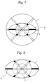
- Such combinations and configurations will be explained shortly with reference to Fig. 7 to Fig. 15 of the drawings.
- the black portions identified by the reference signs 31 in Fig. 7 to Fig. 15 represent telescopic cutters.
- Fig. 7 shows a constellation using a circular main machine 1 in which an auxiliary machine 2 is housed having an elliptical shape in cross section.
- Fig. 8 shows a constellation with an elliptical main machine 1 housing a circular auxiliary machine 2.
- the main machine 1 has a circular shape, whereas the shape of the auxiliary machine 2 is rectangular.
- Fig. 10 shows a configuration where the main machine 1 is of rectangular cross section, whereas the auxiliary machine 2 housed therein has a circular shape.
- Fig. 11 shows a configuration where the main machine 1 is of rectangular shape, wherein an auxiliary machine 2 of rectangular shape is housed therein.
- Fig. 12 shows a configuration where the main machine 1 has an elliptical shape, and the auxiliary machine 2 housed therein has also an elliptical shape.
- Fig. 13 shows a specific configuration where the main machine 1 is crescent-shaped, whereas the auxiliary machine 2 is of circular shape.
- Fig. 14 shows another specific configuration where the main machine 1 is of elliptical shape, whereas two auxiliary machines 2 of cylindrical shape are housed therein.
- Fig. 15 shows a configuration where the main machine 1 is of circular shape, wherein the auxiliary machine 2 is also of circular shape but mounted in an excentric manner.
Landscapes
- Engineering & Computer Science (AREA)
- Mining & Mineral Resources (AREA)
- Environmental & Geological Engineering (AREA)
- Life Sciences & Earth Sciences (AREA)
- General Life Sciences & Earth Sciences (AREA)
- Geochemistry & Mineralogy (AREA)
- Geology (AREA)
- Excavating Of Shafts Or Tunnels (AREA)
- Lining And Supports For Tunnels (AREA)
Applications Claiming Priority (3)
| Application Number | Priority Date | Filing Date | Title |
|---|---|---|---|
| JP35302495A JP3622161B2 (ja) | 1995-12-28 | 1995-12-28 | 断面積の異なる地下構造物の施工方法 |
| JP35302495 | 1995-12-28 | ||
| JP353024/95 | 1995-12-28 |
Publications (2)
| Publication Number | Publication Date |
|---|---|
| EP0781895A1 true EP0781895A1 (de) | 1997-07-02 |
| EP0781895B1 EP0781895B1 (de) | 2001-10-17 |
Family
ID=18428056
Family Applications (1)
| Application Number | Title | Priority Date | Filing Date |
|---|---|---|---|
| EP96110771A Expired - Lifetime EP0781895B1 (de) | 1995-12-28 | 1996-07-03 | Verfahren zum Bohren von unterirdischen Strukturen mit variabler Grösse des Querschnittes |
Country Status (3)
| Country | Link |
|---|---|
| EP (1) | EP0781895B1 (de) |
| JP (1) | JP3622161B2 (de) |
| DE (1) | DE69616001T2 (de) |
Cited By (3)
| Publication number | Priority date | Publication date | Assignee | Title |
|---|---|---|---|---|
| EP1314852A1 (de) * | 2001-11-21 | 2003-05-28 | Mitsubishi Heavy Industries, Ltd. | Tunnelvortriebsmaschine und Verfahren zu deren Wiedergewinnung |
| ES2270742A1 (es) * | 2006-12-04 | 2007-04-01 | Enia Tecnica Y Gestion S.L. | Procedimiento dispositivo para la realizacion de tuneles y complemento para tuneladora. |
| CN116696380A (zh) * | 2023-07-28 | 2023-09-05 | 中交二公局东萌工程有限公司 | 一种地下tbm拆机洞室的施工方法 |
Families Citing this family (4)
| Publication number | Priority date | Publication date | Assignee | Title |
|---|---|---|---|---|
| JP4611473B2 (ja) * | 1999-10-01 | 2011-01-12 | 株式会社熊谷組 | トンネル施工方法 |
| JP2003082978A (ja) * | 2001-09-12 | 2003-03-19 | Daiho Constr Co Ltd | トンネル築造方法及び親子シールド機 |
| JP4693799B2 (ja) * | 2007-02-21 | 2011-06-01 | 株式会社奥村組 | トンネル掘削機の組立方法 |
| JP4674711B2 (ja) * | 2009-09-04 | 2011-04-20 | 伊藤忠建機株式会社 | 掘進機 |
Citations (10)
| Publication number | Priority date | Publication date | Assignee | Title |
|---|---|---|---|---|
| US2864600A (en) * | 1955-08-08 | 1958-12-16 | Max B Kirkpatrick | Mining machine |
| GB961295A (en) * | 1959-07-07 | 1964-06-17 | Bade & Co Gmbh | A method of tunnelling and an installation and boring machine unit for performing the same |
| US3480327A (en) * | 1965-02-19 | 1969-11-25 | Kumagai Gumi Co Ltd | Excavation type shield with concentric rotary cutter barrels |
| US3639006A (en) * | 1970-02-12 | 1972-02-01 | Wirth Co Kg Masch Bohr | Machinery for driving tunnels, galleries or the like |
| US3643998A (en) * | 1970-04-20 | 1972-02-22 | Jacobs Associates | Tunneling machine for noncircular bores |
| GB2001684A (en) * | 1977-07-19 | 1979-02-07 | Mowlem & Co Ltd J | Tunnelling shields |
| JPH02210189A (ja) * | 1989-02-08 | 1990-08-21 | Shimizu Corp | シールド機 |
| EP0384065A1 (de) * | 1989-02-15 | 1990-08-29 | Zaidan Hohjin Doboku Kenkyu Center | Verfahren für den Schildvortrieb mit wählbarem Querschnitt und Maschine dafür |
| JPH04179796A (ja) * | 1990-11-14 | 1992-06-26 | Teito Kousokudo Kotsu Eidan | 地下鉄道のシールドトンネル掘削方法 |
| US5221160A (en) * | 1990-04-26 | 1993-06-22 | Shimizuo Construction Co. | Subterranean connecting method for construction of shield tunnel and connecting apparatus therefor |
-
1995
- 1995-12-28 JP JP35302495A patent/JP3622161B2/ja not_active Expired - Fee Related
-
1996
- 1996-07-03 DE DE69616001T patent/DE69616001T2/de not_active Expired - Fee Related
- 1996-07-03 EP EP96110771A patent/EP0781895B1/de not_active Expired - Lifetime
Patent Citations (10)
| Publication number | Priority date | Publication date | Assignee | Title |
|---|---|---|---|---|
| US2864600A (en) * | 1955-08-08 | 1958-12-16 | Max B Kirkpatrick | Mining machine |
| GB961295A (en) * | 1959-07-07 | 1964-06-17 | Bade & Co Gmbh | A method of tunnelling and an installation and boring machine unit for performing the same |
| US3480327A (en) * | 1965-02-19 | 1969-11-25 | Kumagai Gumi Co Ltd | Excavation type shield with concentric rotary cutter barrels |
| US3639006A (en) * | 1970-02-12 | 1972-02-01 | Wirth Co Kg Masch Bohr | Machinery for driving tunnels, galleries or the like |
| US3643998A (en) * | 1970-04-20 | 1972-02-22 | Jacobs Associates | Tunneling machine for noncircular bores |
| GB2001684A (en) * | 1977-07-19 | 1979-02-07 | Mowlem & Co Ltd J | Tunnelling shields |
| JPH02210189A (ja) * | 1989-02-08 | 1990-08-21 | Shimizu Corp | シールド機 |
| EP0384065A1 (de) * | 1989-02-15 | 1990-08-29 | Zaidan Hohjin Doboku Kenkyu Center | Verfahren für den Schildvortrieb mit wählbarem Querschnitt und Maschine dafür |
| US5221160A (en) * | 1990-04-26 | 1993-06-22 | Shimizuo Construction Co. | Subterranean connecting method for construction of shield tunnel and connecting apparatus therefor |
| JPH04179796A (ja) * | 1990-11-14 | 1992-06-26 | Teito Kousokudo Kotsu Eidan | 地下鉄道のシールドトンネル掘削方法 |
Non-Patent Citations (2)
| Title |
|---|
| PATENT ABSTRACTS OF JAPAN vol. 014, no. 510 (M - 1045) 8 November 1990 (1990-11-08) * |
| PATENT ABSTRACTS OF JAPAN vol. 016, no. 487 (M - 1323) 9 October 1992 (1992-10-09) * |
Cited By (5)
| Publication number | Priority date | Publication date | Assignee | Title |
|---|---|---|---|---|
| EP1314852A1 (de) * | 2001-11-21 | 2003-05-28 | Mitsubishi Heavy Industries, Ltd. | Tunnelvortriebsmaschine und Verfahren zu deren Wiedergewinnung |
| ES2270742A1 (es) * | 2006-12-04 | 2007-04-01 | Enia Tecnica Y Gestion S.L. | Procedimiento dispositivo para la realizacion de tuneles y complemento para tuneladora. |
| ES2270742B1 (es) * | 2006-12-04 | 2008-04-16 | Enia Tecnica Y Gestion S.L. | Procedimiento, dispositivo para la realizacion de tuneles y complemento para tuneladora. |
| WO2008068363A1 (es) * | 2006-12-04 | 2008-06-12 | Enia Tecnica Y Gestion, S.L. | Procedimiento, dispositivo para la realizacion de tuneles y complemento para tuneladora |
| CN116696380A (zh) * | 2023-07-28 | 2023-09-05 | 中交二公局东萌工程有限公司 | 一种地下tbm拆机洞室的施工方法 |
Also Published As
| Publication number | Publication date |
|---|---|
| JP3622161B2 (ja) | 2005-02-23 |
| DE69616001D1 (de) | 2001-11-22 |
| EP0781895B1 (de) | 2001-10-17 |
| JPH09184393A (ja) | 1997-07-15 |
| DE69616001T2 (de) | 2002-07-04 |
Similar Documents
| Publication | Publication Date | Title |
|---|---|---|
| JPH0893381A (ja) | 断面可変シールド掘削機 | |
| EP0781895B1 (de) | Verfahren zum Bohren von unterirdischen Strukturen mit variabler Grösse des Querschnittes | |
| JP2017166189A (ja) | 大断面地下空間の施工方法、及び外殻シールド発進基地 | |
| GB2140845A (en) | Method and apparatus for constructing an enlarged tunnel | |
| Brundan et al. | Tunnel boring machines for extremely tight radius curves | |
| JPH02210189A (ja) | シールド機 | |
| JPH0244996B2 (de) | ||
| JPS6362637B2 (de) | ||
| JP2521589B2 (ja) | 並設トンネル掘削用シ―ルド掘進機 | |
| JP3616898B2 (ja) | 推進装置を用いた地中構造物間接合方法 | |
| JP2516582B2 (ja) | トンネル構築方法 | |
| JPS62258095A (ja) | シ−ルド・トンネルの地中接合工法 | |
| JP3161890B2 (ja) | 多機能シールド掘進機 | |
| JP2620133B2 (ja) | シールド機 | |
| JP2961685B2 (ja) | 分岐シールド掘進方法 | |
| JP2553961B2 (ja) | シールド工法用型枠の移動・組立装置 | |
| JP2020153148A (ja) | セグメントの継手構造、セグメントの組立方法とその分解方法、セグメント組立装置及びセグメント分解装置 | |
| JPS6175195A (ja) | 地下構築物拡幅工法 | |
| JPS6088793A (ja) | 曲線シ−ルド工法 | |
| JP3025452B2 (ja) | 分岐トンネルの施工方法および特殊リング壁 | |
| JPH09158675A (ja) | 鋼管等の削進装置の推進機構 | |
| JP2645361B2 (ja) | シールド機およびシールド工法 | |
| JPS59102096A (ja) | 円周シ−ルド堀進機 | |
| JPH0288883A (ja) | シールド工法及びその掘進機 | |
| JPS6216312B2 (de) |
Legal Events
| Date | Code | Title | Description |
|---|---|---|---|
| PUAI | Public reference made under article 153(3) epc to a published international application that has entered the european phase |
Free format text: ORIGINAL CODE: 0009012 |
|
| AK | Designated contracting states |
Kind code of ref document: A1 Designated state(s): DE FR GB |
|
| 17P | Request for examination filed |
Effective date: 19970925 |
|
| 17Q | First examination report despatched |
Effective date: 19990917 |
|
| GRAG | Despatch of communication of intention to grant |
Free format text: ORIGINAL CODE: EPIDOS AGRA |
|
| RTI1 | Title (correction) |
Free format text: METHOD OF EXCAVATION FOR UNDERGROUND STRUCTURES OF VARIABLE CROSS SECTIONAL AREA |
|
| RTI1 | Title (correction) |
Free format text: METHOD OF EXCAVATION FOR UNDERGROUND STRUCTURES OF VARIABLE CROSS SECTIONAL AREA |
|
| GRAG | Despatch of communication of intention to grant |
Free format text: ORIGINAL CODE: EPIDOS AGRA |
|
| GRAH | Despatch of communication of intention to grant a patent |
Free format text: ORIGINAL CODE: EPIDOS IGRA |
|
| GRAH | Despatch of communication of intention to grant a patent |
Free format text: ORIGINAL CODE: EPIDOS IGRA |
|
| GRAA | (expected) grant |
Free format text: ORIGINAL CODE: 0009210 |
|
| AK | Designated contracting states |
Kind code of ref document: B1 Designated state(s): DE FR GB |
|
| REF | Corresponds to: |
Ref document number: 69616001 Country of ref document: DE Date of ref document: 20011122 |
|
| REG | Reference to a national code |
Ref country code: GB Ref legal event code: IF02 |
|
| ET | Fr: translation filed | ||
| PLBE | No opposition filed within time limit |
Free format text: ORIGINAL CODE: 0009261 |
|
| STAA | Information on the status of an ep patent application or granted ep patent |
Free format text: STATUS: NO OPPOSITION FILED WITHIN TIME LIMIT |
|
| 26N | No opposition filed | ||
| PGFP | Annual fee paid to national office [announced via postgrant information from national office to epo] |
Ref country code: GB Payment date: 20060703 Year of fee payment: 11 |
|
| PGFP | Annual fee paid to national office [announced via postgrant information from national office to epo] |
Ref country code: FR Payment date: 20060719 Year of fee payment: 11 |
|
| PGFP | Annual fee paid to national office [announced via postgrant information from national office to epo] |
Ref country code: DE Payment date: 20060927 Year of fee payment: 11 |
|
| GBPC | Gb: european patent ceased through non-payment of renewal fee |
Effective date: 20070703 |
|
| PG25 | Lapsed in a contracting state [announced via postgrant information from national office to epo] |
Ref country code: DE Free format text: LAPSE BECAUSE OF NON-PAYMENT OF DUE FEES Effective date: 20080201 |
|
| PG25 | Lapsed in a contracting state [announced via postgrant information from national office to epo] |
Ref country code: GB Free format text: LAPSE BECAUSE OF NON-PAYMENT OF DUE FEES Effective date: 20070703 |
|
| REG | Reference to a national code |
Ref country code: FR Ref legal event code: ST Effective date: 20080331 |
|
| PG25 | Lapsed in a contracting state [announced via postgrant information from national office to epo] |
Ref country code: FR Free format text: LAPSE BECAUSE OF NON-PAYMENT OF DUE FEES Effective date: 20070731 |