EP0782026A2 - Dispositif de détection de mise au point - Google Patents
Dispositif de détection de mise au point Download PDFInfo
- Publication number
- EP0782026A2 EP0782026A2 EP96309498A EP96309498A EP0782026A2 EP 0782026 A2 EP0782026 A2 EP 0782026A2 EP 96309498 A EP96309498 A EP 96309498A EP 96309498 A EP96309498 A EP 96309498A EP 0782026 A2 EP0782026 A2 EP 0782026A2
- Authority
- EP
- European Patent Office
- Prior art keywords
- objective lens
- light
- reflecting
- optical unit
- reflecting mirror
- Prior art date
- Legal status (The legal status is an assumption and is not a legal conclusion. Google has not performed a legal analysis and makes no representation as to the accuracy of the status listed.)
- Granted
Links
- 230000003287 optical effect Effects 0.000 claims abstract description 63
- 210000001747 pupil Anatomy 0.000 claims abstract description 33
- 238000009826 distribution Methods 0.000 claims abstract description 31
- 238000001514 detection method Methods 0.000 abstract description 55
- 238000003384 imaging method Methods 0.000 description 42
- 238000006243 chemical reaction Methods 0.000 description 15
- 238000010276 construction Methods 0.000 description 14
- 230000014509 gene expression Effects 0.000 description 9
- 238000000034 method Methods 0.000 description 7
- 238000003491 array Methods 0.000 description 6
- 230000000694 effects Effects 0.000 description 6
- 240000004050 Pentaglottis sempervirens Species 0.000 description 4
- 235000004522 Pentaglottis sempervirens Nutrition 0.000 description 4
- XAGFODPZIPBFFR-UHFFFAOYSA-N aluminium Chemical compound [Al] XAGFODPZIPBFFR-UHFFFAOYSA-N 0.000 description 3
- 229910052782 aluminium Inorganic materials 0.000 description 3
- 238000000926 separation method Methods 0.000 description 3
- 230000007423 decrease Effects 0.000 description 2
- 238000001704 evaporation Methods 0.000 description 2
- 230000008020 evaporation Effects 0.000 description 2
- 230000004907 flux Effects 0.000 description 2
- 230000001105 regulatory effect Effects 0.000 description 2
- BQCADISMDOOEFD-UHFFFAOYSA-N Silver Chemical compound [Ag] BQCADISMDOOEFD-UHFFFAOYSA-N 0.000 description 1
- 230000001154 acute effect Effects 0.000 description 1
- 230000005540 biological transmission Effects 0.000 description 1
- 230000002452 interceptive effect Effects 0.000 description 1
- 238000005457 optimization Methods 0.000 description 1
- 239000003973 paint Substances 0.000 description 1
- 230000011514 reflex Effects 0.000 description 1
- 238000009877 rendering Methods 0.000 description 1
- 229910052709 silver Inorganic materials 0.000 description 1
- 239000004332 silver Substances 0.000 description 1
Images


Classifications
-
- G—PHYSICS
- G02—OPTICS
- G02B—OPTICAL ELEMENTS, SYSTEMS OR APPARATUS
- G02B7/00—Mountings, adjusting means, or light-tight connections, for optical elements
- G02B7/28—Systems for automatic generation of focusing signals
Definitions
- This invention relates to a focus detecting apparatus suitable for use in a photographic camera, a video camera, an observation apparatus, etc. and to an optical apparatus using the same, and is particularly suitable when dividing the pupil of an objective lens (a photo-taking lens) into a plurality of areas, forming distributions of quantity of light regarding a plurality of object images by the use of light beams passing through the respective areas, and finding the relative positional relation between the plurality of distributions of quantity of light to thereby two-dimensionally or continuously detect the in-focus state of the objective lens relative to the plurality of areas over a wide area in a photographing range.
- an objective lens a photo-taking lens
- Focus detecting systems of the light receiving type utilizing a light beam passed through an objective lens include a system called an image deviation system (a phase difference detecting system).
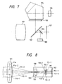
- Fig. 7 of the accompanying drawings is a schematic view of the optical system (optical apparatus) of a focus detecting apparatus using the conventional art image deviation system.
- the reference numeral 101 designates an objective lens (a photo-taking lens) for effecting photographing
- the reference numeral 102 denotes a half-transmitting main mirror
- the reference numeral 103 designates a focusing screen
- the reference numeral 104 denotes a pentagonal prism
- the reference numeral 105 designates an eyepiece
- the reference numeral 106 denotes a sub-mirror
- the reference numeral 107 designates film (a photosensitive surface)
- the reference numeral 108 denotes a focus detecting apparatus.
- a light beam from an object is transmitted through the objective lens 101, whereafter it is upwardly reflected by the main mirror 102 and forms an object image on the focusing screen 103.
- the object image formed on the focusing screen 103 is visually confirmed by a photographer or an observer through the eyepiece 105 via several times of reflection by the pentagonal prism 104.
- part of the light beam which has passed through the objective lens 101 to the main mirror 102 is transmitted through the transmitting portion of the main mirror 102, is downwardly reflected by the sub-mirror 106 and is guided to the focus detecting apparatus 108.
- Fig. 8 of the accompanying drawings is an illustration in which only the objective lens 101 and focus detecting apparatus 108 in Fig. 7 are taken out and developed to illustrate the principle of focus detection.
- the reference numeral 109 designates a field mask disposed near the predetermined focal plane of the objective lens 101, i.e., a plane conjugate with the film surface 107
- the reference numeral 110 denotes a field lens disposed also near the predetermined focal plane
- the reference numeral 111 designates a secondary imaging system comprising two lenses 111-1 and 111-2
- the reference numeral 112 denotes a photoelectrical changing element including two sensor arrays 112-1 and 112-2 disposed correspondingly to and rearwardly of the two lenses 111-1 and 111-2
- the reference numeral 113 designates an aperture having two opening portions 113-1 and 113-2 disposed correspondingly to the two lenses 111-1 and 111-2
- the reference numeral 114 denotes the exit pupil of the objective lens 101 including two divided areas 114-1 and 114-2.
- the field lens 110 has the function of imaging the opening portions 113-1 and 113-2 of the aperture 113 near the areas 114-1 and 114-2 in the exit pupil 114 of the objective lens 101, and light beams (flux) 115-1 and 115-2 transmitted through the areas 114-1 and 114-2 of the exit pupil 114 may form distributions of quantity of light regarding the object image on the two sensor arrays 112-1 and 112-2.
- the focus detecting apparatus shown in Fig. 8 is what is generally called a phase difference detection system (an image deviation system), and when the imaging point of the objective lens 101 is on the front side of the predetermined focal plane, i.e., on the objective lens 101 side, the distributions of quantity of light regarding the object images formed on the two sensor arrays 112-1 and 112-2 become close to each other, and when conversely, the imaging point of the objective lens 101 is on the rear side of the predetermined focal plane, i.e., on the side opposite to the objective lens 101, the distributions of quantity of light regarding the object images formed on the two sensor arrays 112-1 and 112-2 become far from each other.
- a phase difference detection system an image deviation system
- the amount of deviation of the distributions of quantity of light regarding the object images formed on the two sensor arrays 112-1 and 112-2 is in a certain functional relation with the defocus amount, i.e., the off-focus amount, of the objective lens 101 and therefore, by calculating the amount of deviation by suitable calculating means, the direction and amount of off-focus of the objective lens 101 are detected.
- a light beam necessary for focus detection is guided to the focus detecting apparatus 108 via the sub-mirror 106. Therefore, the range of an area in the photographing range in which focus detection is possible is restricted by the size (area) of the sub-mirror 106.
- the sub-mirror 106 has been particularly difficult to enlarge upwardly from its disposition relation with the main mirror 102 and accordingly, it has been impossible to enlarge the area in which focus detection is possible upwardly above the film 107, i.e., downwardly on the object side.
- the field lens In order that the field lens may not become large relative to the upwardly moved predetermined focal plane, the field lens can be upwardly moved in accordance with the predetermined focal plane, but if this is done, the field lens will intercept the photographing light beam and thus, during photographing, it is necessary to retract the field lens out of the phototaking light beam. To realize this, mechanical structure becomes very much complicated and costly and moreover, it becomes difficult to maintain the accuracy equal to that of the conventional art focus detecting apparatus.
- Some of conventional art focus detecting apparatuses have a plurality of focus detecting systems so as to enable focus detection to be accomplished in a plurality of areas, but the respective focus detection areas have been isolated from each other and focusing could not be effected on an object lying in the intermediate portion of each focus detection area.
- a focus detecting apparatus comprises:
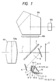
- Fig. 1 is a schematic view of the essential portions of Embodiment 1 of the present invention.
- Fig. 2 is an enlarged illustration of a portion of the focus detecting apparatus of Fig. 1.
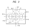
- Fig. 3 is an illustration showing the aperture and secondary imaging system of Fig. 1.
- Fig. 4 is an illustration showing the photoelectric conversion element of Fig. 1.
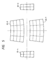
- Fig. 5 is an illustration showing the distortion of an image on the imaging plane of Fig. 1.
- Fig. 6 is an illustration showing the distortion of an image on the phototelectric conversion element of Fig. 1.
- Fig. 7 is a schematic view showing a camera having a focus detecting apparatus according to the conventional art.
- Fig. 8 is a schematic view showing the focus detecting apparatus according to the conventional art.
- Fig. 9 is an illustration showing the construction of a portion of an embodiment of the present invention.
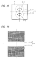
- Fig. 10 is an illustration showing the aperture and secondary imaging system in the embodiment of the present invention.
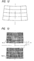
- Fig. 11 is an illustration showing a photoelectric conversion element in the embodiment of the present invention.
- Fig. 12 is an illustration showing the distortion of an image on the imaging plane of a reflecting mirror in the embodiment of the present invention.
- Fig. 13 is an illustration showing the distortion of an image on the photoelectric conversion element.
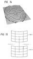
- Fig. 14 is an illustration showing the shape of the reflecting surface of a first reflecting mirror in the embodiment of the present invention.
- Fig. 15 is an illustration showing images on the photoelectric conversion element in the embodiment of the present invention.
- Fig. 16 is an illustration showing the shape of the reflecting surface of a second reflecting mirror in Embodiment 2 of the present invention.
- Fig. 17 is an illustration showing an image on a photoelectric conversion element in Embodiment 2 of the present invention.
- Fig. 18 is an illustration showing the shape of the reflecting surface of a first reflecting mirror in Embodiment 3 of the present invention.
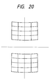
- Fig. 19 is an illustration showing the shape of the reflecting surface of a second reflecting mirror in Embodiment 3 of the present invention.
- Fig. 20 is an illustration showing an image on a photoelectric conversion element in Embodiment 3 of the present invention.
- Figs. 21A and 21B are illustrations showing the exit pupil of an objective lens and the entrance pupil of a focus detecting apparatus according to Embodiment 3 of the present invention.
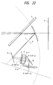
- Fig. 22 is an illustration showing the construction of Embodiment 4 of the present invention.
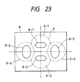
- Fig. 23 is an illustration showing an aperture and secondary imaging system in Embodiment 4 of the present invention.
- Fig. 24 is an illustration showing a photoelectric conversion element in Embodiment 4 of the present invention.
- Fig. 25 is an illustration showing the shape of the reflecting surface of a first reflecting mirror in Embodiment 4 of the present invention.
- Fig. 26 is an illustration showing the shape of the reflecting surface of a second reflecting mirror in Embodiment 4 of the present invention.
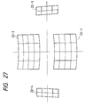
- Fig. 27 is an illustration showing an image on the photoelectric conversion element in Embodiment 4 of the present invention.
- Fig. 1 is a schematic view of the essential portions of Embodiment 1 in which the focus detecting apparatus of the present invention is applied to an optical apparatus such as a camera
- Fig. 2 is a schematic view of essential portions constituting the focus detecting apparatus of Fig. 1.
- the reference numeral 101 designates an objective lens
- the reference numeral 1 denotes the optical axis of the objective lens 101
- the reference numeral 2 designates a film (image pickup surface)
- the reference numeral 3 denotes a half-transmitting main mirror disposed on the optical axis 1 of the objective lens 101
- the reference numeral 103 designates a focusing screen on which an object image by the objective lens 101 is formed through the main mirror 3.
- the reference numeral 104 denotes a pentagonal prism
- the reference numeral 105 designates an eyepiece through which the object image on the focusing screen 103 is observed.
- the reference numeral 4 denotes a first reflecting mirror disposed obliquely relative to the optical axis 1 on the image plane side of the objective lens 101, and comprising a light condensing concave mirror or an elliptical surface mirror or the like.
- the reference numeral 5 designates a paraxial imaging plane by the first reflecting mirror 4 which is conjugate with the film 2 and on which the object image is formed.
- the reference numeral 6 denotes a second reflecting mirror
- the reference numeral 7 designates an infrared cut filter
- the reference numeral 8 denotes an aperture having four openings 8-1, 8-2, 8-3 and 8-4
- the reference numeral 9 designates a secondary imaging system having four lenses 9-1, 9-2, 9-3 and 9-4 disposed correspondingly to the four openings 8-1, 8-2, 8-3 and 8-4 in the aperture 8
- the reference numeral 10 denotes a third reflecting mirror
- the reference numeral 11 designates a photoelectrical changing element (light receiving means) having four area sensors 11-1, 11-2, 11-3 and 11-4.
- the first reflecting mirror 4, the second reflecting mirror 6 and the secondary imaging system 9 each constitute an element of optical means.
- three or more pairs of lens portions may be provided and the other elements may be constituted in conformity therewith.
- the first reflecting mirror 4 in the present embodiment has a light condensing curvature and is adapted to project the four openings 8-1, 8-2, 8-3 and 8-4 in the aperture 8 onto the vicinity of the exit pupil 101a of the objective lens 101.
- the first reflecting mirror 4 has metallic film such as aluminum or silver deposited by evaporation thereon so that only the necessary portion thereof may reflect light, and serves also as a field mask (regulating means) for limiting a range in which focus detection is effected.
- regulating means for limiting a range in which focus detection is effected.
- Each reflecting mirror has applied thereto regulating means such as applying a light absorbing paint or the like to an area thereof which does not function as a reflecting surface, or providing a light intercepting member in proximity thereto.
- Fig. 3 is a plan view of the aperture 8 of Fig. 1.
- the aperture 8 is of such a construction that laterally long two openings 8-1 and 8-2 are arranged in a direction of narrow opening width (a vertical direction in the phototaking range) and vertically long two openings 8-3 and 8-4 are arranged in the left to right direction (horizontal direction) in the photographing range.
- What are indicated by dotted lines in Fig. 3 are the lenses 9-1, 9-2, 9-3 and 9-4 of the secondary imaging system 9 which are disposed correspondingly to and rearwardly of the openings 8-1, 8-2, 8-3 and 8-4 in the aperture 8.
- the openings 8-3 and 8-4 in the aperture 8 are disposed more outside than the openings 8-1 and 8-2 so as to introduce the light in the area around the pupil of the objective lens 101.
- the so-called base line length during focus detection is made greater.
- the focus detecting system by the openings 8-3 and 8-4 in the aperture 8 can enhance focus detection accuracy for an objective lens of bright F-number.
- the openings 8-1, 8-2 and openings 8-3, 8-4 in the aperture 8 differ in shape from each other, and the directions of separation thereof are orthogonal to each other and the distances of separation thereof differ from each other.
- Fig. 4 is a plan view of the photoelectric conversion element 11, and as shown in this figure, the four area sensors 11-1, 11-2, 11-3 and 11-4 shown in Fig. 1 are four area sensors 11-1, 11-2, 11-3 and 11-4 in which a plurality of pixels are two-dimensionally arranged and which are arranged.
- the light beam from the object image formed on the paraxial imaging plane 5 is reflected by the second reflecting mirror 6 and changes its direction again, whereafter it is condensed by the lenses 9-1, 9-2, 9-3 and 9-4 of the secondary imaging system 9 via the infrared cut filter 7 and the four openings 8-1, 8-2, 8-3 and 8-4 in the aperture 8, and arrives at the area sensors 11-1, 11-2, 11-3 and 11-4 of the photoelectric conversion element 11 via the third reflecting mirror 10.
- the light beams 12-1, 12-2, 12-3 and 12-4 in Fig. 2 indicate light beams imaged at the center of the film 2, but light beams imaged at other positions arrive at the photoelectrical changing element 11 via a similar route and as a whole, four distributions of quantity of light regarding the object image are formed on the area sensors 11-1, 11-2, 11-3 and 11-4 of the photoelectrical changing element 11 corresponding to predetermined two-dimensional areas on the film (in the photographing range) 2.
- the first reflecting mirror 4 is constructed of a part of a curved surface formed by a quadratic curve being rotated about an axis, and particularly a spheroidal surface is suitably used.
- the surface shape of the first reflecting mirror 4 comprises a part of a spheroidal surface formed by an ellipse 21 having a point 20 as its vertex being rotated about an axis 22, and the focus thereof is set near the central image position 23 on the aperture 8 by the second reflecting mirror 6 and near a point (not shown) on the extension of an optical axis 24 after the transmission through the main mirror 3.
- the exit pupil position of the objective lens 101 and the entrance position of the secondary imaging system 9 may be substantially imaged in such a manner that the point on the extension of the optical axis 24 is near the exit pupil position of the objective lens 101 (when various objective lenses are interchangeably used, their average exit pupil position).
- the first reflecting mirror 4 is adapted to function as an ideal field lens.
- what is optically used as the first reflecting mirror 4 is an area which does not include the rotational axis and vertex of the spheroidal surface.
- the entrance side surface (first surface) 9a of the secondary imaging system 9 is made into a concave surface shape to thereby provide such a lens construction that light entering the secondary imaging system 9 is not forcibly refracted, and good and uniform imaging performance is achieved over the wide range of the two-dimensional area on the photoelectrical changing element 11.
- the relative positional relation in the direction of separation i.e., the vertical direction of the two area sensors 11-1 and 11-2 shown in Fig. 4 is calculated at positions comprising any plurality of elements of the area sensors 11-1 and 11-2, or the relative positional relation in the horizontal direction of the two area sensors 11-3 and 11-4 is calculated at the positions of the area sensors 11-3 and 11-4, whereby the focus state of the objective lens 101 is two-dimensionally detected in any area in the phototaking range.
- the first reflecting mirror 4 is retracted out of the photographing optical path like the main mirror 3, during phototaking.
- the first reflecting mirror 4 has convergent power which projects the four openings 8-1, 8-2, 8-3 and 8-4 in the aperture 8 near the exit pupil 101a of the objective lens 101, and is provided obliquely with respect to the optical axis 1 and therefore, asymmetrical great distortion is created on the imaging plane 5 thereof.
- Fig. 12 is a plan view showing how distortedly rectangular checked figures are imaged on the imaging plane 5 in Fig. 2 by the first reflecting mirror 4 in the present embodiment when the rectangular checked figures are imaged on the film 2 by the objective lens 101, and the upper portion of Fig. 5 is the main mirror 3 side of Fig. 2.
- design is made such that the angle formed by the normal at the point of intersection with the optical axis 24 of the first reflecting mirror 4 and the optical axis 24 is made as small as possible and the reflected light beam is reflected in a direction substantially along the main mirror 3, i.e., as forwardly as possible. Accordingly, the angle formed by the ray of light incident along the optical axis and the reflected ray of light thereof is an acute angle.
- the second reflecting mirror 6 is provided to direct the forwardly reflected light beam to the secondary imaging system 9.
- the figures rectangularly formed on the film 2 are imaged in a sector narrow at its upper portion and wide at its lower portion on the imaging plane 5 by the first reflecting mirror 4. Thus, if they are reimaged in this state on the photoelectrical changing element 11 by the secondary imaging system 9, distorted images will be formed also on the photoelectrical changing element 11.
- Fig. 5 is an illustration showing distortion of an image on a sensor.
- Fig. 6 is a plan view of the photoelectrical changing element 11 showing that state, and on the area sensors 11-1, 11-2, 11-3 and 11-4, rectangles are formed as distorted images as indicated by images 13-1, 13-2, 13-3 and 13-4.
- the area sensors are constructed with rectangular pixels regularly arranged in vertical and horizontal directions as shown as the area sensors 11-1, 11-2, 11-3 and 11-4 of Fig. 6, and their configurations are usually rectangular.
- the fact that the distorted images 13-1, 13-2, 13-3 and 13-4 as shown in Fig. 6 are formed means that the images of the four rectangular area sensors 11-1, 11-2, 11-3 and 11-4 reversely projected onto the film 2 become conversely distorted and the field of view for effecting focus detection is inclined in the marginal portion thereof.
- the output from the photoelectrical changing element can be calculated and corrected by a method similar to that disclosed, for example, in Japanese Laid-Open Patent Application No. 62-173412 and therefore, if there is no deviation between two object images in a direction perpendicular to the low direction (correlative direction) of the area sensors 11, focus detection can be effected well.
- the four individual object images formed on the four area sensors 11-1, 11-2, 11-3 and 11-4 exhibit great distortion, but the difference of the distortion in the direction which is perpendicular to the row direction (correlative direction) of the area sensors 11 is sufficiently small.
- a light intercepting member for example, a mask of aluminum or the like, curved correspondingly to the difference in distortion along each sensor array can be provided on the light receiving surface of each sensor, as disclosed in Japanese Laid-Open Patent Application No. 61-15112, to thereby improve accuracy.
- the vertex positions (the lens surface vertex positions) of the exit side surfaces of the two lenses 9-1 and 9-2 of the secondary imaging lens 9 along the optical axis can be set so as to differ from each other or the whole of the secondary imaging lens 9 can be set obliquely with respect to the optical axis and the imaging magnifications of the two lenses 9-1 and 9-2 can be varied.
- the photoelectrical changing element 11 being inclined instead of being provided perpendicularly to the optical axis, the adjustment of the magnifications and distortions of the two object images can be effected.
- the above-described embodiment is such that as shown in Fig. 4, four distributions of quantity of light regarding the object images are formed in the vertical direction and the horizontal direction on the photoelectrical changing element 11 and the deviations in the vertical direction and in the horizontal direction are detected.
- focus detection is possible both for an object like a horizontal line having light and shade in a vertical direction, and for an object like a vertical line having light and shade in a horizontal direction.
- the field areas corresponding to the area sensors 11-3 and 11-4 for detecting the phase difference between the object images in the horizontal direction are set small relative to the field areas corresponding to the area sensors 11-1 and 11-2 for detecting the phase difference between the object images in the vertical direction. This is for the following reason.
- the distortions of the rectangular images 13-1 and 13-2 of the Fig. 6 or the difference therebetween and the distortions of the rectangular images 13-3 and 13-4 or the difference therebetween small at a time, but it is not always easy to make these compatible because the directions in which the difference between the two images particularly poses a problem are orthogonal to each other.
- the light beams forming the two sets of object images are reflected in an area common in the first reflecting mirror and the second reflecting mirror and therefore, it is also difficult to cope with the problem by contriving the shapes of these reflecting mirrors. In such a situation, it is very effective to set the direction in which the phase difference of one of the two sets of object images is detected short.
- the photoelectrical changing element 11 can avoid becoming extremely bulky and it becomes possible to dispose the focus detecting apparatus easily even in a limited space within a camera. Further, to effect focus detection in any two-dimensional area, an enormous calculating process is necessary as compared with the conventional art focus detecting apparatus, and it is advantageous in effecting quick focus detection to make the pixels of the sensors necessary minimum.
- the reflecting mirror 4 is especially contrived.
- the first reflecting mirror 4 is made into a surface, in which a rotation symmetry axis is absent.
- a general expression representing the surface shape of the first reflecting mirror 4 used in the present embodiment is shown in the following expression (1), and the specific expressions of Pi (y, z) in expression (1) are shown in Table 1 below.
- the first term in expression (1) represents a spherical surface of a radius R, and the second term is what is called Zernike's polynominal.
- each coefficient Ci in expression (1) in the present embodiment is shown in Table 2 below.
- Each coefficient in Table 2 is for the coordinates system 14 attached to the first reflecting mirror 4 of Fig. 9.
- Fig. 14 is a bird's-eyeview when the shape of the portion of the surface shape of the first reflecting mirror in the present embodiment except the spherical surface of the first term represented by expression (1) is seen from the positive direction of the x coordinates axis of the coordinates system 14 of Fig. 9.
- the surface shape of the first reflecting mirror 4 has symmetry with respect to xy plane which is attributable to the symmetry of the focus detecting system shown in Fig. 9, but lacks such a rotational axis that will become rotation-symmetrical.
- Fig. 15 shows rectangular images 13-1 and 13-2 on the photoelectric conversion element 11 corresponding to Fig. 13 when the surface shape of the present embodiment is applied to the first reflecting mirror 4. It will be seen that the inclination with respect to the row direction (vertical direction) in which the phase difference between the area sensors on the photoelectrical changing element 11 is detected is corrected. Distortion remains in a direction orthogonal to this direction, but it will hardly pose a problem in effecting focus detection because the widthwise direction (horizontal direction) of the sensor arrays affected by the distortion is sufficiently narrow.
- the magnification of an image formed by a light beam reflected by the upper portion (the positive direction of the y-axis) of the reflecting mirror 4 becomes small and conversely, the magnification of an image formed by a light beam reflected by the lower portion (the negative direction of the y-axis) of the reflecting mirror 4 becomes great.
- the reflecting mirror 4 in the present embodiment in its upper portion assumes a convex shape relative to the central portion, i.e., such a surface shape that has divergent power, to deflect the rays of light more outside
- a concave shape relative to the central portion i.e., such a surface shape that has convergent power
- the great distortion as shown in Fig. 13 is corrected by using the reflecting mirror of the present embodiment, but there is the possibility of sufficiently small distortion relative to the width of the sensor array remaining. It is possible to correct such minute distortion that cannot be neglected when highly accurate focus detection is effected by forming a light intercepting member, for example, a mask of aluminum or the like, curved in conformity with the distortion remaining on the sensor array, on the light receiving surface of each sensor, as disclosed in Japanese Laid-Open Patent Application No. 61-15112. During the correction, the distortion of each of the images formed on the two area sensors may be directly corrected, or the difference between the distortions of the images formed on the two area sensors may be corrected.
- the distortion in the row direction of the sensors which is the direction in which the phase difference between two images is detected can be corrected by calculation-processing the output from the photoelectric conversion element by the technique disclosed in Japanese Laid-Open Patent Application No. 62-173412.
- the vertex positions of the exit side surfaces of the two lenses 9-1 and 9-2 of the secondary imaging system 9 along the optical axis can be set so as to differ from each other, on the whole of the secondary imaging system 9 can be set obliquely with respect to the optical axis and the imaging magnifications of the two lenses 9-1 and 9-2 can be varied.
- the adjustment of the magnifications and distortion of the two images can also be effected by not providing the photoelectrical changing element 11 perpendicularly to the optical axis, but inclining it.
- the present embodiment is one in which a reflecting surface free of axis symmetry is applied to the first reflecting mirror 4 in Fig. 9, but the object of the present invention can also be achieved by using a surface having a similar characteristic in the second reflecting mirror 6.
- Table 3 shows the specific numerical values of another embodiment of the present invention in which the first reflecting mirror 4 in Fig. 9 is made spherical and a surface free of axis symmetry is used in the second reflecting mirror 6 by the coefficients of Zernike's polynominal as in the previous embodiment, and Fig. 16 shows a bird's-eye view when the shape of Embodiment 3 represented by the same table is seen from the position direction of the x coordinates axis of the coordinates system 15 of Fig. 9.
- Fig. 16 unlike Fig. 14, includes the spherical term of expression (1).
- Fig. 17 shows the imaged state on the photoelectrical changing element 11 when the shape represented by Table 3 is used as the surface of the second reflecting mirror 6, and as in Fig. 15, the correction of the distortion of the images is effected.
- the reflecting mirror 6 of Embodiment 3 in its upper portion (the positive portion of the y-axis), assumes a concave shape relative to the central portion, i.e., such a surface shape that the convergent power, so as to deflect the rays of light more inside, and in its lower portion, assumes a convex shape relative to the central portion, i.e., such a surface shape that has divergent power, so as to deflect the rays of light more outside, in order to eliminate or alleviate the distortion of the images.
- the reflecting mirror of the present embodiment has a characteristic converse in the vertical direction, and this is because the light beam incident on the marginal portion of the first reflecting mirror 4 is indined in a direction diverging relative to the optical axis 1, whereas the light beam incident on the marginal portion of the second reflecting mirror 6 is conversely inclined in a direction converging from each point on the imaging plane 5 toward the openings 8-1 and 8-2 in the aperture 8.
- a focus detecting system of the phase difference type it is necessary to prevent a light beam to be taken in by the focus detecting system from being intercepted by the pupil of an objective lens.
- the focus detecting apparatus of the present invention is used only for bright limited objective lenses, it will pose no great problem, but yet when as in a single-lens reflex camera, it is applied to interchangeable lenses having various pupil positions and various degrees of brightness, it is necessary to adopt a construction taking the pupil projection relation between the objective lens and the focus detecting system into account.
- the pupil projection of the two in the present invention is effected chiefly by the power of the first reflecting mirror 4, but it is also greatly affected by the surface shape of the second reflecting mirror 6. Accordingly, when the pupil condition of the objective lens is severe, it is necessary to optimize the projection of the pupil at the same time when the correction of the distortion of the images shown in Embodiments 2 and 3 is effected.
- Embodiment 4 of the present invention which has realized this will herein after be described with reference to Figs. 18, 19, 20, 21A and 21B.
- Embodiment 4 is one in which a reflecting surface having no rotation symmetry axis is used in each of the first reflecting mirror 4 and the second reflecting mirror 6 and the distortion of the images on the photoelectrical changing element 11 is corrected and also the projection relation between the exit pupil 101a of the objective lens 101 and the entrance pupil (aperture 8) of the focus detecting apparatus is well optimized.
- Figs. 18 and 19 are bird's-eye views showing the surface shapes of the first reflecting mirror 4 and the second reflecting mirror 6, and in these figures, the coordinates axes and the directions in which the surfaces are seen are the same as those in Figs. 14 and 16. Also, Tables 4 and 5 show Zernike's coefficients representing the surface shapes of the respective reflecting mirrors.
- Fig. 20 shows the shapes of rectangular images on the photoelectrical changing element 11 when these reflecting mirrors are used, and as in Embodiments 2 and 3, the distortion of the images is corrected.
- the surface shape of the first reflecting mirror 4 of Embodiment 4 shown in Fig. 18, like the first reflecting mirror of Embodiment 2, is such that in the upper portion (the positive direction of the y-axis) of the reflecting mirror, it has a convex shape relative to the central portion, i.e., divergent power, in order to deflect the rays of light more outside, and conversely in the lower portion (the negative direction of the y-axis) on which the light beam is incident and which corresponds to an area in which the magnification becomes greater, it has a concave shape relative to the central portion, i.e., convergent power, in order to deflect the rays of light more inside, and the surface shape of the second reflecting mirror 6 of Embodiment 4 shown in Fig.
- the 19 is designed to have more convergent power in the upper portion (the positive direction of the y-axis) of the reflecting mirror, and more divergent power in the lower portion (the negative direction of the y-axis) of the reflecting mirror.
- each reflecting mirror in Embodiment 4 the optimization of the projection of the pupil is effected at the same time and therefore, the power distributions of the respective reflecting mirrors somewhat differ from each other, but the reflecting mirrors in the present embodiment have characteristics similar to those in the previous embodiments and achieve the object of the present invention.
- Figs. 21A and 21B shows the shapes 16 and 17 of the exit pupil of the objective lens as it is seen from the two upper and lower apexes of that rectangle in the rectangular focus detection range defined on the film 2 which is severest in the condition of pupil projection, and the images 18-1, 18-2 and 19-1, 19-2 of the openings 8-1 and 8-2 in the aperture 8 of the focus detecting apparatus projected onto the same surface via the first reflecting mirror 4 and second reflecting mirror 6 of Embodiment 4.
- the projected images 18-1, 18-2 and 19-1, 19-2 of the openings 8-1 and 8-2 in the aperture 8 are present in the exit pupils 16 and 17 of the objective lens wherein aperture eclipse has occurred, and the light beam to be directed to the focus detecting system is not intercepted by the pupil of the objective lens.
- the above-described embodiments are ones which form two distributions of quantity of light vertically on the photoelectrical changing element 11 as shown in Fig. 11 and detect the vertical deviation therebetween.
- focus detection is possible only for an object such as a lateral line having light and shade in a vertical direction, and focus detection is impossible for an object such as a vertical line having light and shade in a horizontal direction.
- Embodiment 5 is an improvement in this point, and the construction thereof is shown in Fig. 22.
- the difference of this embodiment from the embodiment of Fig. 9 is that two lenses 9-3 and 9-4 are disposed in the secondary imaging system 9 comprising two lenses 9-1 and 9-2 in a direction orthogonal thereto and provision is made of openings 8-3 and 8-4 in the aperture 8 corresponding thereto and area sensors 11-3 and 11-4 on the photoelectric conversion element 11.
- Fig. 23 shows the shapes of the openings in the aperture 8 in Embodiment 5.
- the reference numerals 8-3 and 8-4 designate the newly added openings
- the reference numerals 9-3 and 9-4 denote two lenses constituting the second imaging system 9 which are disposed correspondingly to and rearwardly of the newly added openings.
- the openings 8-3 and 8-4 in the aperture 8 of Fig. 23 are disposed more outside as compared with the openings 8-1 and 8-2, so as to introduce the light in the area around the pupil of the objective lens.
- the so-called base line length during focus detection can be made greater and the focus detecting system by the newly added openings 8-3 and 8-4 in the aperture 8 in Embodiment 5 can enhance focus detection accuracy for bright objective lenses.
- the positions from the center at which the openings 8-3 and 8-4 are disposed are the same as those of the openings 8-1 and 8-2 and focus detection is always possible for an object equal in focus detection accuracy but having a distribution of light and shade only in one of the vertical and horizontal directions, irrespective of the brightness of the objective lens.
- Fig. 24 shows area sensors 11-3 and 11-4 on the photoelectrical changing element 11 on which distributions of quantity of light are formed by secondary imaging lenses 9-3 and 9-4.
- Table 6 and Fig. 25 show Zernike's coefficients representing the surface shape of the first reflecting mirror used in Embodiment 5 and a bird's-eye view, respectively
- Table 7 and Fig. 26 show Zernike's coefficients representing the surface shape of the second reflecting mirror used in Embodiment 5 and a bird's-eye view, respectively. From Figs. 25 and 26, it is seen that both of the reflecting mirrors have surface shapes having characteristics similar to those of the hitherto described embodiments.
- Fig. 27 shows an imaged state on the photoelectrical changing element 11 similar to that shown in Figs. 15 and 17 when these reflecting mirrors are used, and rectangular images 22-1 and 22-2 formed in the vertical direction and rectangular images 22-3 and 22-4 formed in the horizontal direction have their distortion substantially corrected in a direction in which the phase difference is detected.
- the field areas corresponding to the area sensors 11-3 and 11-4 for detecting the phase difference between the images in the horizontal direction are set small relative to the field areas corresponding to the area sensors 11-1 and 11-2 for detecting the phase difference between the images in the vertical direction. This is for the following reason.
- the distortion correction for the rectangular images 22-1 and 22-2 in Fig. 27 and the distortion correction for the rectangular images 22-3 and 22-4 be effected at a time, but since the directions in which these should be corrected are orthogonal to each other, it is not always easy to realize sufficient correction. It also makes simultaneous correction difficult that the light beams forming those images are reflected in a common area in the first reflecting mirror and the second reflecting mirror. In order to solve such a problem, it is very effective to set the direction in which the phase difference of one of the two sets of object images is detected short.
- the photoelectrical changing element 11 can avoid becoming extremely large and it becomes possible for the focus detecting apparatus to be easily disposed even in a limited space in a camera. Further, to effect focus detection in any two-dimensional area, an enormous calculating process is necessary as compared with the conventional art focus detecting apparatus, and it is advantageous in effecting quick focus detection to make the pixels of the sensors necessary minimum.
- a reflecting surface shape free of axis symmetry is used in the first or second reflecting mirror
- a similar reflecting surface shape may be applied to the third reflecting mirror 10 of Fig. 9.
- the third reflecting mirror is for disposing the focus detecting apparatus in a limited space in the bottom portion of a camera, but generally a reflecting surface free of axis symmetry is used for a reflecting surface provided between the first reflecting mirror and the photoelectrical changing element as required, whereby the object of the present invention is achieved.
- the second reflecting mirror 6 is designed to be retracted out of the photographing optical path during photographing with the main mirror 3 and the first reflecting mirror 4, but if it can be disposed in a camera, the second reflecting mirror may be provided at a lower position avoiding the photographing optical path and may be a fixed reflecting mirror which is not moved even during photographing. By doing so, mechanical structure can be simplified and also, the occurrence of an error resulting from the movement of the second reflecting mirror can be eliminated and thus, more highly accurate focus detection becomes possible.
- the present invention is not restricted thereto, but is also effective for a focus detecting apparatus of other type effecting secondary imaging, for example, an apparatus for detecting the focus state from the sharpness of an object image.
- the present invention is suitably used when an area in which focus detection is possible is to be enlarged to a two-dimensional continuous area, but even if the present invention is applied to a conventional art focus detecting apparatus using a one-dimensional line sensor, the focus detecting position can be set more marginally.
- a focus detecting apparatus in which each element of optical means for focus detection provided on the image plane side of an objective lens (a photo-taking lens) is appropriately set, whereby in any area or/and a plurality of areas in a vertical direction in a photographing field, an area in which focus detection is possible can be enlarged particularly to the upper portion in a photographing range and focus detection can be effected highly accurately also at any point in a continuous two-dimensional area, and an optical apparatus using the same.
- focus detection accuracy is maintained and yet the area in which focus detection is possible can be markedly enlarged. Also, focus detection is extended to a continuous two-dimensional area and it is easily possible to focus on an object at any desired position, and in the two-dimensional area wherein the degree of freedom of the setting of composition when photographing or observation is done increases, focus detection becomes possible irrespective of the direction of the density distribution of the object and thus, the frequency with which focus detection becomes impossible decreases markedly.
- Focus detection is made possible in the two-dimensional area and yet optimum focus detection accuracy can be selected in conformity with the brightness of the objective lens and therefore, even for a large-aperture lens of a shallow depth, focusing becomes possible with sufficient accuracy.
Landscapes
- Physics & Mathematics (AREA)
- General Physics & Mathematics (AREA)
- Optics & Photonics (AREA)
- Focusing (AREA)
- Automatic Focus Adjustment (AREA)
Applications Claiming Priority (9)
| Application Number | Priority Date | Filing Date | Title |
|---|---|---|---|
| JP35410595 | 1995-12-28 | ||
| JP35410495A JP3368129B2 (ja) | 1995-12-28 | 1995-12-28 | 焦点検出装置及びそれを用いた光学機器 |
| JP35410395 | 1995-12-28 | ||
| JP35410395A JP3363683B2 (ja) | 1995-12-28 | 1995-12-28 | 焦点検出装置及びそれを用いた光学機器 |
| JP354103/95 | 1995-12-28 | ||
| JP35410595A JPH09184967A (ja) | 1995-12-28 | 1995-12-28 | 焦点検出装置及びそれを用いた光学機器 |
| JP354105/95 | 1995-12-28 | ||
| JP354104/95 | 1995-12-28 | ||
| JP35410495 | 1995-12-28 |
Publications (3)
| Publication Number | Publication Date |
|---|---|
| EP0782026A2 true EP0782026A2 (fr) | 1997-07-02 |
| EP0782026A3 EP0782026A3 (fr) | 1997-10-08 |
| EP0782026B1 EP0782026B1 (fr) | 2003-07-09 |
Family
ID=27341471
Family Applications (1)
| Application Number | Title | Priority Date | Filing Date |
|---|---|---|---|
| EP96309498A Expired - Lifetime EP0782026B1 (fr) | 1995-12-28 | 1996-12-24 | Dispositif de détection de mise au point |
Country Status (3)
| Country | Link |
|---|---|
| US (1) | US5839001A (fr) |
| EP (1) | EP0782026B1 (fr) |
| DE (1) | DE69629000T2 (fr) |
Cited By (3)
| Publication number | Priority date | Publication date | Assignee | Title |
|---|---|---|---|---|
| EP0834757A3 (fr) * | 1996-09-27 | 1999-04-28 | Canon Kabushiki Kaisha | Détecteur de l'état de focalisation |
| DE19948639B4 (de) * | 1998-10-09 | 2005-03-10 | Pentax Corp | Kamera mit einer Einrichtung zum Nachweis der Scharfeinstellung |
| EP2180370A1 (fr) * | 2008-10-24 | 2010-04-28 | Samsung Electronics Co., Ltd. | Miroir secondaire et apareil pour formation d'images comprenant le même |
Families Citing this family (15)
| Publication number | Priority date | Publication date | Assignee | Title |
|---|---|---|---|---|
| JPH10206723A (ja) * | 1997-01-24 | 1998-08-07 | Nikon Corp | 焦点検出装置 |
| JP3647223B2 (ja) * | 1997-09-29 | 2005-05-11 | キヤノン株式会社 | 焦点検出装置および光学機器 |
| JP4018218B2 (ja) | 1997-12-25 | 2007-12-05 | キヤノン株式会社 | 光学装置及び測距点選択方法 |
| JPH11338041A (ja) * | 1998-05-26 | 1999-12-10 | Canon Inc | 光学装置及び視線検出機能付きカメラ |
| US6175692B1 (en) | 1998-05-26 | 2001-01-16 | Canon Kabushiki Kaisha | Focus detecting device, distance measuring device, and optical apparatus for adjusting focus |
| JP2000171695A (ja) | 1998-12-09 | 2000-06-23 | Asahi Optical Co Ltd | 焦点検出装置 |
| JP5002086B2 (ja) | 1999-10-28 | 2012-08-15 | キヤノン株式会社 | 焦点検出装置と撮像装置 |
| US6577434B2 (en) | 2000-01-14 | 2003-06-10 | Minolta Co., Ltd. | Variable focal position spatial modulation device |
| JP4560173B2 (ja) | 2000-05-30 | 2010-10-13 | キヤノン株式会社 | 焦点検出装置 |
| JP4011829B2 (ja) | 2000-06-14 | 2007-11-21 | キヤノン株式会社 | 撮像装置及びその制御方法 |
| JP3609988B2 (ja) | 2000-06-21 | 2005-01-12 | ペンタックス株式会社 | 焦点検出装置 |
| JP4532968B2 (ja) * | 2004-04-13 | 2010-08-25 | キヤノン株式会社 | 焦点検出装置 |
| JP2005308805A (ja) * | 2004-04-16 | 2005-11-04 | Olympus Corp | 焦点検出装置及び光学機器 |
| JP2006003427A (ja) * | 2004-06-15 | 2006-01-05 | Canon Inc | 焦点検出装置及び撮影装置 |
| JP2007010951A (ja) * | 2005-06-30 | 2007-01-18 | Canon Inc | 焦点検出装置及び撮像装置 |
Citations (2)
| Publication number | Priority date | Publication date | Assignee | Title |
|---|---|---|---|---|
| JPS6115112A (ja) | 1984-07-02 | 1986-01-23 | Canon Inc | 焦点検出装置 |
| JPS62173412A (ja) | 1986-01-27 | 1987-07-30 | Canon Inc | 焦点検出装置 |
Family Cites Families (6)
| Publication number | Priority date | Publication date | Assignee | Title |
|---|---|---|---|---|
| DE2609877A1 (de) * | 1976-03-10 | 1977-09-15 | Leitz Ernst Gmbh | Optische anordnung zur benutzung von sensoren |
| NL187413C (nl) * | 1978-03-16 | 1991-09-16 | Philips Nv | Registratiedragerlichaam, ingeschreven registratiedrager, werkwijze voor het inschrijven van het registratiedragerlichaam en inrichting voor het uitvoeren van de werkwijze en voor het uitlezen van een ingeschreven registratiedrager. |
| US4555169A (en) * | 1983-09-13 | 1985-11-26 | Canon Kabushiki Kaisha | Focus detecting device for a camera |
| JP2757396B2 (ja) * | 1988-11-25 | 1998-05-25 | 株式会社ニコン | カメラ |
| US5189460A (en) * | 1990-01-30 | 1993-02-23 | Canon Kabushiki Kaisha | Camera detecting luminance from a plurality of areas |
| JPH0498236A (ja) * | 1990-08-17 | 1992-03-30 | Olympus Optical Co Ltd | カメラ |
-
1996
- 1996-12-23 US US08/777,952 patent/US5839001A/en not_active Expired - Lifetime
- 1996-12-24 EP EP96309498A patent/EP0782026B1/fr not_active Expired - Lifetime
- 1996-12-24 DE DE69629000T patent/DE69629000T2/de not_active Expired - Lifetime
Patent Citations (2)
| Publication number | Priority date | Publication date | Assignee | Title |
|---|---|---|---|---|
| JPS6115112A (ja) | 1984-07-02 | 1986-01-23 | Canon Inc | 焦点検出装置 |
| JPS62173412A (ja) | 1986-01-27 | 1987-07-30 | Canon Inc | 焦点検出装置 |
Cited By (5)
| Publication number | Priority date | Publication date | Assignee | Title |
|---|---|---|---|---|
| EP0834757A3 (fr) * | 1996-09-27 | 1999-04-28 | Canon Kabushiki Kaisha | Détecteur de l'état de focalisation |
| US6577344B2 (en) | 1996-09-27 | 2003-06-10 | Canon Kabushiki Kaisha | Focus state detection apparatus with image sensing device controls |
| DE19948639B4 (de) * | 1998-10-09 | 2005-03-10 | Pentax Corp | Kamera mit einer Einrichtung zum Nachweis der Scharfeinstellung |
| EP2180370A1 (fr) * | 2008-10-24 | 2010-04-28 | Samsung Electronics Co., Ltd. | Miroir secondaire et apareil pour formation d'images comprenant le même |
| US8135272B2 (en) | 2008-10-24 | 2012-03-13 | Samsung Electronics Co., Ltd | Sub mirror and image pick-up apparatus having the same |
Also Published As
| Publication number | Publication date |
|---|---|
| US5839001A (en) | 1998-11-17 |
| DE69629000D1 (de) | 2003-08-14 |
| EP0782026B1 (fr) | 2003-07-09 |
| DE69629000T2 (de) | 2004-05-27 |
| EP0782026A3 (fr) | 1997-10-08 |
Similar Documents
| Publication | Publication Date | Title |
|---|---|---|
| EP0782026B1 (fr) | Dispositif de détection de mise au point | |
| US5005041A (en) | Focus detecting apparatus having a plurality of focus detecting areas | |
| US5864721A (en) | Focus detecting apparatus | |
| US6112029A (en) | Camera, exchangeable lens, and camera system | |
| US4855777A (en) | Apparatus for detecting the focus adjusted state of an objective lens | |
| US5771413A (en) | Focus detecting apparatus | |
| US5530236A (en) | Focus detecting apparatus with particular arrangement of light receiving portions | |
| US6813442B2 (en) | Autofocus system and camera system | |
| JPS63118112A (ja) | 焦点検出装置 | |
| JP3363683B2 (ja) | 焦点検出装置及びそれを用いた光学機器 | |
| US6643460B2 (en) | Camera and focal point detection apparatus | |
| US5805941A (en) | Camera having focus detecting optical system | |
| US5822627A (en) | Focus state detection device | |
| EP0878726B1 (fr) | Dispositif de détection de mise au point | |
| US6272291B2 (en) | Focus detecting device | |
| JP3890134B2 (ja) | 対物レンズ、撮像装置及びこれらを有した撮影システム | |
| JP3368129B2 (ja) | 焦点検出装置及びそれを用いた光学機器 | |
| JP2000171695A (ja) | 焦点検出装置 | |
| JP2001343580A (ja) | 焦点検出装置 | |
| US5289226A (en) | Focus detecting device including a diffusion surface disposed on a predetermined image surface | |
| US4428653A (en) | Mirror reflex camera with an electronic range finder | |
| US5565956A (en) | Focus detecting camera | |
| JP2701512B2 (ja) | 反射系を有した撮像装置 | |
| JP3912891B2 (ja) | 焦点検出装置及びそれを用いた光学機器 | |
| JP3696989B2 (ja) | 焦点検出装置とこれを用いたカメラ |
Legal Events
| Date | Code | Title | Description |
|---|---|---|---|
| PUAI | Public reference made under article 153(3) epc to a published international application that has entered the european phase |
Free format text: ORIGINAL CODE: 0009012 |
|
| AK | Designated contracting states |
Kind code of ref document: A2 Designated state(s): DE FR GB |
|
| PUAL | Search report despatched |
Free format text: ORIGINAL CODE: 0009013 |
|
| AK | Designated contracting states |
Kind code of ref document: A3 Designated state(s): DE FR GB |
|
| 17P | Request for examination filed |
Effective date: 19980218 |
|
| 17Q | First examination report despatched |
Effective date: 20000724 |
|
| GRAH | Despatch of communication of intention to grant a patent |
Free format text: ORIGINAL CODE: EPIDOS IGRA |
|
| GRAH | Despatch of communication of intention to grant a patent |
Free format text: ORIGINAL CODE: EPIDOS IGRA |
|
| GRAA | (expected) grant |
Free format text: ORIGINAL CODE: 0009210 |
|
| AK | Designated contracting states |
Designated state(s): DE FR GB |
|
| REG | Reference to a national code |
Ref country code: GB Ref legal event code: FG4D |
|
| REF | Corresponds to: |
Ref document number: 69629000 Country of ref document: DE Date of ref document: 20030814 Kind code of ref document: P |
|
| ET | Fr: translation filed | ||
| PLBE | No opposition filed within time limit |
Free format text: ORIGINAL CODE: 0009261 |
|
| STAA | Information on the status of an ep patent application or granted ep patent |
Free format text: STATUS: NO OPPOSITION FILED WITHIN TIME LIMIT |
|
| 26N | No opposition filed |
Effective date: 20040414 |
|
| PGFP | Annual fee paid to national office [announced via postgrant information from national office to epo] |
Ref country code: GB Payment date: 20141222 Year of fee payment: 19 Ref country code: DE Payment date: 20141231 Year of fee payment: 19 |
|
| PGFP | Annual fee paid to national office [announced via postgrant information from national office to epo] |
Ref country code: FR Payment date: 20141223 Year of fee payment: 19 |
|
| REG | Reference to a national code |
Ref country code: DE Ref legal event code: R119 Ref document number: 69629000 Country of ref document: DE |
|
| GBPC | Gb: european patent ceased through non-payment of renewal fee |
Effective date: 20151224 |
|
| REG | Reference to a national code |
Ref country code: FR Ref legal event code: ST Effective date: 20160831 |
|
| PG25 | Lapsed in a contracting state [announced via postgrant information from national office to epo] |
Ref country code: GB Free format text: LAPSE BECAUSE OF NON-PAYMENT OF DUE FEES Effective date: 20151224 Ref country code: DE Free format text: LAPSE BECAUSE OF NON-PAYMENT OF DUE FEES Effective date: 20160701 |
|
| PG25 | Lapsed in a contracting state [announced via postgrant information from national office to epo] |
Ref country code: FR Free format text: LAPSE BECAUSE OF NON-PAYMENT OF DUE FEES Effective date: 20151231 |