EP0782132A1 - Verfahren zur Herstellung eines magnetischen Aufzeichnungsträgers - Google Patents
Verfahren zur Herstellung eines magnetischen Aufzeichnungsträgers Download PDFInfo
- Publication number
- EP0782132A1 EP0782132A1 EP96120900A EP96120900A EP0782132A1 EP 0782132 A1 EP0782132 A1 EP 0782132A1 EP 96120900 A EP96120900 A EP 96120900A EP 96120900 A EP96120900 A EP 96120900A EP 0782132 A1 EP0782132 A1 EP 0782132A1
- Authority
- EP
- European Patent Office
- Prior art keywords
- paint
- magnetic
- formation
- layer
- applying
- Prior art date
- Legal status (The legal status is an assumption and is not a legal conclusion. Google has not performed a legal analysis and makes no representation as to the accuracy of the status listed.)
- Granted
Links
- 230000005291 magnetic effect Effects 0.000 title claims abstract description 637
- 238000004519 manufacturing process Methods 0.000 title claims abstract description 49
- 239000003973 paint Substances 0.000 claims abstract description 526
- 230000015572 biosynthetic process Effects 0.000 claims abstract description 237
- 238000000576 coating method Methods 0.000 claims abstract description 187
- 239000011248 coating agent Substances 0.000 claims abstract description 107
- 238000000034 method Methods 0.000 claims abstract description 105
- 238000003490 calendering Methods 0.000 claims abstract description 89
- 238000011282 treatment Methods 0.000 claims description 128
- 238000001035 drying Methods 0.000 claims description 47
- 230000000694 effects Effects 0.000 claims description 31
- 230000008569 process Effects 0.000 abstract description 9
- 230000007423 decrease Effects 0.000 abstract description 8
- 238000012856 packing Methods 0.000 abstract description 7
- 230000003247 decreasing effect Effects 0.000 abstract description 4
- 239000010410 layer Substances 0.000 description 491
- 238000005755 formation reaction Methods 0.000 description 104
- ZWEHNKRNPOVVGH-UHFFFAOYSA-N 2-Butanone Chemical compound CCC(C)=O ZWEHNKRNPOVVGH-UHFFFAOYSA-N 0.000 description 75
- YXFVVABEGXRONW-UHFFFAOYSA-N Toluene Chemical compound CC1=CC=CC=C1 YXFVVABEGXRONW-UHFFFAOYSA-N 0.000 description 39
- 239000011230 binding agent Substances 0.000 description 37
- 238000001914 filtration Methods 0.000 description 35
- 238000012360 testing method Methods 0.000 description 30
- JHIVVAPYMSGYDF-UHFFFAOYSA-N cyclohexanone Chemical compound O=C1CCCCC1 JHIVVAPYMSGYDF-UHFFFAOYSA-N 0.000 description 26
- 229920005989 resin Polymers 0.000 description 26
- 239000011347 resin Substances 0.000 description 26
- 239000000243 solution Substances 0.000 description 26
- 238000001125 extrusion Methods 0.000 description 25
- 239000000843 powder Substances 0.000 description 20
- 239000006247 magnetic powder Substances 0.000 description 19
- 239000002904 solvent Substances 0.000 description 16
- 239000007788 liquid Substances 0.000 description 15
- 239000000203 mixture Substances 0.000 description 15
- 239000000523 sample Substances 0.000 description 14
- -1 fatty acid esters Chemical class 0.000 description 13
- 229920005749 polyurethane resin Polymers 0.000 description 13
- 239000006229 carbon black Substances 0.000 description 12
- 235000019241 carbon black Nutrition 0.000 description 12
- 238000004898 kneading Methods 0.000 description 12
- BZHJMEDXRYGGRV-UHFFFAOYSA-N Vinyl chloride Chemical compound ClC=C BZHJMEDXRYGGRV-UHFFFAOYSA-N 0.000 description 11
- VYPSYNLAJGMNEJ-UHFFFAOYSA-N Silicium dioxide Chemical compound O=[Si]=O VYPSYNLAJGMNEJ-UHFFFAOYSA-N 0.000 description 10
- 229920001577 copolymer Polymers 0.000 description 10
- 230000006872 improvement Effects 0.000 description 10
- 239000000314 lubricant Substances 0.000 description 10
- 229920000728 polyester Polymers 0.000 description 9
- 229920000139 polyethylene terephthalate Polymers 0.000 description 9
- 239000005020 polyethylene terephthalate Substances 0.000 description 9
- 238000006243 chemical reaction Methods 0.000 description 8
- 235000014113 dietary fatty acids Nutrition 0.000 description 8
- 239000000194 fatty acid Substances 0.000 description 8
- 229930195729 fatty acid Natural products 0.000 description 8
- 230000005294 ferromagnetic effect Effects 0.000 description 8
- 238000000227 grinding Methods 0.000 description 8
- 239000004576 sand Substances 0.000 description 8
- 230000004907 flux Effects 0.000 description 7
- 239000000049 pigment Substances 0.000 description 7
- 239000007787 solid Substances 0.000 description 7
- 230000003746 surface roughness Effects 0.000 description 7
- 238000010894 electron beam technology Methods 0.000 description 6
- 238000002156 mixing Methods 0.000 description 6
- 239000002245 particle Substances 0.000 description 6
- OKTJSMMVPCPJKN-UHFFFAOYSA-N Carbon Chemical compound [C] OKTJSMMVPCPJKN-UHFFFAOYSA-N 0.000 description 5
- XEEYBQQBJWHFJM-UHFFFAOYSA-N Iron Chemical compound [Fe] XEEYBQQBJWHFJM-UHFFFAOYSA-N 0.000 description 5
- 208000028659 discharge Diseases 0.000 description 5
- 150000004665 fatty acids Chemical class 0.000 description 5
- 238000009499 grossing Methods 0.000 description 5
- 150000002484 inorganic compounds Chemical class 0.000 description 5
- 229910010272 inorganic material Inorganic materials 0.000 description 5
- 239000012948 isocyanate Substances 0.000 description 5
- 238000004381 surface treatment Methods 0.000 description 5
- 229920005992 thermoplastic resin Polymers 0.000 description 5
- 229910000859 α-Fe Inorganic materials 0.000 description 5
- QMMJWQMCMRUYTG-UHFFFAOYSA-N 1,2,4,5-tetrachloro-3-(trifluoromethyl)benzene Chemical compound FC(F)(F)C1=C(Cl)C(Cl)=CC(Cl)=C1Cl QMMJWQMCMRUYTG-UHFFFAOYSA-N 0.000 description 4
- TWJNQYPJQDRXPH-UHFFFAOYSA-N 2-cyanobenzohydrazide Chemical compound NNC(=O)C1=CC=CC=C1C#N TWJNQYPJQDRXPH-UHFFFAOYSA-N 0.000 description 4
- 235000021360 Myristic acid Nutrition 0.000 description 4
- TUNFSRHWOTWDNC-UHFFFAOYSA-N Myristic acid Natural products CCCCCCCCCCCCCC(O)=O TUNFSRHWOTWDNC-UHFFFAOYSA-N 0.000 description 4
- 235000021355 Stearic acid Nutrition 0.000 description 4
- 239000002253 acid Substances 0.000 description 4
- 239000000654 additive Substances 0.000 description 4
- 238000004140 cleaning Methods 0.000 description 4
- 150000001875 compounds Chemical class 0.000 description 4
- 238000010276 construction Methods 0.000 description 4
- 238000010586 diagram Methods 0.000 description 4
- 150000002148 esters Chemical class 0.000 description 4
- QIQXTHQIDYTFRH-UHFFFAOYSA-N octadecanoic acid Chemical compound CCCCCCCCCCCCCCCCCC(O)=O QIQXTHQIDYTFRH-UHFFFAOYSA-N 0.000 description 4
- OQCDKBAXFALNLD-UHFFFAOYSA-N octadecanoic acid Natural products CCCCCCCC(C)CCCCCCCCC(O)=O OQCDKBAXFALNLD-UHFFFAOYSA-N 0.000 description 4
- 238000006116 polymerization reaction Methods 0.000 description 4
- 229920002635 polyurethane Polymers 0.000 description 4
- 239000004814 polyurethane Substances 0.000 description 4
- 238000002360 preparation method Methods 0.000 description 4
- 229910052710 silicon Inorganic materials 0.000 description 4
- 239000002002 slurry Substances 0.000 description 4
- 239000008117 stearic acid Substances 0.000 description 4
- 238000003756 stirring Methods 0.000 description 4
- 239000000126 substance Substances 0.000 description 4
- PNEYBMLMFCGWSK-UHFFFAOYSA-N Alumina Chemical compound [O-2].[O-2].[O-2].[Al+3].[Al+3] PNEYBMLMFCGWSK-UHFFFAOYSA-N 0.000 description 3
- XEKOWRVHYACXOJ-UHFFFAOYSA-N Ethyl acetate Chemical compound CCOC(C)=O XEKOWRVHYACXOJ-UHFFFAOYSA-N 0.000 description 3
- UQSXHKLRYXJYBZ-UHFFFAOYSA-N Iron oxide Chemical compound [Fe]=O UQSXHKLRYXJYBZ-UHFFFAOYSA-N 0.000 description 3
- ZMXDDKWLCZADIW-UHFFFAOYSA-N N,N-Dimethylformamide Chemical compound CN(C)C=O ZMXDDKWLCZADIW-UHFFFAOYSA-N 0.000 description 3
- 239000004642 Polyimide Substances 0.000 description 3
- 150000001298 alcohols Chemical class 0.000 description 3
- 229910052782 aluminium Inorganic materials 0.000 description 3
- 229910052799 carbon Inorganic materials 0.000 description 3
- 125000004432 carbon atom Chemical group C* 0.000 description 3
- 239000003795 chemical substances by application Substances 0.000 description 3
- 238000001723 curing Methods 0.000 description 3
- QDOXWKRWXJOMAK-UHFFFAOYSA-N dichromium trioxide Chemical compound O=[Cr]O[Cr]=O QDOXWKRWXJOMAK-UHFFFAOYSA-N 0.000 description 3
- 125000002887 hydroxy group Chemical group [H]O* 0.000 description 3
- 239000011112 polyethylene naphthalate Substances 0.000 description 3
- 229920001721 polyimide Polymers 0.000 description 3
- 230000005855 radiation Effects 0.000 description 3
- 239000002994 raw material Substances 0.000 description 3
- 229920002554 vinyl polymer Polymers 0.000 description 3
- MYRTYDVEIRVNKP-UHFFFAOYSA-N 1,2-Divinylbenzene Chemical compound C=CC1=CC=CC=C1C=C MYRTYDVEIRVNKP-UHFFFAOYSA-N 0.000 description 2
- 101001053401 Arabidopsis thaliana Acid beta-fructofuranosidase 3, vacuolar Proteins 0.000 description 2
- 101100132433 Arabidopsis thaliana VIII-1 gene Proteins 0.000 description 2
- 101100459319 Arabidopsis thaliana VIII-2 gene Proteins 0.000 description 2
- VTYYLEPIZMXCLO-UHFFFAOYSA-L Calcium carbonate Chemical compound [Ca+2].[O-]C([O-])=O VTYYLEPIZMXCLO-UHFFFAOYSA-L 0.000 description 2
- 229910017061 Fe Co Inorganic materials 0.000 description 2
- KFZMGEQAYNKOFK-UHFFFAOYSA-N Isopropanol Chemical compound CC(C)O KFZMGEQAYNKOFK-UHFFFAOYSA-N 0.000 description 2
- LRHPLDYGYMQRHN-UHFFFAOYSA-N N-Butanol Chemical compound CCCCO LRHPLDYGYMQRHN-UHFFFAOYSA-N 0.000 description 2
- 239000004952 Polyamide Substances 0.000 description 2
- WYURNTSHIVDZCO-UHFFFAOYSA-N Tetrahydrofuran Chemical compound C1CCOC1 WYURNTSHIVDZCO-UHFFFAOYSA-N 0.000 description 2
- GWEVSGVZZGPLCZ-UHFFFAOYSA-N Titan oxide Chemical compound O=[Ti]=O GWEVSGVZZGPLCZ-UHFFFAOYSA-N 0.000 description 2
- XTXRWKRVRITETP-UHFFFAOYSA-N Vinyl acetate Chemical compound CC(=O)OC=C XTXRWKRVRITETP-UHFFFAOYSA-N 0.000 description 2
- XLOMVQKBTHCTTD-UHFFFAOYSA-N Zinc monoxide Chemical compound [Zn]=O XLOMVQKBTHCTTD-UHFFFAOYSA-N 0.000 description 2
- MCMNRKCIXSYSNV-UHFFFAOYSA-N Zirconium dioxide Chemical compound O=[Zr]=O MCMNRKCIXSYSNV-UHFFFAOYSA-N 0.000 description 2
- 238000010521 absorption reaction Methods 0.000 description 2
- 238000007259 addition reaction Methods 0.000 description 2
- TZCXTZWJZNENPQ-UHFFFAOYSA-L barium sulfate Chemical compound [Ba+2].[O-]S([O-])(=O)=O TZCXTZWJZNENPQ-UHFFFAOYSA-L 0.000 description 2
- AYTAKQFHWFYBMA-UHFFFAOYSA-N chromium dioxide Chemical compound O=[Cr]=O AYTAKQFHWFYBMA-UHFFFAOYSA-N 0.000 description 2
- 238000007334 copolymerization reaction Methods 0.000 description 2
- 239000003431 cross linking reagent Substances 0.000 description 2
- 238000007599 discharging Methods 0.000 description 2
- 230000002708 enhancing effect Effects 0.000 description 2
- 230000002349 favourable effect Effects 0.000 description 2
- SZVJSHCCFOBDDC-UHFFFAOYSA-N ferrosoferric oxide Chemical compound O=[Fe]O[Fe]O[Fe]=O SZVJSHCCFOBDDC-UHFFFAOYSA-N 0.000 description 2
- 150000002430 hydrocarbons Chemical class 0.000 description 2
- 238000010348 incorporation Methods 0.000 description 2
- 229910052742 iron Inorganic materials 0.000 description 2
- 239000011976 maleic acid Substances 0.000 description 2
- 239000000463 material Substances 0.000 description 2
- 229910052751 metal Inorganic materials 0.000 description 2
- 230000004048 modification Effects 0.000 description 2
- 238000012986 modification Methods 0.000 description 2
- 239000000178 monomer Substances 0.000 description 2
- VLKZOEOYAKHREP-UHFFFAOYSA-N n-Hexane Chemical compound CCCCCC VLKZOEOYAKHREP-UHFFFAOYSA-N 0.000 description 2
- 239000003921 oil Substances 0.000 description 2
- 229910052698 phosphorus Inorganic materials 0.000 description 2
- 229920003207 poly(ethylene-2,6-naphthalate) Polymers 0.000 description 2
- 229920002647 polyamide Polymers 0.000 description 2
- 229920001228 polyisocyanate Polymers 0.000 description 2
- 239000005056 polyisocyanate Substances 0.000 description 2
- 229910052761 rare earth metal Inorganic materials 0.000 description 2
- 229910052594 sapphire Inorganic materials 0.000 description 2
- 229920002803 thermoplastic polyurethane Polymers 0.000 description 2
- 238000011144 upstream manufacturing Methods 0.000 description 2
- XLYOFNOQVPJJNP-UHFFFAOYSA-N water Substances O XLYOFNOQVPJJNP-UHFFFAOYSA-N 0.000 description 2
- 229910003145 α-Fe2O3 Inorganic materials 0.000 description 2
- RYHBNJHYFVUHQT-UHFFFAOYSA-N 1,4-Dioxane Chemical compound C1COCCO1 RYHBNJHYFVUHQT-UHFFFAOYSA-N 0.000 description 1
- XDRLAGOBLZATBG-UHFFFAOYSA-N 1-phenylpenta-1,4-dien-3-one Chemical compound C=CC(=O)C=CC1=CC=CC=C1 XDRLAGOBLZATBG-UHFFFAOYSA-N 0.000 description 1
- STMDPCBYJCIZOD-UHFFFAOYSA-N 2-(2,4-dinitroanilino)-4-methylpentanoic acid Chemical compound CC(C)CC(C(O)=O)NC1=CC=C([N+]([O-])=O)C=C1[N+]([O-])=O STMDPCBYJCIZOD-UHFFFAOYSA-N 0.000 description 1
- GZVHEAJQGPRDLQ-UHFFFAOYSA-N 6-phenyl-1,3,5-triazine-2,4-diamine Chemical compound NC1=NC(N)=NC(C=2C=CC=CC=2)=N1 GZVHEAJQGPRDLQ-UHFFFAOYSA-N 0.000 description 1
- NIXOWILDQLNWCW-UHFFFAOYSA-M Acrylate Chemical compound [O-]C(=O)C=C NIXOWILDQLNWCW-UHFFFAOYSA-M 0.000 description 1
- 239000004925 Acrylic resin Substances 0.000 description 1
- 229920000178 Acrylic resin Polymers 0.000 description 1
- DKPFZGUDAPQIHT-UHFFFAOYSA-N Butyl acetate Natural products CCCCOC(C)=O DKPFZGUDAPQIHT-UHFFFAOYSA-N 0.000 description 1
- 229910020630 Co Ni Inorganic materials 0.000 description 1
- 229910002440 Co–Ni Inorganic materials 0.000 description 1
- 239000004593 Epoxy Substances 0.000 description 1
- LFQSCWFLJHTTHZ-UHFFFAOYSA-N Ethanol Chemical compound CCO LFQSCWFLJHTTHZ-UHFFFAOYSA-N 0.000 description 1
- IMROMDMJAWUWLK-UHFFFAOYSA-N Ethenol Chemical compound OC=C IMROMDMJAWUWLK-UHFFFAOYSA-N 0.000 description 1
- YCKRFDGAMUMZLT-UHFFFAOYSA-N Fluorine atom Chemical compound [F] YCKRFDGAMUMZLT-UHFFFAOYSA-N 0.000 description 1
- 239000013032 Hydrocarbon resin Substances 0.000 description 1
- 229910001030 Iron–nickel alloy Inorganic materials 0.000 description 1
- 229920000877 Melamine resin Polymers 0.000 description 1
- NTIZESTWPVYFNL-UHFFFAOYSA-N Methyl isobutyl ketone Chemical compound CC(C)CC(C)=O NTIZESTWPVYFNL-UHFFFAOYSA-N 0.000 description 1
- UIHCLUNTQKBZGK-UHFFFAOYSA-N Methyl isobutyl ketone Natural products CCC(C)C(C)=O UIHCLUNTQKBZGK-UHFFFAOYSA-N 0.000 description 1
- 239000000020 Nitrocellulose Substances 0.000 description 1
- 239000004677 Nylon Substances 0.000 description 1
- CTQNGGLPUBDAKN-UHFFFAOYSA-N O-Xylene Chemical compound CC1=CC=CC=C1C CTQNGGLPUBDAKN-UHFFFAOYSA-N 0.000 description 1
- 239000004962 Polyamide-imide Substances 0.000 description 1
- 239000004721 Polyphenylene oxide Substances 0.000 description 1
- OFOBLEOULBTSOW-UHFFFAOYSA-N Propanedioic acid Natural products OC(=O)CC(O)=O OFOBLEOULBTSOW-UHFFFAOYSA-N 0.000 description 1
- XUIMIQQOPSSXEZ-UHFFFAOYSA-N Silicon Chemical compound [Si] XUIMIQQOPSSXEZ-UHFFFAOYSA-N 0.000 description 1
- 238000005299 abrasion Methods 0.000 description 1
- 239000006230 acetylene black Substances 0.000 description 1
- NIXOWILDQLNWCW-UHFFFAOYSA-N acrylic acid group Chemical group C(C=C)(=O)O NIXOWILDQLNWCW-UHFFFAOYSA-N 0.000 description 1
- 239000000853 adhesive Substances 0.000 description 1
- 125000000217 alkyl group Chemical group 0.000 description 1
- 229910045601 alloy Inorganic materials 0.000 description 1
- 239000000956 alloy Substances 0.000 description 1
- JZQOJFLIJNRDHK-CMDGGOBGSA-N alpha-irone Chemical compound CC1CC=C(C)C(\C=C\C(C)=O)C1(C)C JZQOJFLIJNRDHK-CMDGGOBGSA-N 0.000 description 1
- 239000002280 amphoteric surfactant Substances 0.000 description 1
- 239000003945 anionic surfactant Substances 0.000 description 1
- 239000004760 aramid Substances 0.000 description 1
- 150000004945 aromatic hydrocarbons Chemical class 0.000 description 1
- 229920003235 aromatic polyamide Polymers 0.000 description 1
- 239000011324 bead Substances 0.000 description 1
- 229910000019 calcium carbonate Inorganic materials 0.000 description 1
- 239000003093 cationic surfactant Substances 0.000 description 1
- 239000000919 ceramic Substances 0.000 description 1
- 229910052681 coesite Inorganic materials 0.000 description 1
- 239000002131 composite material Substances 0.000 description 1
- 238000009833 condensation Methods 0.000 description 1
- 230000005494 condensation Effects 0.000 description 1
- 238000003851 corona treatment Methods 0.000 description 1
- 239000007822 coupling agent Substances 0.000 description 1
- 229910052906 cristobalite Inorganic materials 0.000 description 1
- 125000004122 cyclic group Chemical group 0.000 description 1
- 230000000593 degrading effect Effects 0.000 description 1
- 239000003085 diluting agent Substances 0.000 description 1
- 238000010790 dilution Methods 0.000 description 1
- 239000012895 dilution Substances 0.000 description 1
- JVSWJIKNEAIKJW-UHFFFAOYSA-N dimethyl-hexane Natural products CCCCCC(C)C JVSWJIKNEAIKJW-UHFFFAOYSA-N 0.000 description 1
- 239000002270 dispersing agent Substances 0.000 description 1
- 239000006185 dispersion Substances 0.000 description 1
- 238000009826 distribution Methods 0.000 description 1
- 238000005108 dry cleaning Methods 0.000 description 1
- 239000000428 dust Substances 0.000 description 1
- 238000001227 electron beam curing Methods 0.000 description 1
- 239000000839 emulsion Substances 0.000 description 1
- 125000003700 epoxy group Chemical group 0.000 description 1
- 238000001704 evaporation Methods 0.000 description 1
- 239000000835 fiber Substances 0.000 description 1
- 229910052731 fluorine Inorganic materials 0.000 description 1
- 239000011737 fluorine Substances 0.000 description 1
- 125000000524 functional group Chemical group 0.000 description 1
- 239000011521 glass Substances 0.000 description 1
- 230000009477 glass transition Effects 0.000 description 1
- 150000004676 glycans Chemical class 0.000 description 1
- 125000003055 glycidyl group Chemical group C(C1CO1)* 0.000 description 1
- 125000005843 halogen group Chemical group 0.000 description 1
- FUZZWVXGSFPDMH-UHFFFAOYSA-N hexanoic acid Chemical compound CCCCCC(O)=O FUZZWVXGSFPDMH-UHFFFAOYSA-N 0.000 description 1
- 229930195733 hydrocarbon Natural products 0.000 description 1
- 229920006270 hydrocarbon resin Polymers 0.000 description 1
- 125000002768 hydroxyalkyl group Chemical group 0.000 description 1
- 230000001771 impaired effect Effects 0.000 description 1
- 239000011261 inert gas Substances 0.000 description 1
- 150000002513 isocyanates Chemical class 0.000 description 1
- 150000002576 ketones Chemical class 0.000 description 1
- 230000001050 lubricating effect Effects 0.000 description 1
- 239000006249 magnetic particle Substances 0.000 description 1
- 230000014759 maintenance of location Effects 0.000 description 1
- VZCYOOQTPOCHFL-UPHRSURJSA-N maleic acid Chemical compound OC(=O)\C=C/C(O)=O VZCYOOQTPOCHFL-UPHRSURJSA-N 0.000 description 1
- JDSHMPZPIAZGSV-UHFFFAOYSA-N melamine Chemical compound NC1=NC(N)=NC(N)=N1 JDSHMPZPIAZGSV-UHFFFAOYSA-N 0.000 description 1
- 239000002184 metal Substances 0.000 description 1
- 229910001092 metal group alloy Inorganic materials 0.000 description 1
- 229910052759 nickel Inorganic materials 0.000 description 1
- 229920001220 nitrocellulos Polymers 0.000 description 1
- 239000002736 nonionic surfactant Substances 0.000 description 1
- 239000004745 nonwoven fabric Substances 0.000 description 1
- 229920001778 nylon Polymers 0.000 description 1
- 239000012860 organic pigment Substances 0.000 description 1
- 125000000951 phenoxy group Chemical group [H]C1=C([H])C([H])=C(O*)C([H])=C1[H] 0.000 description 1
- IEQIEDJGQAUEQZ-UHFFFAOYSA-N phthalocyanine Chemical compound N1C(N=C2C3=CC=CC=C3C(N=C3C4=CC=CC=C4C(=N4)N3)=N2)=C(C=CC=C2)C2=C1N=C1C2=CC=CC=C2C4=N1 IEQIEDJGQAUEQZ-UHFFFAOYSA-N 0.000 description 1
- 230000000704 physical effect Effects 0.000 description 1
- 229920003023 plastic Polymers 0.000 description 1
- 239000004033 plastic Substances 0.000 description 1
- 238000005498 polishing Methods 0.000 description 1
- 229920002312 polyamide-imide Polymers 0.000 description 1
- 229920005906 polyester polyol Polymers 0.000 description 1
- 229920001225 polyester resin Polymers 0.000 description 1
- 239000004645 polyester resin Substances 0.000 description 1
- 229920000570 polyether Polymers 0.000 description 1
- 230000000379 polymerizing effect Effects 0.000 description 1
- 229920005862 polyol Polymers 0.000 description 1
- 229920000098 polyolefin Polymers 0.000 description 1
- 150000003077 polyols Chemical class 0.000 description 1
- 229920001282 polysaccharide Polymers 0.000 description 1
- 239000005017 polysaccharide Substances 0.000 description 1
- 238000012545 processing Methods 0.000 description 1
- 150000002910 rare earth metals Chemical class 0.000 description 1
- 230000001105 regulatory effect Effects 0.000 description 1
- 230000000717 retained effect Effects 0.000 description 1
- 238000000518 rheometry Methods 0.000 description 1
- 238000007127 saponification reaction Methods 0.000 description 1
- 229920006395 saturated elastomer Polymers 0.000 description 1
- 230000035945 sensitivity Effects 0.000 description 1
- 238000000926 separation method Methods 0.000 description 1
- 239000010703 silicon Substances 0.000 description 1
- HBMJWWWQQXIZIP-UHFFFAOYSA-N silicon carbide Chemical compound [Si+]#[C-] HBMJWWWQQXIZIP-UHFFFAOYSA-N 0.000 description 1
- 229910010271 silicon carbide Inorganic materials 0.000 description 1
- 239000000377 silicon dioxide Substances 0.000 description 1
- 239000002356 single layer Substances 0.000 description 1
- 238000009751 slip forming Methods 0.000 description 1
- 239000000779 smoke Substances 0.000 description 1
- 229910052682 stishovite Inorganic materials 0.000 description 1
- 238000003860 storage Methods 0.000 description 1
- 239000000758 substrate Substances 0.000 description 1
- 239000004094 surface-active agent Substances 0.000 description 1
- 238000003786 synthesis reaction Methods 0.000 description 1
- YLQBMQCUIZJEEH-UHFFFAOYSA-N tetrahydrofuran Natural products C=1C=COC=1 YLQBMQCUIZJEEH-UHFFFAOYSA-N 0.000 description 1
- 238000001029 thermal curing Methods 0.000 description 1
- VZCYOOQTPOCHFL-UHFFFAOYSA-N trans-butenedioic acid Natural products OC(=O)C=CC(O)=O VZCYOOQTPOCHFL-UHFFFAOYSA-N 0.000 description 1
- 229910052905 tridymite Inorganic materials 0.000 description 1
- 125000000391 vinyl group Chemical group [H]C([*])=C([H])[H] 0.000 description 1
- 239000002759 woven fabric Substances 0.000 description 1
- 239000008096 xylene Substances 0.000 description 1
- 229910052727 yttrium Inorganic materials 0.000 description 1
- 229910006297 γ-Fe2O3 Inorganic materials 0.000 description 1
Images

Classifications
-
- G—PHYSICS
- G11—INFORMATION STORAGE
- G11B—INFORMATION STORAGE BASED ON RELATIVE MOVEMENT BETWEEN RECORD CARRIER AND TRANSDUCER
- G11B5/00—Recording by magnetisation or demagnetisation of a record carrier; Reproducing by magnetic means; Record carriers therefor
- G11B5/62—Record carriers characterised by the selection of the material
-
- G—PHYSICS
- G11—INFORMATION STORAGE
- G11B—INFORMATION STORAGE BASED ON RELATIVE MOVEMENT BETWEEN RECORD CARRIER AND TRANSDUCER
- G11B5/00—Recording by magnetisation or demagnetisation of a record carrier; Reproducing by magnetic means; Record carriers therefor
- G11B5/84—Processes or apparatus specially adapted for manufacturing record carriers
- G11B5/8404—Processes or apparatus specially adapted for manufacturing record carriers manufacturing base layers
Definitions
- This invention relates to a method for the production of a magnetic recording medium to be used for recording and reproducing images, voices, data, etc.
- JP-A-53-92,110 discloses a method of production which resorts to application of a magnetic field to the two-layer film
- JP-A-62-212, 933 discloses a method for the production of a magnetic recording medium which comprises simultaneously applying at least two magnetic layers in a superposed manner and applying a magnetic field on the two layers before they are dried thereby effecting orientation of the magnetic powder in the magnetic layers.
- JP-B-05-59,490 proposes a method for the production of a magnetic recording medium which comprises forming a magnetic layer and a nonmagnetic undercoat layer simultaneously by the superposing coating technique and applying a magnetic field on the two layers before they are dried thereby orienting the magnetic powder in the magnetic layer.
- JP-A-05-81,667 discloses a method for the production of a magnetic recording medium which comprises applying in a superposed manner a paint for first application and a paint for last application, both having magnetic particles of pure iron or a metal alloy dispersed therein, by the use of a first coating nozzle and a last coating nozzle so as to have the paints to be deposited either separately or integrally in a wet state and thereafter performing a treatment for smoothing the surface on the applied layers.
- JP-A-07-176,047 proposes a method for the production of a magnetic recording medium which comprises a step of either simultaneously applying two magnetic layers one each to the opposite surfaces of a support or applying a magnetic layer to one surface of the support and then applying another magnetic layer to the remaining surface before the first magnetic layer dries.
- This method is aimed at equalizing the properties of the magnetic layers on the two sides of the support.
- An object of this invention is to allow formation of a magnetic layer excelling in the degree of orientation in spite of a decrease in thickness, ensures impartation of a high degree of packing and enhanced durability to the magnetic film of a small thickness, and permits efficient formation of a backcoat layer which used to impose a heavy load on the conventional process of manufacture.
- Another object of this invention is to exalt the surface quality of the magnetic layer by improving the operational efficiency of the calendering step and consequently decrease the loss of the applied layer of the paint which used to occur during the course of the calendering step in the conventional separate line.
- the present inventors after a diligent study continued in search of a solution of the task mentioned above, have come to notice that, in the method for the production of a magnetic recording medium provided with one or more magnetic layers, the drying speed of the applied magnetic coating increases, the efficiency of orientation of the magnetic powder in the applied magnetic coating by a magnetic field declines, and the surface quality of the applied magnetic coating (layer) degrades in proportion as the thickness of the applied magnetic coating decreases particularly to 3.0 ⁇ m or less.
- this invention is directed to a method for the production of a magnetic recording medium provided on one surface of a nonmagnetic support thereof with a magnetic layer and on the other surface of the nonmagnetic support with a backcoat layer, comprising a step of applying a magnetic paint for the formation of the magnetic layer to one surface of the nonmagnetic support, a step of applying a paint for the formation of the backcoat layer to the other surface of the nonmagnetic support, and a step of applying a magnetic field thereby effecting an orienting treatment after the magnetic paint for the formation of the magnetic layer and the paint for the formation of the backcoat layer have been applied and before the magnetic paint for the formation of the magnetic layer has dried, which method is so adapted that the magnetic paint for the formation of the magnetic layer and the paint for the formation of the backcoat layer both retain an undried state after they have been both applied to the nonmagnetic support.
- This invention is further directed to a method for the production of a magnetic recording medium provided on one surface of a nonmagnetic support thereof with a lower magnetic layer, on the lower magnetic layer with an upper magnetic layer, and on the other surface of the nonmagnetic support with a backcoat layer, comprising a step of applying a magnetic paint for the formation of the lower magnetic layer to one surface of the nonmagnetic support, a step of applying a magnetic paint for the formation of the upper magnetic layer to the layer of the magnetic paint for the formation of the lower magnetic layer applied to the nonmagnetic support, a step of applying a paint for the formation of the backcoat layer to the other surface of the nonmagnetic support, and a step of applying a magnetic field thereby effecting an orienting treatment after the magnetic paint for the formation of the lower magnetic layer, the magnetic paint for the formation of the upper magnetic layer, and the paint for the formation of the backcoat layer have been applied and before the magnetic paint for the formation of the upper magnetic layer has dried, which method is adapted so that the magnetic paint for the formation
- This invention is also directed to a method for the production of a magnetic recording medium provided on one surface of a nonmagnetic support thereof with a nonferromagnetic undercoat layer, on the undercoat layer with an upper magnetic layer, and on the other surface of the nonmagnetic support with a backcoat layer, comprising a step of applying a paint for the formation of the nonferromagnetic undercoat layer to one surface of the nonmagnetic support, a step of applying a magnetic paint for the formation of the upper magnetic layer to the layer of the paint for the formation of the nonferromagnetic undercoat layer applied to the nonmagnetic support, a step of applying a paint for the formation of the backcoat layer to the other surface of the nonmagnetic support, and a step of applying a magnetic field thereby effecting an orienting treatment after the paint for the formation of the nonferromagnetic undercoat layer, the magnetic paint for the formation of the upper magnetic layer, and the paint for the formation of the backcoat layer have been applied and before the magnetic paint for the formation of the upper magnetic
- this invention further comprises a step of drying the coating and then calendering the dried coating on the in-line system after the step of orienting treatment.
- This invention can markedly improve the degree of orientation of the magnetic powder and, moreover, impart a high degree of packing and improved durability to the magnetic layer by ensuring the presence of a backcoat layer in an infallibly undried state (particularly in a wet state) while the magnetic coating is remaining in an undried state, particularly in a wet state, and applying a magnetic field on the magnetic coating kept in a wet state, namely in an undried state, thereby effecting an orienting treatment.
- this invention can greatly improve the surface quality of the magnetic layer of the magnetic recording medium, lower the loss of the applied layer of the paint, and permit a generous cut in the fixed cost the coating line because it causes the coating to be dried after the orienting treatment and the calendering work to be performed on the in-line system.
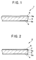
- a method for the production of a magnetic recording medium in the simplest form i.e. a magnetic recording medium 1 which, as illustrated in Fig. 1, is provided on one surface 5a of a nonmagnetic support 5 with a magnetic layer 6 and on the other surface 5b of the nonmagnetic support 5 with a backcoat layer 4.
- Fig. 4 is a schematic production process diagram depicting a method for the production of this magnetic recording medium 1.
- an unwinding device which is provided with an unwinding roll 11 having a nonmagnetic support 5 wound thereon is positioned on the most upstream side.
- a device for applying a magnetic paint such as, for example, an extrusion nozzle 20
- a device for applying a paint for the formation of a backcoat layer such as, for example, an extrusion nozzle 30
- a magnetic field orienting device 40 a drying device 50, a calendering device 60, and a rewinding device (not shown) are sequentially laid out toward the downstream side from the unwinding roll 11.
- the method of production according to this invention starts applying the magnetic paint for the formation of the magnetic layer by the use of the coating device (such as, for example, the extrusion nozzle 20) to the one surface 5a of the nonmagnetic support 5 continuously running (along the direction of an arrow ( ⁇ )).
- the coating device such as, for example, the extrusion nozzle 20
- the surface of the nonmagnetic support 5 prior to the application thereto of the paint is often treated, for the purpose of cleaning and surface control, by a varying known contrivance such as wet cleaning by the use of water or a solvent, dry cleaning by the use of a wiper of non-woven fabric or woven fabric of microfine fibers, or non-contact type cleaning by the use of compressed air, vacuum, or ionized air.
- the surface of the nonmagnetic support 5 is often subjected, for the purpose of ensuring fast adhesion of the paint to the nonmagnetic support 5 and improving the quality of surface for application, to a varying known non-contact surface treatment such as corona discharge, ultraviolet light irradiation, or electron beam irradiation.
- the surface is undercoated with a water type undercoating agent, an emulsion type undercoating agent, or a solvent type undercoating agent either alone or in combination with the surface treatment mentioned above for the purpose of enhancing the fast adhesion.
- the wet surface of the film of the magnetic paint deposited on the nonmagnetic support may be given a varying treatment for smoothing the surface or regulating the applied film.
- a film or a bar made of a resinous, metallic, or ceramic substance may be used for contact smoothing or a magnetic field with a permanent magnet or an electromagnet or vibration with ultrasonic wave for noncontact smoothing.
- a paint for the formation of the backcoat layer is immediately applied by the use of a coating device (such as, for example, the extrusion nozzle 30) to the other surface 5b of the nonmagnetic support 5 which is continuously running.
- a coating device such as, for example, the extrusion nozzle 30
- the method of coating according to this invention is implemented most advantageously by a procedure of applying the magnetic paint and the paint for the formation of the backcoat layer substantially simultaneously to the opposite surfaces of the nonmagnetic support 5 and drying the applied layers of the paints with one and the same drying means.
- the coating device disposed on the most upstream side may be a gravure coater, a reverse roll coater, or an extrusion nozzle and the coating device on the downstream side must be an extrusion nozzle.
- the paints the magnetic paint and the paint for the formation of the backcoat layer
- the two coating devices must be both an extrusion nozzle. Concerning this application of the paints to the opposite surfaces, the present patent applicant has already proposed the best method of application (JP-A-07-185,449 and JP-A-07-185,437).
- Two orienting magnets 41 of the magnetic field orienting device are set applying a magnetic field to effect an orienting treatment (the step for the orienting treatment) after the application of the magnetic paint for the formation of the magnetic layer and the paint for the formation of the backcoat layer severally to the opposite surfaces of the nonmagnetic support 5 and before the magnetic paint for the formation of the magnetic layer has dried.
- the paint for the formation of the backcoat layer exists in an undried state on the reverse surface of the nonmagnetic support 5
- the retention of "the magnetic paint for the formation of the magnetic layer in an undried state" can be easily attained even when the applied coating of the magnetic layer has a small thickness.
- the essence of the method of production according to this invention consists in retaining the magnetic coating in a wet state and meanwhile applying a magnetic field on the magnetic coating in the undried state by ensuring the presence of a backcoat layer in an infallibly undried state (particularly in a wet state) while the magnetic coating is in the undried state (particularly in the wet state) (in other words, by causing the two paints to retain an undried state at the time that the application of these paints is completed). So long as the state essential for this invention is retained intact, the sequence in which the application of the magnetic paint for the formation of the magnetic layer and that of the paint for the formation of the backcoat layer may be changed as a modification of the method of production mentioned above.
- the extrusion nozzle 20 may be actuated first to apply the paint for the formation of the backcoat layer and then the extrusion nozzle 30 may be actuated to apply the magnetic paint for the formation of the magnetic layer.
- the extrusion nozzle 20 may be actuated first to apply the paint for the formation of the backcoat layer and then the extrusion nozzle 30 may be actuated to apply the magnetic paint for the formation of the magnetic layer.
- the orienting treatment may be performed, as illustrated in Fig. 4, on the magnetic coating by means of the orienting magnets 41 after the magnetic coating has been predried with hot air nozzles 53 prior to reaching the orienting magnets in the drying oven.
- the reference numeral 54 denotes each of a plurality of hot air nozzles laid out on the downstream side of the orienting magnets 41.
- the orienting magnets do not need to be limited to one pair as illustrated in the diagram but may be in a larger number and disposed at a plurality of steps inside the drying oven.
- the orienting treatment under discussion brings about the same effect when orienting magnets of a first stage (not shown) are disposed between the extrusion nozzle 30 and the entrance to the drying oven and orienting magnets of a last stage are disposed inside the drying furnace.
- this treatment is performed for the purpose of orienting the magnetic powder in the magnetic layer and this orientation may be made in a longitudinal, perpendicular, or oblique direction relative to the direction of running of the medium.
- This orientation is effected by the use of varying magnetic field-generating means such as a permanent magnet like a ferrite magnet or a rare earth magnet, an electromagnet, or a solenoid. Two or more species of these magnetic field-generating means may be used in combination.
- the wet magnetic coating may be subjected to a step of moderate drying prior to or simultaneously with the orienting treatment.
- the applied coatings are dried by the use of a drying device 50 (drying oven),
- the drying device 50 illustrated in Fig. 4 is adapted to dry the wet coatings with the hot air which is spouted through the hot air nozzles 53 and 54.
- the wet coatings may be otherwise dried and fixed by any of known drying and evaporating means such as an infrared ray emitter, an electric heater, or a vacuum device or any of various known curing devices such as an ultraviolet light lamp or a radiation emitter.
- the drying temperature may be suitably selected in the approximate range of room temperature - 300 °C, depending on such factors as the ability of the nonmagnetic support to withstand heat and the kind and concentration of the solvent.
- the interior of the drying oven may be adapted to produce a temperature gradient and the gaseous environment inside the drying oven may be formed of ordinary air or an inert gas.
- an ultraviolet lamp or a radiation emitter is used for drying the wet coating, it possibly induces a curing reaction in the coating.
- some other drying means so far as circumstances permit.
- the coating still containing the solvent is exposed to the ultraviolet light or the radiation, it possibly catches fire or emits smoke. Again in this case, it is appropriate to use additionally some other drying means so far as circumstances permit.
- the coatings (the magnetic layer and the backcoat layer) which have undergone the orienting treatment and the drying treatment mentioned above properly are subjected to an in-line calendering treatment by the use of the calendering device 60.
- the magnetic recording medium already furnished with the magnetic layer and the backcoat layer is calendered on the in-line system, it acquires a conspicuous improvement in the surface processibility of the magnetic layer and consequently in such properties as electromagnetic conversion property.
- the treatment is continuously carried out on the in-line system, the loss of the applied layer of the paint which used to occur because of the separation of the coating line and the calendering line in the conventional process.
- the calendering device 60 for performing the calendering work is provided, as illustrated in Fig. 4, with a plurality of calendering rolls 61 and 62 which are arranged in a row.
- the nonmagnetic support having the magnetic layer and the backcoat layer already formed thereon is passed as pressed and heated between the calendering rolls.
- the calendering rolls 61 illustrated in Fig. 4 are disposed on the side for contact with the obverse surface of the magnetic layer and the calendering rolls 62 on the side for contact with the reverse surface of the nonmagnetic support (the side basing the backcoat layer).
- the calendering rolls 61 on the side for contact with the magnetic surface are generally metallic rolls and the calendering rolls 62 on the side for contact with the reverse surface of the nonmagnetic support may be either resinous rolls or metallic rolls.
- resinous rolls such heat-resistant plastic rolls as are formed of epoxy, polyester, nylon, polyimide, or polyimideamide (which may incorporate therein carbon, metal, or some other inorganic compound) are used.
- These calendering rolls 61 and 62 are generally used as combined in three to seven steps (seven steps of rolls depicted in Fig. 4).
- the calendering temperature is not less than 70 °C, preferably not less than 80°C.
- the upper limit of this temperature is variable with the kind of the support to be used, it is properly set at 150 °C.
- the linear pressure with which the magnetic recording medium is nipped between the opposed rolls is appropriately not less than 200 kg/cm, preferably not less than 300 kg/cm.
- the speed of running of the nonmagnetic support through the interfaces of the opposed rolls depends on the speed of the coating device because of the in-line system, it is generally in the range of 20 m/minute - 700 m/minute.
- the magnetic recording medium after undergoing the calendering treatment, is appropriately subjected to the thermal curing treatment at a temperature in the range of 40 - 80 °C and/or the treatment with an electron beam for the purpose of accelerating the curing of the magnetic layer and the backcoat layer.
- the magnetic recording medium is given a prescribed shape of tape by the use of slitters and the magnetic surface and/or the backcoat surface is given such a secondary processing as polishing and cleaning, to complete a magnetic recording medium.
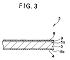
- the magnetic recording medium to which this mode of the invention is directed is a magnetic recording medium 2 which, as illustrated in Fig. 2, is provided on one surface 5a of the nonmagnetic support 5 with a lower magnetic layer 7, on the lower magnetic layer 7 with an upper magnetic layer 8, and on the other surface 5b of the nonmagnetic support 5 with a backcoat layer 4.
- the essence of this invention regarding the production consists in retaining the magnetic coating of the upper magnetic layer 8 in a wet state and meanwhile applying a magnetic field on the magnetic coating in the undried state by ensuring the presence of a backcoat layer in an infallibly undried state (particularly in a wet state) while the magnetic coating of at least the upper magnetic layer 8 is in the undried state (particularly in the wet state).
- the orienting treatment is preferably embodied by applying a magnetic field on the magnetic coatings of the upper magnetic layer 8 and the lower magnetic layer 7 meanwhile keeping these magnetic coatings in a wet state by ensuring the presence of a backcoat layer in an infallibly undried state (particularly in a wet state) while the magnetic coatings of the upper magnetic layer 8 and the lower magnetic layer 7 are in the undried state (particularly in the wet state).
- the orienting treatment, the drying treatment, and the calendering treatment are carried out.
- the backcoat layer exists in an infallible undried state (particularly in a wet state) while the magnetic coating of the upper magnetic layer 8 is in an undried state (particularly in a wet state).
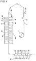
- the magnetic recording medium to which this mode of the invention is directed is a magnetic recording medium 3 which, as illustrated in Fig. 3, is provided on one surface 5a of the nonmagnetic support 5 with a nonferromagnetic undercoat layer 9, on the nonferromagentic undercoat layer 9 with an upper magnetic layer 8, and on the other surface 5b of the nonmagnetic support 5 with a backcoat layer 4.
- the essence of this invention regarding the production consists in retaining the magnetic coating of the upper magnetic layer 8 in a wet state and meanwhile applying a magnetic field on the magnetic coating in the undried state by ensuring the presence of a backcoat layer in an infallibly undried state (particularly in a wet state) while the magnetic coating of at least the upper magnetic layer 8 is in the undried state (particularly in the wet state).
- the orienting treatment is alternatively embodied by applying a magnetic field on the coatings of the upper magnetic layer 8 and the nonferromagnetic undercoat layer 9 meanwhile keeping these coatings in a wet state by ensuring the presence of a backcoat layer in an infallibly undried state (particularly in a wet state) while the coatings of the upper magnetic layer 8 and the nonferromagnetic undercoat layer 9 are in the undried state (particularly in the wet state).
- the orienting treatment, the drying treatment, and the calendering treatment are carried out.
- the backcoat layer exists in an infallible undried state (particularly in a wet state) while the coatings of the upper magnetic layer 8 and the nonferromagnetic undercoat layer 9 are an undried state (particularly in a wet state).
- the backcoat layer exists in an infallible undried state (particularly in a wet state) while the magnetic coating of the upper magnetic layer 8 is in an undried state (particularly in a wet state).
- the magnetic paint contains as principal components thereof a ferromagnetic powder, a binder, and a solvent.
- iron oxide type magnetic powders such as ⁇ -Fe 2 O 3 coated or doped with a Co compound.
- ferromagnetic iron or alloy powders having ferromagnetic metal elements like ⁇ -Fe, Fe-Co, Fe-Ni, Fe-Co, Ni, Co, and Co-Ni as a principal component thereof; CrO 2 magnetic powder; and plate hexagonal ferrite powder having an easy magnetizing axis in a direction perpendicular to the plate thereof may be cited.
- the ferromagnetic powder may incorporate therein Al, Si, P, Y, or a rare earth element for the purpose of preventing the magnetic powder itself from being sintered, improving the particle size distribution thereof, and consequently enhancing the electromagnetic conversion property of the magnetic recording medium.
- a coupling agent such as Si, Al, or Ti or a varying surfactant
- the ferromagnetic paint is enabled to acquire improved dispersibility and the ultimately produced magnetic recording medium is enabled to acquire improved durability.
- the binder to be contained in the magnetic paint may be any of the binder resins such as thermoplastic resins, reactive resins, and electron beam curing resins which are used generally for the formation of a magnetic layer in a magnetic recording medium.
- the thermoplastic resin has a softening point of 150°C or less and an average molecular weight in the approximate range of 5000 - 200000.
- vinylchloride type copolymers, polyurethane resins, (meth)acrylic resins, polyester resins, nitrocellulose, and phenoxy type resins may be cited.
- those reactive resins having a hydroxyl group at the terminal and/or in the side chain of a copolymer prove particularly advantageous because they are capable of easily utilizing the cross-linkage by the use of an isocyanate or the electron-beam cross-linkage due to an electron beam functional type modification.
- the average molecular weight and the polymerization degree thereof are on a part with those of the thermoplastic resin serving as a basis.
- This binder resin appropriately incorporates therein through copolymerization or addition reaction at least one polar group, namely a hydrophilic functional group.
- this polar group contributes to the improvement of the dispersibility of the paint and consequently to the improvement of the characteristic properties of the magnetic recording medium.
- the polar group may be present in the main chain or in the branch of the skeleton resin. Though these resins may be used singly, the use of a combination of two or more of these resins allows the various properties of the magnetic recording medium to be improved. Among other conceivable combinations of these resins, the combinations of such vinyl chloride type copolymers as shown below with polyurethane resin prove particularly appropriated.
- the vinyl chloride type copolymer appropriately has a vinyl chloride content in the range of 60 - 95 wt%, preferably 60 - 90 wt% and an average polymerization degree in the approximate range of 100 - 500.
- the vinyl chloride type copolymer is obtained by copolymerizing such a copolymerizing monomer as vinyl chloride, vinyl acetate, vinyl alcohol capable of incorporating therein vinyl acetate through saponification, hydroxyalkyl (meth)-acrylate, maleic acid, glycidyl (meth)acrylate, and allyl glycidyl ether.
- the copolymer incorporates therein through copolymerization or addition reaction at least one polar group selected from the class of polar groups mentioned above.
- the -NR 2 group proves particularly advantageous because it is capable of improving the physical properties (such as the stability of storage) of the paint when it is used in combination with a polar group originating in the acid mentioned above.
- polyurethane resin is a general term which is applied to such resins as are produced by the reaction of such hydroxyl group-containing resins as polyester polyols and/or polyether polyols with a polyisocyanate-containing compound. It is obtained by polymerizing such raw materials for synthesis as mentioned above until a number-average molecular weight in the approximate range of 5000 - 200000. It must possess a O value (weight average molecular weight/number average molecular weight) that falls in the approximate range of 1.5 - 4.
- At least two urethane resins are used which, in the binder to be used, manifest different glass transition points, Tg, in the range of -30 °C ⁇ Tg ⁇ 80°C and the total amount of the urethane resins is in the range of 10 - 90 wt% of the total amount of the binder.
- Tg glass transition point
- the polyurethane resin (at least one when two or more species are used) incorporates therein the polar group mentioned above.
- the vinyl chloride type copolymer and the polyurethane resin are appropriately used at a gravimetric mixing ratio in the range of 10 : 90 - 90 : 10.
- the cross-linking agent which is used for hardening the binder resin may be any of various known polyisocyanates. This cross-linking agent three-dimensionally binds the hydroxyl groups contained in the binder resin and consequently enables the produced coating to be improved in durability.
- the copolymer mentioned above may have the sensitivity thereof to electron beam modified by incorporating therein a (meth)acrylic type double bond by a known technique.
- the solvent to be contained in the magnetic paint is not particularly limited. It is selected in consideration of the solubility, compatibility, drying efficiency, etc. of the binder to be used.
- the solvent which is advantageously used herein ketones such as methylethyl ketone, methyl isobutyl ketone, and cyclohexanone; aromatic hydrocarbons such as toluene and xylene; esters such as ethyl acetate and butyl acetate; alcohols such as isopropanol and butanol; and chlorine-substituted hydrocarbons such as dioxane, tetrahydro-furan, dimethyl formamide, and hexane may be cited.
- These diluents or solvents may be used either singly or in the form of a mixture of two or more members combined at an arbitrary ratio.
- the magnetic paint generally contains a lubricant.
- fatty acids and/or fatty acid esters prove particularly advantageous.
- monobasic fatty acids having 12 - 24 carbon atoms may be cited.
- fatty acid ester used herein monofatty acid esters, difatty acid esters, and trifatty acid esters which use as raw materials thereof a monobasic fatty acid of 10 - 24 carbon atoms and one alcohol selected from the group consisting of univalent to hexavalent alcohols of 2 - 22 carbon atoms and cyclic or polysaccharide-reduced alcohols may be cited.
- the hydrocarbon groups in the fatty acids and fatty acid esters may contain an unsaturated bond or may be branched. Two or more of these lubricants may be used in combination.
- the backcoat layer and the undercoat layer properly contain the lubricant. Particularly when the magnetic layers have small thicknesses, the incorporation of the lubricant in the undercoat layer is effective in improving the still durability of the produced magnetic recording medium. Further, when the lubricant content is increased on the backcoat layer side, the lubricant transferred to the surfaces of the magnetic layers can contribute to the improvement of the surface lubricity of the magnetic layers.
- the magnetic paint contains additives which are intended to manifest a lubricating effect, an antistatic effect, a dispersing effect, and a plasticizing effect.
- the additives which are usable for this purpose include silicon oils, fluorine oils, cationic surfactants, nonionic surfactants, anionic surfactants, and amphoteric surfactants, for example.
- the magnetic paint further contains inorganic compounds, particularly abrasive and nonferromagnetic pigment.
- inorganic compounds particularly abrasive and nonferromagnetic pigment.
- ⁇ -alumina, ⁇ -alumina, ⁇ -alumina, dichromium trioxide, ⁇ -iron oxide, SiO 2 , ZnO, TiO 2 , silicon carbide, calcium carbonate, and barium sulfate may be cited.
- the shape, size, etc. of the particles of the pigment may be arbitrarily set, the particles properly have a spherical shape or a polyhedral shape.
- the particles appropriately have diameters in the range of 0.01 - 0.7 ⁇ m and, when necessary, may be suitably selected, depending on the balance between the durability expected of the medium and the abrasion of the head and the output at the shortest recording wavelength.
- the pigments cited above may be used either singly or in the form of a mixture of two or more members.
- the magnetic paint may contain carbon black.
- carbon black As concrete examples of the carbon black which is effectively used herein, furnace carbon black, thermal carbon black, and acetylene black may be cited. These species of carbon black may be used either singly or in the form of a mixture of two or more members.
- the carbon black may be given a surface treatment with a lubricant or a dispersant or may have part of the surface thereof grafted before it is put to use herein.
- the particle size of the carbon black may be arbitrarily set, it is appropriately selected, depending on the balance among the electric resistance, friction properties, and the output (surface roughness) at the shortest recording wavelength expected of the medium.
- the magnetic paint may contain a nonmagnetic organic powder (organic pigment).
- a nonmagnetic organic powder organic pigment
- the solids concentration in the magnetic paint is appropriately set at a level in the range of 5 - 45% by weight, preferably 10 - 40% by weight. If this concentration is less than 5% by weight, the magnetic paint will no longer be able to produce a uniform coating. Conversely, if this concentration exceeds 45% by weight, the wet coating of the magnetic layer will dry so quickly that the improvement of the degree of orientation of the magnetic layer aimed at by this invention will not be easily attained. Particularly in the case of the upper magnetic layer, when the coating of the undercoat layer is in a dried state as in the procedures of (2-6), (2-7), (3-6), and (3-7) mentioned above, the trend indicated above grows conspicuous because the solvent in the coating of the magnetic layer migrates to the undercoat layer .
- the films of polyethylene terephthalate (PET), polyethylene naphthalate (PEN), polyamide, polyimide, and polyamideimide may be cited.
- PET, PEN, and aromatic polyamide prove particularly favorable.
- a composite film produced by coextruding two or three species of PET or PEN proves especially favorable.
- the nonmagnetic support may be subjected preparatorily to a corona discharge treatment, a plasma discharge and/or polymerization treatment, a treatment for application of adhesive agent, a dust proofing treatment, and a moderating treatment with heat and/or by adjustment of moisture.
- the paint for the formation of the backcoat layer 4 is applied to the surface of the nonmagnetic support opposite the surface thereof to which the magnetic paint is applied.
- the paint for the formation of the backcoat layer contains carbon black or an inorganic compound, a binder, and a solvent as main components thereof. These main components may be suitably selected from among the carbon blacks or inorganic compounds. binders, and solvents cited above by way of illustration in the passage concerning the magnetic paints, so as to meet the properties demanded.
- the paint may contain a lubricant and varying additives which are to be suitably selected from among the concrete examples cited above by way of illustration in the passage concerning the magnetic paints.
- the solids concentration in the paint for the formation of the backcoat layer 4 is appropriately set at a level in the range of 8 - 30% by weight, preferably 10 - 25% by weight. If this concentration is less than 8% by weight, the paint will no longer be capable of forming a uniform coating. Conversely if this concentration exceeds 30% by weight, the wet coating of the magnetic layer will dry so quickly that the improvement of the degree of orientation of the magnetic layer aimed at by this invention will not be easily attained.
- the components may be suitably selected from among the binders, solvents, lubricants, carbon blacks, inorganic compounds, and various additives cited above by way of illustration in the passage concerning the magnetic paints.
- the solids concentration in the paint for the formation of the nonferromagnetic undercoat layer 9 is properly in the range of 5 - 45% by weight, preferably 10 - 40% by weight. If this concentration is unduly low or unduly high, the paint will produce a uniform coating only with difficulty.
- the process for producing the magnetic paints (for the upper and the lower layers) and that for producing the paints for the formation of the magnetic recording medium (the paint for the formation of the backcoat layer and the paint for the formation of the nonferromagnetic undercoat layer) which are used in the method for the production of the magnetic recording medium of this invention each comprise at least 1 a kneading step, 2 a dispersing step, 3 a filtering step, 4 a mixing step which is optionally placed before or after any of the steps mentioned above, and 5 a storing step.
- the pigment powder and the whole or part of the binder are kneaded by the use of a kneading device of strong kneading force such as, for example, a continuous kneader, a pressure kneader, a high-speed mixer, or a two roll mill.
- a kneading device of strong kneading force such as, for example, a continuous kneader, a pressure kneader, a high-speed mixer, or a two roll mill.
- the paint is dispersed by the use of zirconia or glass beads.
- the operation of dispersion is carried out in combination with an operation of dilution which is intended to effect gradual decrease of the solids concentration.
- the component steps may be severally divided into two or more stages.
- the raw materials may be added, as divided, at two or more of the component steps.
- the step of filtering the paint is placed after each of the processes of production mentioned above. If the magnetic paint entrains an undispersed portion or an agglomerated portion of the magnetic powder or resinous insolubles, it will entail the disadvantage of aggravating dropout and heightening the error rate.
- the filtering step is aimed primarily at deriving the magnetic paint of an extraneous substance.
- the magnetic recording medium which is formed by the method of production according to this invention is provided, as described above, with one or a plurality (preferably two) magnetic layers.
- the thickness of this magnetic layer is generally 3.0 ⁇ m or less, especially 0.1 - 3.0 ⁇ m, preferably 2.5 ⁇ m or less, especially 0.3 - 2.5 ⁇ m. If the thickness exceeds 3.0 ⁇ m, the drying speed of the coating of the magnetic layer will be lowered and the degree of orientation of the magnetic layer will not be increased in spite of the orienting treatment. Then, the self-demagnetization loss will increase when the recording wavelength is short.
- the thickness of the uppermost magnetic layer is generally 1.0 ⁇ m or less, especially 0.05 - 1.0 ⁇ m, preferably 0.6 ⁇ m or less, especially 0.1 - 0.6 ⁇ m. If this thickness exceeds 1.0 ⁇ m, the provision of the lower layer will become meaningless as compared with the magnetic layer which is provided solely.
- the thickness of the backcoat layer is set at a level in the range of 0.1 - 2.0 ⁇ m. If this thickness is less than 0.1 ⁇ m, the wet coating of the backcoat layer will dry so quickly that the improvement of the degree of orientation of the magnetic layer aimed at by this invention will not be easily attained. Then, the backcoat layer will be readily scraped while the medium is running. If this thickness exceeds 2.0 ⁇ m, the medium will produce increased friction with the path on which the medium slides, the running stability of the medium will be impaired, and the wet coating of the magnetic layer will dry so slowly as to give rise to the possibility of rather degrading than improving the orientation of the magnetic layer.
- the thickness of the nonferromagnetic undercoat layer is set at a level in the range of 0.1 - 3.0 ⁇ m. If this thickness is less than 0.1 ⁇ m, the nonferromagnetic undercoat layer will be susceptible of the influence of the surface quality of the nonmagnetic support and consequently the surface coarseness of the nonferromagnetic layer will be degraded and the surface coarseness of the uppermost magnetic layer will be likewise degraded. As a result, the electromagnetic conversion property will tend to decline. If the thickness of the nonferromagnetic undercoat layer is increased beyond 3.0 ⁇ m, the excess will bring about no noticeable improvement of the quality of the layer. Then, the absorption of the solvent from the magnetic layer will grow to a point where the effect of this invention will be no longer attained.
- the thickness of the lower magnetic layer is set at a level in the range of 0.1 - 3.0 ⁇ m. If this thickness is less than 0.1 ⁇ m, the lower magnetic layer will be susceptible of the influence of the surface quality of the nonmagnetic support and consequently the surface coarseness of the nonferromagnetic layer will be degraded and the surface coarseness of the uppermost magnetic layer will be likewise degraded. As a result, the electromagnetic conversion property will tend to decline. If the thickness of the lower magnetic layer is increased beyond 3.0 ⁇ m, the excess will bring about no noticeable improvement of the quality of the layer. Then, the absorption of the solvent from the magnetic layer will grow to a point where the effect of this invention will not be easily attained.
- the thickness and the solids concentration in each of the layers are closely related.
- the backcoat layer appropriately has a thickness of not less than 1/2 of the thickness of the magnetic layer.
- the solids concentration when the thickness of the magnetic layer is 1 ⁇ m or less, the backcoat layer appropriately has a solids concentration not more than that of at least the magnetic layer.
- a magnetic paint I, a magnetic paint II, a paint for the formation of a nonferromagnetic undercoat layer, and a paint for the formation of a backcoat layer were manufactured as follows.
- the mixture resulting from the viscosity adjustment was dispersed by the use of a sand grinding mill.
- the viscosity adjusting liquid resulting from the circulating filtration and the slurry from the dispersing treatment were mixed.
- the mixture was dispersed by the use of a sand grinding mill to adjust the viscosity of the paint to 50 cp and form the paint for a magnetic layer.
- This paint was subjected to 8 hours' circulating filtration by the use of a depth type filter having a 95% cut filtration accuracy of 1.2 ⁇ m.
- the viscosity was determined by the use of a viscometer (produced by Rheology K.K. and marketed under product code of "MR-300”) at a liquid temperature of 20 °C at a shear rate of 3000 sec -1 .
- the paint 1 for the magnetic layer was obtained by adding 0.8 part by weight of an isocyanate compound (produced by Nippon Polyurethane Kogyo K.K. and marketed under trademark designation of "Coronate L") to 100 parts by weight of the paint resulting from the filtration and mixing them by stirring.
- an isocyanate compound produced by Nippon Polyurethane Kogyo K.K. and marketed under trademark designation of "Coronate L"
- the mixture resulting from the viscosity adjustment was dispersed by the use of a sand grinding mill.
- the viscosity adjusting liquid resulting from the circulating filtration and the slurry from the dispersing treatment were mixed.
- the mixture was dispersed by the use of a sand grinding mill to adjust the viscosity of the paint to 40 cp and form the paint for a magnetic layer.
- This paint was subjected to 8 hours' circulating filtration by the use of a depth type filter having a 95% cut filtration accuracy of 1.2 ⁇ m.
- the procedure for the adjustment of viscosity was the same as mentioned above.
- the paint II for the magnetic layer was obtained by adding 0.8 part by weight of an isocyanate compound (produced by Nippon Polyurethane Kogyo K.K. and marketed under trademark designation of "Coronate L") to 100 parts by weight of the paint resulting from the filtration and mixing them by stirring.
- an isocyanate compound produced by Nippon Polyurethane Kogyo K.K. and marketed under trademark designation of "Coronate L"
- the mixture resulting from the viscosity adjustment was dispersed by the use of a sand grinding mill.
- the viscosity adjusting liquid resulting from the circulating filtration and the slurry from the dispersing treatment were mixed.
- the mixture was dispersed by the use of a sand grinding mill to adjust the viscosity of the paint to 40 cp and form a paint for forming a nonferromagnetic undercoat layer.
- This paint was subjected to 8 hours' circulating filtration by the use of a depth type filter having a 95% cut filtration accuracy of 1.2 ⁇ m.
- the procedure for the adjustment of viscosity was the same as mentioned above.
- the paint for the nonferromagnetic undercoat layer was obtained by adding 0.8 part by weight of an isocyanate compound (produced by Nippon Polyurethane Kogyo K.K. and marketed under trademark designation of "Coronate L") to 100 parts by weight of the paint resulting from the filtration and mixing them by stirring.
- an isocyanate compound produced by Nippon Polyurethane Kogyo K.K. and marketed under trademark designation of "Coronate L
- This binder solution was subjected to 8 hours' circulating filtration by the use of a depth type filter having a 95% cut filtration accuracy of 5.0 ⁇ m to prepare a finished binder solution.
- the mixture resulting from the viscosity adjustment was dispersed by the use of a sand grinding mill.
- the viscosity adjusting liquid resulting from the circulating filtration and the slurry from the dispersing treatment were mixed.
- the mixture was dispersed by the use of a sand grinding mill to adjust the viscosity of the paint to 10 cp and form the paint for a backcoat layer.
- This paint was subjected to 8 hours' circulating filtration by the use of a depth type filter having a 95% cut filtration accuracy of 1.2 ⁇ m.
- the procedure for the adjustment of viscosity was the same as mentioned above.
- the paint for the backcoat layer was obtained by adding 1.0 part by weight of an isocyanate compound (produced by Nippon Polyurethane Kogyo K.K. and marketed under trademark designation of "Coronate L") to 100 parts by weight of the paint resulting from the filtration and mixing them by stirring.
- an isocyanate compound produced by Nippon Polyurethane Kogyo K.K. and marketed under trademark designation of "Coronate L"
- a coating for the formation of a magnetic layer was formed continuously by discharging the magnetic paint I mentioned above through the extrusion nozzle 20 of the apparatus illustrated in Fig. 4 onto one surface of a polyethylene terephthalate support, 15.0 ⁇ m in thickness, which was continuously running.
- a coating for the formation of a backcoat layer was continuously formed by discharging the paint for the format ion of the backcoat layer through the extrusion nozzle 30 onto the other surface of the support while the coating for the formation of the magnetic layer was still in a wet state. Then, the magnetic layer (and the backcoat layer) was predried by means of the hot air nozzle 53 and subsequently passed along the orienting magnets 41 while the magnetic layer was in an undried state to effect orientation of the magnetic powder in the direction of running. Thereafter, the magnetic layer (and the backcoat layer) was dried and the support carrying the dried coating was provisionally rewound.
- calendering device provided with seven steps of calender rolls
- this support was given a calendering treatment at a temperature of 110°C under a linear pressure of 300 kg/cm to smooth the surface of the coating.
- Fig. 4 depicts a calendering treatment performed on the in-line system
- the calendering treatment in the present test example 1 was carried out in a manner different from the in-line system illustrated in Fig. 4.
- Coating method A1 This comprises applying the paint for the magnetic layer and then applying the paint for the backcoat layer while the coating of the magnetic layer was in a wet state (corresponding to the applying method described above).
- Coating method A2 This comprises applying the paint for the backcoat layer and then applying the paint for the magnetic layer while the paint for the backcoat layer was in a wet state.
- Coating method B1 This comprised applying the paint for the magnetic layer, subjecting the resultant coating to an orienting treatment, a drying treatment, and a calendering treatment, and then applying the paint for the backcoat layer.
- the magnetic property of a tape sample was measured by the use of a vibrating sample magnetometer (produced by Toei Kogyosha K.K. and marketed under product code of "VSM-V") using a maximum external magnetic field of 10 kOe.
- the degree of orientation is defined by the expression, (Br/Bm) MD /(Br/Bm) TD , wherein Bm represents a saturated magnetic flux density, MD the longitudinal direction of the tape, and TD the lateral direction of the tape.
- Table 1 Sample No. Magnetic Layer BC Layer Coating Method Degree of Orientation Br Magnetic Paint Thickness ( ⁇ m) Thickness ( ⁇ m) I- 1 Paint I 2.0 0.5 A1 2.90 1780 I- 2 Paint I 2.5 0.5 A1 2.95 1800 I- 3 Paint II 0.8 0.5 A1 2.80 2900 I- 4 Paint II 0.3 0.2 A1 2.60 2800 I- 5 Paint II 0.3 0.5 A1 2.75 2890 I- 6 Paint II 0.3 2.0 A1 2.70 2860 I- 7 Paint II 2.0 0.5 A1 2.77 2890 I- 8 Paint I 2.0 0.5 A2 2.92 1800 I- 9 Paint II 0.8 0.5 A2 2.83 2930 I-10 Paint II 0.3 0.2 A2 2.63 2830 I-11 Paint II 0.3 0.5 A2 2.77 2900 I-12 Paint II 0.3 2.0 A2 2.73 2850 I-13 Paint II 2.0 0.5 A2 2.78 2900 I-14* Paint I 2.0 0.5 B1 2.35 1600 I-15* Paint I 2.5 0.5 B1 2.45 1640 I-16*
- the magnetic paint I and the magnetic paint II were continuously discharged through the two closely disposed extrusion nozzles onto one surface of a continuously running polyethylene terephthalate support, 8.3 ⁇ m in thickness, to form continuously a laminate of the coating for the formation of a lower magnetic layer and the coating for the formation of an upper magnetic layer.
- the paint for the formation of the backcoat layer was discharged through the extrusion nozzle 30 onto the other surface of the support while the coatings for the formation of the two magnetic layers were in a wet state to form continuously the coating for the formation of the backcoat layer.
- the two magnetic layers (and the backcoat layer) were predried by the use of the hot air nozzle 53 and were passed along the orienting magnets 41 while the two magnetic layers were in an undried state to effect orientation of the magnetic powder in the direction of running. Then, the two magnetic layers (and the backcoat layer) were dried and the support carrying the dried coatings was provisionally rewound.
- this support carrying the dried coatings was given a calendering treatment at a temperature of 110 °C under a linear pressure of 300 kg/cm to smooth the surface of the coating.
- the calendering treatment in the present test example 2 was carried out in a manner different from the in-line system illustrated in Fig. 4.
- coating method A3, coating method A4, coating method A5, coating method A6, coating method A7, and coating method B2 By producing the upper magnetic layer and the lower magnetic layer in varied thicknesses and adopting six coating methods, i.e. coating method A3, coating method A4, coating method A5, coating method A6, coating method A7, and coating method B2, the various samples II-1 - II-9 shown in the following Table 2 were manufactured.
- Coating method A3 This comprised applying the paint for the lower magnetic layer, applying the paint for the upper magnetic layer while the paint for the lower magnetic layer was in a wet state, and applying the paint for the backcoat layer while the paints for the two magnetic layers were in a wet state (corresponding to the coating method described above).
- Coating method A4 This comprised applying the paint for the backcoat layer and then applying the paint for the lower magnetic layer and the paint for the upper magnetic layer sequentially in the order mentioned while the paint for the backcoat layer was in a wet state (at which time the paints for the two magnetic layers were each in a wet state).
- Coating method A5 This comprised simultaneously applying the paint for the lower magnetic layer and the paint for the upper magnetic layer in a superposed manner and then applying the paint for the backcoat layer while the paints for the two magnetic layers were in a wet state.
- Coating method A6 This comprised applying the paint for the backcoat layer and then applying the paint for the lower magnetic layer and the paint for the upper magnetic layer simultaneously while the paint for the backcoat layer was in a wet state.
- Coating method A7 This comprised applying the paint for the lower magnetic layer, applying the paint for the backcoat layer while the paint for the lower magnetic layer was in a wet state, and applying the paint for the upper magnetic layer while the paints for the two layers mentioned above were in a wet state.
- Coating method B2 This comprised applying the paint for the lower magnetic layer, applying the paint for the upper magnetic layer while the paint for the lower magnetic layer was in a wet state, subjecting the two coatings consequently formed to an orienting treatment, a drying treatment, and a calendering treatment, and thereafter applying the paint for the backcoat layer.
- the magnetic paint I mentioned above was applied to one surface of a continuously running polyethylene terephthalate support, 8.3 ⁇ m in thickness, to form the coating of the lower magnetic layer and the coating thus formed was subjected to an orienting treatment, a drying treatment, and a calendering treatment. Then, the magnetic paint II mentioned above was applied by means of the extrusion nozzle to the lower magnetic layer to form the coating of the upper magnetic layer and the paint for the formation of the backcoat layer was discharged through the extrusion nozzle to the other surface of the support while the coating for the formation of the upper magnetic layer was in a wet state to form the coating for the formation of the backcoat layer continuously.
- the upper magnetic layer (and the backcoat layer) was predried by the hot air nozzle and passed along the orienting magnets while the upper magnetic layer was in an undried state to effect orientation of the magnetic powder in the direction of running. Subsequently, the upper magnetic layer (and the backcoat layer) was dried and the support carrying the dried coating was provisionally rewound.
- this support carrying the dried coating was given a calendering treatment at a temperature of 110 °C under a linear pressure of 300 kg/cm to smooth the surface of the coating.
- the calendering treatment in the present test example 3 was carried out in a manner different from the in-line system illustrated in Fig. 4.
- Coating method A8 This comprised applying the paint for the lower magnetic layer, subjecting the coating consequently formed to an orienting treatment, a drying treatment, and a calendering treatment, then applying the paint for the upper magnetic layer, and applying the paint for the backcoat layer while the paint for the upper magnetic layer was in a wet state (corresponding to the coating method described above).
- Coating method A9 This comprised applying the paint for the lower magnetic layer, subjecting the coating consequently formed to an orienting treatment, a drying treatment, and a calendering treatment, then applying the paint for the backcoat layer, and applying the paint for the upper magnetic layer while the paint for the backcoat layer was in a wet state (at which time, the paint for the upper magnetic layer was in a wet state).
- Coating method B3 This comprised applying the paint for the lower magnetic layer, subjecting the resultant coating to an orienting treatment, a drying treatment, and a calendering treatment, then applying the paint for the upper magnetic layer, subjecting the upper magnetic layer to an orienting treatment, a drying treatment, and a calendering treatment, and then applying the paint for the backcoat layer.
- the paint for forming the nonferromagnetic undercoat layer and the magnetic paint II mentioned above were continuously discharged through two closed disposed extrusion nozzles onto one surface of a continuously running polyethylene terephthalate support. 8.3 ⁇ m in thickness, to form continuously a laminate of the coating for forming the nonferromagnetic undercoat layer and the coating for forming the upper magnetic layer.
- the paint for forming the backcoat layer was discharged through the extrusion nozzle onto the other surface of the support while the two paints were in a wet state to form continuously the paint for forming the backcoat layer. Then, these paints were predried by the use of the hot air nozzle and passed along the orienting magnets while the upper magnetic layer was in an undried state to effect orientation of the magnetic powder in the direction of running. Subsequently, the upper magnetic layer (and the nonferromagnetic undercoat layer and the backcoat layer) was dried and the support carrying the dried coating was provisionally rewound.
- this support carrying the dried coating was given a calendering treatment at a temperature of 110 °C under a linear pressure of 300 kg/cm to smooth the surface of the coating.
- the calendering treatment in the present test example 4 was carried out in a manner different from the in-line system illustrated in Fig. 4.
- Coating method A10 This comprised applying the paint for the nonferromagnetic undercoat layer, applying the paint for the upper magnetic layer while the paint for the nonferromagnetic undercoat layer was in a wet state, and applying the paint for the backcoat layer while the paints for the two layers were in a wet state (corresponding to the coating method described above).
- Coating method A11 This comprised applying the paint for the backcoat layer and then applying sequentially the paint for the nonferromagnetic undercoat layer and the paint for the upper magnetic layer while the paint for the backcoat layer was in a wet state (at which time the two paints were each in a wet state).
- Coating method A12 This comprised applying the paint for the nonferromagnetic undercoat layer and the paint for the upper magnetic layer simultaneously and applying the paint for the backcoat layer while the paints for the two layers were in a wet state.
- Coating method A13 This comprised applying the paint for the backcoat layer and then applying the paint for the nonferromagnetic undercoat layer and the paint for the upper magnetic layer simultaneously while the paint for the backcoat layer was in a wet state.
- Coating method A14 This comprised applying the paint for the nonferromagnetic undercoat layer, applying the paint for the backcoat layer while the paint for the nonferromagnetic undercoat layer was in a wet state, and applying the paint for the upper magnetic layer while the paints of the two layers were in a wet state.
- Coating method B4 This comprised applying the paint for the nonferromagnetic undercoat layer, applying the paint for the upper magnetic layer while the paint for the nonferromagnetic undercoat layer was in a wet state, subjecting the coatings of the two layers to an orienting treatment, a drying treatment, and a calendering treatment, and then applying the paint for the backcoat layer.
- the paint for the nonferromagnetic undercoat layer was applied to one surface of a continuously running polyethylene terephthalate support. 8.3 ⁇ m in thickness and the coating consequently formed was dried and subjected to a calendering treatment to form the coating of the nonferromagnetic undercoat layer. Then, the magnetic paint II mentioned above was applied by the use of the extrusion nozzle to the nonferromagnetic undercoat layer to form the coating of the upper magnetic layer and the paint for forming the backcoat layer was discharged through the extrusion nozzle onto the other surface of the support while the coating for the formation of the upper magnetic layer was in a wet state to form continuously the coating for the formation of the backcoat layer.
- the upper magnetic layer (and the backcoat layer) was predried by the use of the hot air nozzle and passed along the orienting magnets while the upper magnetic layer was in an undried state to effect orientation of the magnetic powder in the direction of running. Subsequently, the upper magnetic layer (and the backcoat layer and the backcoat layer) was dried and the support carrying the dried coating was provisionally rewound.
- this support carrying the dried coating was given a calendering treatment at a temperature of 110°C under a linear pressure of 300 kg/cm to smooth the surface of the coating.
- the calendering treatment in the present test example 5 was carried out in a manner different from the in-line system illustrated in Fig. 4.
- Coating method A15 This comprised applying the paint for the nonferromagnetic undercoat layer, subjecting the resultant coating to a drying treatment and a calendering treatment, then applying the paint for the upper magnetic layer, and applying the paint for the backcoat layer while the paint for the upper magnetic layer was in a wet state (corresponding to the coating method described above).
- Coating method A16 This comprised applying the paint for the nonferromagnetic undercoat layer, subjecting the resultant coating to a drying treatment and a calendering treatment, applying the paint for the backcoat layer, and applying the paint for the upper magnetic layer while the paint for the backcoat layer was in a wet state (at which time the paint for the upper magnetic layer was in a wet state).
- Coating method B5 This comprised applying the paint for the nonferromagnetic undercoat layer, subjecting the resultant coating to a drying treatment and a calendering treatment, then applying the paint for the upper magnetic layer, subjecting the upper magnetic layer to an orienting treatment, a drying treatment, and a calendering treatment, and then applying the paint for the backcoat layer.
- the calendering operation was carried out on the in-line system. Specifically, the support carrying the dried coating was not provisionally rewound before it was subjected to the calendering treatment and the calendering step was effected on the in-line system as illustrated in Fig. 4.
- the samples VI-1, VI-2, and VI-3 were produced herein in the same manner as the samples I-1, I-2, and I-3 of Test Example 1.
- the calendering operation herein was performed under the same conditions as those of Test Example 1 mentioned above.
- the magnitude, Ra was calculated from the result of the determination.
- the loss was expressed by the quotient in % obtained by dividing the length of loss in the applied layer of paint incurred until completion of the calendering treatment by the length of the applied layer of paint (10000 m).
- the rating was made on the four-point scale, wherein
- Table 6 Sample No. Magnetic Layer BC Layer Calendering Ra ( ⁇ m) Loss of Applied layer of Paint Magnetic Paint Thickness ( ⁇ m) Thickness ( ⁇ m) VI-1 Paint I 2.0 0.5 In-line 5.0 o VI-2 Paint I 2.5 0.5 In-line 4.8 o VI-3 Paint II 0.8 0.5 In-line 4.0 o I- 1 Paint I 2.0 0.5 Separate line 7.2 ⁇ I- 2 Paint I 2.5 0.5 Separate line 6.9 ⁇ I- 3 Paint II 0.8 0.5 Separate line 6.0 ⁇
- the calendering operation was carried out on the in-line system. Specifically, the support carrying the dried coating was not provisionally rewound before it was subjected to the calendering treatment and the calendering step was effected on the in-line system as illustrated in Fig. 4.
- the samples VII-1 and VII-2 were produced herein in the same manner as the samples II-1 and II-2 of Test Example 2.
- the calendering operation herein was performed under the same conditions as those of Test Example 2 mentioned above.
- Table 7 Sample No. Upper Magnetic Layer Lower Magnetic Layer BC Layer Calendering Method Ra ( ⁇ m) Loss of Applied layer of Paint Magnetic Paint Thickness ( ⁇ m) Magnetic Paint Thickness ( ⁇ m) Thickness ( ⁇ m) VII-1 Paint II 0.3 Paint I 1.7 0.5 In-line 4.2 o VII-2 Paint II 0.2 Paint I 1.8 0.5 In-line 4.1 o II-1 Paint II 0.3 Paint I 1.7 0.5 Separate line 6.5 ⁇ II-2 Paint II 0.2 Paint I 1.8 0.5 Separate line 6.6 ⁇
- the calendering operation on the upper and the lower layer was carried out on the in-line system. Specifically, the support carrying the dried coating was not provisionally rewound before it was subjected to the calendering treatment and the calendering step was effected on the in-line system as illustrated in Fig. 4.
- the samples VIII-1 and VIII-2 were produced herein in the same manner as the samples III-1 and III-2 of Test Example 3. The calendering operation herein was performed under the same conditions as those of Test Example 3 mentioned above.
- Table 8 Sample No. Upper Magnetic Layer Lower Magnetic Layer BC Layer Calendering Method Ra ( ⁇ m) Loss of Applied layer of Paint Magnetic Paint Thickness ( ⁇ m) Magnetic Paint Thickness ( ⁇ m) Thickness ( ⁇ m) VIII-1 Paint II 0.3 Paint I 1.7 0.5 In-line 4.6 ⁇ VIII-2 Paint II 0.2 Paint I 1.8 0.5 In-line 4.5 ⁇ III-1 Paint II 0.3 Paint I 1.7 0.5 Separate line 7.0 X III-2 Paint II 0.2 Paint I 1.8 0.5 Separate line 7.2 X
- the calendering operation was carried out on the in-line system. Specifically, the support carrying the dried coating was not provisionally rewound before it was subjected to the calendering treatment and the calendering step was effected on the in-line system as illustrated in Fig. 4.
- the samples IX-1 and IX-2 were produced herein in the same manner as the samples IV-1 and IV-2 of Test Example 4.
- the calendering operation herein was performed under the same conditions as those of Test Example 4 mentioned above. These samples were severally rated for surface roughness, Ra, of the magnetic layer and for loss of the applied layer of the paint. The following methods were used for the rating.
- Table 9 Sample No. Upper Magnetic Layer Nonferrous Magnetic Undercoat Layer BC Layer Calendering Method Ra ( ⁇ m) Loss of Applied layer of Paint Magnetic Paint Thickness ( ⁇ m) Thickness ( ⁇ m) Thickness ( ⁇ m) IX-1 Paint II 0.20 1.80 0.5 In-line 3.8 o IX-2 Paint II 0.15 1.85 0.5 In-line 3.6 o IV-1 Paint II 0.20 1.80 0.5 Separate line 5.7 ⁇ IV-2 Paint II 0.15 1.85 0.5 Separate line 5.6 ⁇
- the calendering operation on the upper and the lower layer was carried out on the in-line system. Specifically, the support carrying the dried coating was not provisionally rewound before it was subjected to the calendering treatment and the calendering step was effected on the in-line system as illustrated in Fig. 4.
- the samples X-1 and X-2 were produced herein in the same manner as the samples V-1 and V-2 of Test Example 5. The calendering operation herein was performed under the same conditions as those of Test Example 5 mentioned above.
- Table 10 Sample No. Upper Magnetic Layer Nonferrous Magnetic Undercoat Layer BC Layer Calendering Method Ra ( ⁇ m) Loss of Applied layer of Paint Magnetic Paint Thickness Thickness ( ⁇ m) Thickness ( ⁇ m) X-1 Paint II 0.20 1.80 0.5 In-line 4.0 ⁇ X-2 Paint II 0.15 1.85 0.5 In-line 4.1 ⁇ V-1 Paint II 0.20 1.80 0.5 Separate line 6.7 X V-2 Paint II 0.15 1.85 0.5 Separate line 6.5 X
- this invention allows production of a coating excelling in the degree of orientation in spite of a decrease in the thickness of the magnetic layer and further imparts a high degree of packing and high durability to the magnetic layer of a decreased thickness by ensuring the presence of a backcoat layer in an infallibly undried state (particularly in a wet state) while the magnetic coating is in an undried state (particularly in a wet state). Further, it permits efficient provision of the backcoat layer which used to impose a heavy load on the conventional process.
- the processibility of calendering at the calendering step can be exalted, the surface quality of the magnetic layer can be greatly improved, and the loss of the applied layer of the paint which used to occur in the separate calendering step of the conventional line can be cut.
Landscapes
- Engineering & Computer Science (AREA)
- Manufacturing & Machinery (AREA)
- Manufacturing Of Magnetic Record Carriers (AREA)
Applications Claiming Priority (3)
| Application Number | Priority Date | Filing Date | Title |
|---|---|---|---|
| JP35254895 | 1995-12-30 | ||
| JP352548/95 | 1995-12-30 | ||
| JP7352548A JPH09185822A (ja) | 1995-12-30 | 1995-12-30 | 磁気記録媒体の製造方法 |
Publications (2)
| Publication Number | Publication Date |
|---|---|
| EP0782132A1 true EP0782132A1 (de) | 1997-07-02 |
| EP0782132B1 EP0782132B1 (de) | 2002-09-18 |
Family
ID=18424822
Family Applications (1)
| Application Number | Title | Priority Date | Filing Date |
|---|---|---|---|
| EP96120900A Expired - Lifetime EP0782132B1 (de) | 1995-12-30 | 1996-12-27 | Verfahren zur Herstellung eines magnetischen Aufzeichnungsträgers |
Country Status (5)
| Country | Link |
|---|---|
| US (1) | US6265032B1 (de) |
| EP (1) | EP0782132B1 (de) |
| JP (1) | JPH09185822A (de) |
| KR (1) | KR100452095B1 (de) |
| DE (1) | DE69623741T2 (de) |
Cited By (1)
| Publication number | Priority date | Publication date | Assignee | Title |
|---|---|---|---|---|
| EP0911816A1 (de) * | 1997-10-22 | 1999-04-28 | TDK Corporation | Verfahren zur Herstellung eines magnetischen Aufzeichnungsträgers |
Families Citing this family (10)
| Publication number | Priority date | Publication date | Assignee | Title |
|---|---|---|---|---|
| US20030001108A1 (en) * | 1999-11-05 | 2003-01-02 | Energy Sciences, Inc. | Particle beam processing apparatus and materials treatable using the apparatus |
| US7026635B2 (en) * | 1999-11-05 | 2006-04-11 | Energy Sciences | Particle beam processing apparatus and materials treatable using the apparatus |
| WO2002011131A1 (en) * | 2000-07-27 | 2002-02-07 | Imation Corp. | Magnetic recording media and coating methods |
| JP2003248916A (ja) * | 2002-02-20 | 2003-09-05 | Fujitsu Ltd | 磁気記録媒体用ナノ粒子並びにそれを用いた磁気記録媒体及び磁気記録媒体の製造方法 |
| US6821574B2 (en) | 2003-02-14 | 2004-11-23 | Imation Corp. | Method of manufacturing a magnetic recording medium |
| JP4717331B2 (ja) * | 2003-04-17 | 2011-07-06 | Tdk株式会社 | 磁気記録媒体 |
| JP2004319015A (ja) | 2003-04-17 | 2004-11-11 | Tdk Corp | 磁気記録媒体及びその製造方法 |
| JP2006209882A (ja) * | 2005-01-28 | 2006-08-10 | Sony Corp | 磁気記録媒体とその製造方法 |
| JP2007018560A (ja) * | 2005-07-05 | 2007-01-25 | Tdk Corp | 磁気記録媒体の製造方法 |
| JP4622752B2 (ja) * | 2005-09-02 | 2011-02-02 | Tdk株式会社 | 磁気記録媒体の製造方法 |
Citations (7)
| Publication number | Priority date | Publication date | Assignee | Title |
|---|---|---|---|---|
| JPS5392110A (en) | 1976-12-06 | 1978-08-12 | Emi Ltd | Material layer having detectable surface pattern |
| JPS62212933A (ja) | 1986-03-13 | 1987-09-18 | Fuji Photo Film Co Ltd | 磁気記録媒体の製造方法 |
| JPH0581667A (ja) | 1991-09-24 | 1993-04-02 | Matsushita Electric Ind Co Ltd | 磁気記録媒体の製造方法 |
| JPH0559490B2 (de) | 1985-10-18 | 1993-08-31 | Fuji Photo Film Co Ltd | |
| JPH07176047A (ja) | 1991-07-19 | 1995-07-14 | Konica Corp | 磁気記録媒体の製造方法 |
| JPH07185449A (ja) | 1993-12-28 | 1995-07-25 | Tdk Corp | 塗布方法 |
| JPH07185437A (ja) | 1993-12-28 | 1995-07-25 | Tdk Corp | 塗布方法および塗布装置 |
Family Cites Families (3)
| Publication number | Priority date | Publication date | Assignee | Title |
|---|---|---|---|---|
| JPS61122921A (ja) * | 1984-11-19 | 1986-06-10 | Fuji Photo Film Co Ltd | 磁気記録媒体 |
| JPH0559490A (ja) | 1991-08-30 | 1993-03-09 | Sumitomo Metal Ind Ltd | プレス加工用の高張力薄鋼板とその製造法 |
| US5494732A (en) * | 1992-01-06 | 1996-02-27 | Kabushiki Kaisha Toshiba | Magnetic recording medium and a method for producing the same wherein the medium has two magnetic layers differing in degree of orientation |
-
1995
- 1995-12-30 JP JP7352548A patent/JPH09185822A/ja active Pending
-
1996
- 1996-12-26 US US08/772,571 patent/US6265032B1/en not_active Expired - Fee Related
- 1996-12-27 DE DE69623741T patent/DE69623741T2/de not_active Expired - Fee Related
- 1996-12-27 EP EP96120900A patent/EP0782132B1/de not_active Expired - Lifetime
- 1996-12-30 KR KR1019960077412A patent/KR100452095B1/ko not_active Expired - Fee Related
Patent Citations (8)
| Publication number | Priority date | Publication date | Assignee | Title |
|---|---|---|---|---|
| JPS5392110A (en) | 1976-12-06 | 1978-08-12 | Emi Ltd | Material layer having detectable surface pattern |
| JPH0559490B2 (de) | 1985-10-18 | 1993-08-31 | Fuji Photo Film Co Ltd | |
| JPS62212933A (ja) | 1986-03-13 | 1987-09-18 | Fuji Photo Film Co Ltd | 磁気記録媒体の製造方法 |
| US4844946A (en) * | 1986-03-13 | 1989-07-04 | Fuji Photo Film Co., Ltd. | Method for preparing a magnetic recording medium |
| JPH07176047A (ja) | 1991-07-19 | 1995-07-14 | Konica Corp | 磁気記録媒体の製造方法 |
| JPH0581667A (ja) | 1991-09-24 | 1993-04-02 | Matsushita Electric Ind Co Ltd | 磁気記録媒体の製造方法 |
| JPH07185449A (ja) | 1993-12-28 | 1995-07-25 | Tdk Corp | 塗布方法 |
| JPH07185437A (ja) | 1993-12-28 | 1995-07-25 | Tdk Corp | 塗布方法および塗布装置 |
Non-Patent Citations (1)
| Title |
|---|
| PATENT ABSTRACTS OF JAPAN vol. 95, no. 007 * |
Cited By (2)
| Publication number | Priority date | Publication date | Assignee | Title |
|---|---|---|---|---|
| EP0911816A1 (de) * | 1997-10-22 | 1999-04-28 | TDK Corporation | Verfahren zur Herstellung eines magnetischen Aufzeichnungsträgers |
| US6117484A (en) * | 1997-10-22 | 2000-09-12 | Tdk Corporation | Method for producing magnetic recording medium |
Also Published As
| Publication number | Publication date |
|---|---|
| KR970050285A (ko) | 1997-07-29 |
| JPH09185822A (ja) | 1997-07-15 |
| US6265032B1 (en) | 2001-07-24 |
| EP0782132B1 (de) | 2002-09-18 |
| KR100452095B1 (ko) | 2004-12-04 |
| DE69623741T2 (de) | 2003-07-31 |
| DE69623741D1 (de) | 2002-10-24 |
Similar Documents
| Publication | Publication Date | Title |
|---|---|---|
| JP3862898B2 (ja) | 磁気記録媒体及び磁気記録媒体の製造方法 | |
| EP0782132B1 (de) | Verfahren zur Herstellung eines magnetischen Aufzeichnungsträgers | |
| EP0734015B1 (de) | Magnetisches Aufzeichnungsmedium | |
| JP2001084547A (ja) | 磁気記録媒体 | |
| JP3170197B2 (ja) | 磁気記録媒体の製造方法 | |
| EP0911816B1 (de) | Verfahren zur herstellung eines magnetischen aufzeichungsträgers | |
| JPH10124866A (ja) | 磁気記録媒体の製造装置 | |
| JPS6216233A (ja) | 磁気記録媒体 | |
| US20050170214A1 (en) | Magnetic recording medium and method for producing the same | |
| JP2005032365A (ja) | 磁気記録媒体 | |
| JP2001084551A (ja) | 磁気記録媒体 | |
| JP2001148111A (ja) | 磁気記録媒体及び磁気記録媒体の製造方法 | |
| JP2003036518A (ja) | 磁気記録媒体及びその製造方法 | |
| EP0782131B1 (de) | Magnetischer Aufzeichnungsträger | |
| JPH10162344A (ja) | 磁気記録媒体及びその製造法 | |
| JPS62145501A (ja) | 磁気記録方法 | |
| EP0762391A1 (de) | Verfahren zur Herstellung eines magnetischen Aufzeichnungsmediums | |
| JPS62109226A (ja) | 磁気記録媒体 | |
| JPS62107438A (ja) | 磁気記録媒体 | |
| JP2005317065A (ja) | 磁気記録媒体およびその製造方法 | |
| JP2002298334A (ja) | 磁気記録媒体 | |
| JP2004241030A (ja) | 磁気転写用スレーブ媒体 | |
| JPH02254632A (ja) | 磁気記録媒体の製造方法 | |
| JPH11120539A (ja) | バックコート層付き支持体及び磁気記録媒体の製造方法 | |
| JP2004227705A (ja) | 磁気テープおよび磁気テープの製造方法 |
Legal Events
| Date | Code | Title | Description |
|---|---|---|---|
| PUAI | Public reference made under article 153(3) epc to a published international application that has entered the european phase |
Free format text: ORIGINAL CODE: 0009012 |
|
| AK | Designated contracting states |
Kind code of ref document: A1 Designated state(s): DE LU |
|
| 17P | Request for examination filed |
Effective date: 19970611 |
|
| GRAG | Despatch of communication of intention to grant |
Free format text: ORIGINAL CODE: EPIDOS AGRA |
|
| 17Q | First examination report despatched |
Effective date: 20011228 |
|
| GRAG | Despatch of communication of intention to grant |
Free format text: ORIGINAL CODE: EPIDOS AGRA |
|
| GRAH | Despatch of communication of intention to grant a patent |
Free format text: ORIGINAL CODE: EPIDOS IGRA |
|
| GRAH | Despatch of communication of intention to grant a patent |
Free format text: ORIGINAL CODE: EPIDOS IGRA |
|
| GRAA | (expected) grant |
Free format text: ORIGINAL CODE: 0009210 |
|
| AK | Designated contracting states |
Kind code of ref document: B1 Designated state(s): DE LU |
|
| REF | Corresponds to: |
Ref document number: 69623741 Country of ref document: DE Date of ref document: 20021024 |
|
| PLBE | No opposition filed within time limit |
Free format text: ORIGINAL CODE: 0009261 |
|
| STAA | Information on the status of an ep patent application or granted ep patent |
Free format text: STATUS: NO OPPOSITION FILED WITHIN TIME LIMIT |
|
| 26N | No opposition filed |
Effective date: 20030619 |
|
| PGFP | Annual fee paid to national office [announced via postgrant information from national office to epo] |
Ref country code: LU Payment date: 20081230 Year of fee payment: 13 |
|
| PGFP | Annual fee paid to national office [announced via postgrant information from national office to epo] |
Ref country code: DE Payment date: 20081229 Year of fee payment: 13 |
|
| PG25 | Lapsed in a contracting state [announced via postgrant information from national office to epo] |
Ref country code: DE Free format text: LAPSE BECAUSE OF NON-PAYMENT OF DUE FEES Effective date: 20100701 |
|
| PG25 | Lapsed in a contracting state [announced via postgrant information from national office to epo] |
Ref country code: LU Free format text: LAPSE BECAUSE OF NON-PAYMENT OF DUE FEES Effective date: 20091227 |