EP0782161A2 - Dispositif d'actionnement d'interrupteur - Google Patents
Dispositif d'actionnement d'interrupteur Download PDFInfo
- Publication number
- EP0782161A2 EP0782161A2 EP96309461A EP96309461A EP0782161A2 EP 0782161 A2 EP0782161 A2 EP 0782161A2 EP 96309461 A EP96309461 A EP 96309461A EP 96309461 A EP96309461 A EP 96309461A EP 0782161 A2 EP0782161 A2 EP 0782161A2
- Authority
- EP
- European Patent Office
- Prior art keywords
- closing
- bellcrank
- opening
- rocker
- movement
- Prior art date
- Legal status (The legal status is an assumption and is not a legal conclusion. Google has not performed a legal analysis and makes no representation as to the accuracy of the status listed.)
- Granted
Links
- 230000033001 locomotion Effects 0.000 claims description 99
- 230000000452 restraining effect Effects 0.000 claims description 3
- 230000003014 reinforcing effect Effects 0.000 description 35
- 239000000945 filler Substances 0.000 description 14
- 229920001971 elastomer Polymers 0.000 description 13
- 239000000806 elastomer Substances 0.000 description 11
- 229920002943 EPDM rubber Polymers 0.000 description 9
- 238000004320 controlled atmosphere Methods 0.000 description 8
- 229920002595 Dielectric elastomer Polymers 0.000 description 7
- 239000000463 material Substances 0.000 description 7
- 230000006835 compression Effects 0.000 description 6
- 238000007906 compression Methods 0.000 description 6
- 239000003989 dielectric material Substances 0.000 description 5
- 238000000465 moulding Methods 0.000 description 5
- 229920000642 polymer Polymers 0.000 description 5
- 238000009826 distribution Methods 0.000 description 4
- 238000000034 method Methods 0.000 description 4
- 230000000712 assembly Effects 0.000 description 3
- 238000000429 assembly Methods 0.000 description 3
- 239000007767 bonding agent Substances 0.000 description 3
- 239000000919 ceramic Substances 0.000 description 3
- 239000004020 conductor Substances 0.000 description 3
- 239000013536 elastomeric material Substances 0.000 description 3
- 239000002184 metal Substances 0.000 description 3
- 229910052751 metal Inorganic materials 0.000 description 3
- 239000000203 mixture Substances 0.000 description 3
- 230000002093 peripheral effect Effects 0.000 description 3
- 239000003208 petroleum Substances 0.000 description 3
- 229920001296 polysiloxane Polymers 0.000 description 3
- 229920002379 silicone rubber Polymers 0.000 description 3
- 239000004945 silicone rubber Substances 0.000 description 3
- 239000000126 substance Substances 0.000 description 3
- RYGMFSIKBFXOCR-UHFFFAOYSA-N Copper Chemical compound [Cu] RYGMFSIKBFXOCR-UHFFFAOYSA-N 0.000 description 2
- 238000013459 approach Methods 0.000 description 2
- 229910052802 copper Inorganic materials 0.000 description 2
- 239000010949 copper Substances 0.000 description 2
- 230000000694 effects Effects 0.000 description 2
- 239000000835 fiber Substances 0.000 description 2
- 239000011152 fibreglass Substances 0.000 description 2
- 239000007789 gas Substances 0.000 description 2
- 239000000499 gel Substances 0.000 description 2
- 239000011521 glass Substances 0.000 description 2
- 239000007788 liquid Substances 0.000 description 2
- 239000010935 stainless steel Substances 0.000 description 2
- 229910001220 stainless steel Inorganic materials 0.000 description 2
- 230000008961 swelling Effects 0.000 description 2
- OKTJSMMVPCPJKN-UHFFFAOYSA-N Carbon Chemical compound [C] OKTJSMMVPCPJKN-UHFFFAOYSA-N 0.000 description 1
- 229910000881 Cu alloy Inorganic materials 0.000 description 1
- 241001023788 Cyttus traversi Species 0.000 description 1
- 239000004593 Epoxy Substances 0.000 description 1
- CBENFWSGALASAD-UHFFFAOYSA-N Ozone Chemical compound [O-][O+]=O CBENFWSGALASAD-UHFFFAOYSA-N 0.000 description 1
- 239000004952 Polyamide Substances 0.000 description 1
- 239000004699 Ultra-high molecular weight polyethylene Substances 0.000 description 1
- 238000005299 abrasion Methods 0.000 description 1
- 230000005540 biological transmission Effects 0.000 description 1
- 229910052799 carbon Inorganic materials 0.000 description 1
- 239000006229 carbon black Substances 0.000 description 1
- 239000003795 chemical substances by application Substances 0.000 description 1
- 238000010276 construction Methods 0.000 description 1
- 239000000356 contaminant Substances 0.000 description 1
- 230000007797 corrosion Effects 0.000 description 1
- 238000005260 corrosion Methods 0.000 description 1
- 238000012938 design process Methods 0.000 description 1
- 230000001066 destructive effect Effects 0.000 description 1
- 238000011161 development Methods 0.000 description 1
- 239000012799 electrically-conductive coating Substances 0.000 description 1
- 230000007613 environmental effect Effects 0.000 description 1
- 239000006260 foam Substances 0.000 description 1
- 239000008187 granular material Substances 0.000 description 1
- 239000011810 insulating material Substances 0.000 description 1
- 238000002955 isolation Methods 0.000 description 1
- 238000005304 joining Methods 0.000 description 1
- 230000004807 localization Effects 0.000 description 1
- 238000004519 manufacturing process Methods 0.000 description 1
- 239000002480 mineral oil Substances 0.000 description 1
- 235000010446 mineral oil Nutrition 0.000 description 1
- 238000010068 moulding (rubber) Methods 0.000 description 1
- 238000012856 packing Methods 0.000 description 1
- 239000008188 pellet Substances 0.000 description 1
- 239000011846 petroleum-based material Substances 0.000 description 1
- 229920002647 polyamide Polymers 0.000 description 1
- 239000004800 polyvinyl chloride Substances 0.000 description 1
- 229920000915 polyvinyl chloride Polymers 0.000 description 1
- 230000036316 preload Effects 0.000 description 1
- 230000001737 promoting effect Effects 0.000 description 1
- 230000000717 retained effect Effects 0.000 description 1
- 230000035939 shock Effects 0.000 description 1
- 229920002545 silicone oil Polymers 0.000 description 1
- 239000007787 solid Substances 0.000 description 1
- 238000012360 testing method Methods 0.000 description 1
- 229920001169 thermoplastic Polymers 0.000 description 1
- 229920001187 thermosetting polymer Polymers 0.000 description 1
- 239000004634 thermosetting polymer Substances 0.000 description 1
- 229920000785 ultra high molecular weight polyethylene Polymers 0.000 description 1
- XLYOFNOQVPJJNP-UHFFFAOYSA-N water Substances O XLYOFNOQVPJJNP-UHFFFAOYSA-N 0.000 description 1
Images



Classifications
-
- H—ELECTRICITY
- H01—ELECTRIC ELEMENTS
- H01H—ELECTRIC SWITCHES; RELAYS; SELECTORS; EMERGENCY PROTECTIVE DEVICES
- H01H33/00—High-tension or heavy-current switches with arc-extinguishing or arc-preventing means
- H01H33/60—Switches wherein the means for extinguishing or preventing the arc do not include separate means for obtaining or increasing flow of arc-extinguishing fluid
- H01H33/66—Vacuum switches
-
- H—ELECTRICITY
- H01—ELECTRIC ELEMENTS
- H01H—ELECTRIC SWITCHES; RELAYS; SELECTORS; EMERGENCY PROTECTIVE DEVICES
- H01H33/00—High-tension or heavy-current switches with arc-extinguishing or arc-preventing means
- H01H33/60—Switches wherein the means for extinguishing or preventing the arc do not include separate means for obtaining or increasing flow of arc-extinguishing fluid
- H01H33/66—Vacuum switches
- H01H33/666—Operating arrangements
Definitions
- This invention relates generally to actuators for switches used in electric power systems.
- High voltage switch assemblies with sub-atmospheric or vacuum type circuit interrupters for electric power circuits and systems are well known in the art, such as is shown in U.S. Patents 4,568,804; 3,955,167 and 3,471,669.
- Encapsulated vacuum type switches or circuit breakers are also known, as is shown in U.S. Patents 3,812,314 and 2,870,298.
- a pair of coacting contacts are provided for controlling and interrupting current flow.
- the contacts are provided in a controlled atmosphere contact assembly which also includes a relatively fragile glass or ceramic housing, commonly referred to as a "bottle".
- the contacts may be housed within the bottle.
- a metal bellows is typically provided on one end of the bottle, and the movable contact is linked to the inside of the bellows.
- An operating rod attached to the outside of the bellows can be moved so as to move the movable contact inside the bottle.
- the interior of the bottle is maintained under a controlled atmosphere, such as air or another gas under a low subatmospheric pressure, to protect the contacts from damage caused by arcing when the contacts are opened and closed.
- the glass or ceramic wall of the bottle provides a permeation-resistant enclosure which maintains the controlled atmosphere for the life of the device. Even where such a controlled atmosphere is employed, however, the contacts should be moved towards and away from one another rapidly to minimize arcing.
- Actuators used to provide such rapid movement must meet several demanding requirements.
- the actuator must move the movable contact of the switch in a predictable, repeatable manner, with enough force to overcome friction and inertia, and with enough force to close the contacts securely.
- the range of motion of the actuator should be limited and predictable, so that the actuator does not damage the other components of the switch.
- a high-voltage switch in an electric utility system may remain open or closed for many years. Therefore, the actuator must function reliably when activated by a lineman, even after sitting idle for years.
- the actuator should also be capable of withstanding exposure to temperature extremes, water and environmental contaminants. It should withstand repeated operation.
- the actuator should also be manufacturable at reasonable cost. It should also be compact and compatible with the housings utilized for other elements of the switch.
- U.S. Patent 3,471,669 seeks to provide such a switch for underground applications.
- the switch according to the '669 patent includes a sub-atmospheric or vacuum type controlled atmosphere contact assembly.
- the contact assembly for the coacting contacts has spaced reinforcing rods about the exterior and is directly encapsulated in a generally waterproof elastic jacket covered by an electrically conductive coating for grounding.
- a snap acting spring and toggle assembly is disposed inside the jacket and linked to the operating rod of contact assembly.
- a rotatable shaft of dielectric material extends from the exterior of the jacket to the toggle assembly. Rotation of the shaft actuates the spring and toggle to move the contacts and close or open the circuit.
- the switch described in the '669 patent has not been widely adopted in the art.
- Elastomers vulcanized by heat and pressure are especially useful insulating materials for underground electrical power systems.
- Elastomers such as EPDM (ethylene propylene diene monomer) combine high dielectric strength with excellent resistance to the effects of ozone and corona discharge and other useful properties.
- EPDM ethylene propylene diene monomer
- Elastomers molded and vulcanized under heat and pressure, such as EPDM have been almost universally adopted as materials of construction for the housings used in other underground electrical distribution systems.
- Switches according to preferred embodiments of the Luzzi Application include a housing made from an elastomeric material, a hollow, preferably tubular dielectric reinforcing element disposed in the housing and in intimate contact with the elastomeric material of the housing and a contact assembly including a bottle having fixed and movable contacts therein disposed in the hollow reinforcing element.
- the switch may also include a filler material, different from the elastomeric material of the housing, between the bottle and the hollow reinforcing element.
- the reinforcing element and the filler material effectively isolate the fragile contact assembly from the conditions encountered in molding the housing, while still providing a void-free dielectric structure.
- a switch includes an actuating element accessible from the exterior of the housing and linked to the movable contact.
- the housing may include a flexible diaphragm with the actuating element extending through it.
- the switch may further include a driver or actuator for forcibly moving the actuating element.
- An actuator suitable for use with high-voltage switches, including those taught in the Luzzi Application and others.
- An actuator according to this aspect of the present invention includes a driver frame defining a bellcrank pivot axis and a rocker pivot axis parallel to the bellcrank pivot axis but spaced in a rearward direction therefrom.
- a bellcrank is mounted to the frame for pivoting movement around the bellcrank pivot axis between an open position and a closed position.
- the bellcrank has an opening-side attachment point and a closing-side attachment point.
- a rocker is mounted to the frame for pivoting movement around the rocker pivot axis, between a full-open position and a full-closed position, the rocker having an opening-side attachment point and a closing side attachment point.
- An opening-side spring is connected between the opening-side attachment points of the rocker and bellcrank, and a closing-side spring is connected between the closing-side attachment points of the rocker and bellcrank.
- the attachment points are arranged so that the opening-side spring will be deformed to a stressed condition when the rocker is moved toward its full-open position while the bellcrank remains in its closed position, whereas the closing-side spring will be deformed to a stressed condition when the rocker is moved toward its full-closed condition with the bellcrank remaining in the open position.
- An opening-side catch is provided for restraining the bellcrank against opening pivotal movement when the bellcrank is in its closed position, and a closing-side catch restrains the bellcrank against closing pivotal movement when the bellcrank t is in its open position thereof.
- the actuator further includes catch release means for disengaging the opening-side catch when the rocker reaches an opening unlatch position close to its full-open position during opening movement thereof and for disengaging the closing-side catch when the rocker reaches a closing unlatch position close to the full-close position during closing movement thereof.
- the actuator may further include mounting means for connecting the frame to a body of a high-voltage switch and connecting the bellcrank to an actuating element of the switch.
- the user actuates the switch by pivoting the rocker.
- the rocker pivots in closing movement the closing-side spring will be deformed, and energy will be stored in it, until the rocker reaches the closing unlatch position, and the closing-side catch is disengaged.
- the -closing-side spring will drive the bellcrank in pivoting movement towards its closed position and drive the actuating element of the switch rapidly toward a closed position thereof.
- the opening-side spring When the rocker pivots in opening movement, the opening-side spring will be deformed, and energy will be stored in it until the rocker reaches the opening unlatch position, whereupon the opening-side catch is disengaged, and the opening-side spring drives the bellcrank in pivoting movement towards its open position, thereby driving the actuating element of the switch rapidly toward a closed position thereof.
- the inertia of the components, and particularly the inertia of the bellcrank helps to limit the velocity of the mechanism.
- the springs can be powerful enough to overcome any binding in the actuator itself or in the switch, thereby assuring reliable operation, without causing the mechanism to reach destructive speeds if such binding does not occur.
- the inertia of the components helps to distribute the stored energy of the springs over the entire opening and closing motion.
- the spring driving the movement is just beginning to relax from its fully-deformed condition, and therefore provides the maximum driving force.
- the energy of the spring is converted to kinetic energy of the moving components.
- the spring is partially relaxed and therefore provides a lesser driving force.
- the kinetic energy stored in the moving components helps to drive the motion during this latter portion of the stroke. This allows reliable operation with smaller springs than would. be necessary otherwise, and thus helps to make the mechanism compact.
- the components are arranged so that the opening-side spring does not fully relax during movement of the bellcrank to its open position, whereas the closing-side spring does not fully relax during movement of the bellcrank to its closed position.
- one of the springs continues to drive the bellcrank in opening or closing movement until the end of the movement; the bellcrank and other components connected to it need not coast through any portion of their motion. This helps to assure that the mechanism will not stall before the end of the movement.
- the opening-side spring should be guided during the closing movement of the bellcrank impelled by the closing-side spring, and vice-versa.
- the elements of the bellcrank and the rocker intermesh with one another so as to form substantially continuous walls bounding the opening-side channel when the rocker is in the closing unlatch position and the rocker is in the open position thereof, and so as to form substantially continuous walls bounding the closing-side channel when the rocker is in the opening-unlatch position and the bellcrank is in said closed position thereof.
- the continuous walls will constrain the opening spring during closing movement of said bellcrank and restrain the closing spring during opening movement of said bellcrank.
- the mounting means desirably includes nonuniform linkage means for linking the bellcrank to the actuating element of the switch so as to provide a nonuniform ratio between movement of the actuating element and movement of the bellcrank.
- each increment of bellcrank movement produces a relatively small movement of the actuating element when the bellcrank is adjacent its closed position and produces a relatively large movement of the actuating element when the bellcrank is adjacent its open position. This allows the bellcrank to seat the moving contact of the switch with a reasonable closing velocity to minimize impact, but with a high force to assure closure.
- the nonuniform linkage means may include a plurality of links connected to one another, to the bellcrank and to the frame so that the bellcrank, frame and links cooperatively constitute a four-bar linkage.
- FIG. 2 is a fragmentary diagrammatic plan view depicting an actuator in accordance with one embodiment of the invention in assembly with the switch of Figure 1, portions of the actuator being removed for clarity of illustration.
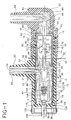
- Bushing 22 has a tubular metallic current -carrying element extending through bushing 22 to bore 12 in a direction perpendicular to axis 14.
- the portion of housing 10 disposed between tapered bushing 20 and operating end 18 has a generally cylindrical exterior surface, so that the wall of the housing in this region is generally in the form of a cylindrical tube.
- Housing 10 further includes a diaphragm 26 formed integrally with the other portions of the housing.
- Diaphragm 26 has a peripheral portion joining the tubular wall of the housing, a central portion 30 adjacent the axis 14 of the housing and annular convolutions 28 between the peripheral and central portions.
- the central portion 30 is free to move relative to the remainder of the housing upon flexure of convolutions 28.
- Diaphragm 26 is thick enough to provide full voltage withstand capability. That is, the thickness of diaphragm 26 is selected so that the diaphragm will withstand the maximum voltage to be imposed between the current-carrying elements of the switch and ground during service or during fault conditions. For example, in a switch designed to operate at a nominal 25 KV phase-to-phase the diaphragm and other parts intended to provide full voltage withstand capability should be capable of withstanding at least about 14.4 KV continuously.
- the housing is provided with an electrically conductive insert 32 formed from a mixture of the same elastomer used for the remainder of the housing and an electrically conductive material such as carbon black.
- Insert 32 covers the interior wall of bore 12 from diaphragm 26 to a point beyond bore 24. Insert 32 further extend radially inwardly for a short distance along the interior surface of diaphragm 26.
- the insert also has a short tubular section 33 extending along the exterior of the current-carrying element 58.
- Exterior support 42 is in intimate, void-free contact with the outside of housing 10, and is securely bonded to the dielectric elastomer of the housing.
- the semiconducting lining 32 is intimately bonded to the dielectric elastomer.
- Reinforcing element 36 is in intimate, void-free contact with insert 32 over one portion of its length, adjacent operating end 18 and with the dielectric elastomer of the housing over the remainder of its length.
- reinforcing element 36 is placed on an internal mandrel commonly referred to as a core.
- the core and reinforcing element are disposed within a mold cavity.
- the core has a face with grooves corresponding to convolutions 28.
- a further core extends through hole 37 in the reinforcing element.
- a mixture of elastomer and carbon is injected into the mold around the reinforcing element and cores and cured under heat and pressure to form the insert.
- the assembly is then transferred to different mold having the shape of the housing 10.
- the exterior support element is also disposed within the mold, so that the insert, reinforcing element and core contained therein are disposed within the exterior support element.
- Current-carrying element 58 is also positioned in the mold.
- the switch further includes an operating end buttress 46.
- the operating end buttress is formed from a metallic, electrically conductive material, preferably copper or a copper alloy.
- the operating end buttress has a first face 48 facing towards the operating end of the device and engaged with the shoulder 38 of the reinforcing element.
- the operating end buttress also has a second face 50 facing towards fixed end 16.
- a bore 52 extends through the operating end buttress and is substantially coaxial with axis 14 of the housing and reinforcing element. Bore 52 has an enlarged section 54.
- the operating end buttress also has a threaded fitting 56.
- a bolt 57 is disposed within current carrying element 58 and engages the threaded fitting 56. As further discussed below, the operating end buttress serves as a terminal for passage of current through the switch. The bolt 57 serves to maintain electrical continuity between the current carrying element 58 and buttress 46.
- a contact assembly 60 is disposed between the operating end buttress 46 and the fixed end 16 of the device.
- Contact assembly 60 includes a tubular ceramic bottle 62 with a metallic fixed end closure 64 disposed at one end of the bottle and a further, operating end closure 66 disposed at the opposite, operating end of the bottle.
- Operating end closure 66 includes a flexible, extensible metallic bellows.
- a fixed contact 68 is mounted to the fixed end closure 64 and projects into bottle 62, whereas a moveable or operating-end contact 70 is mounted to the bellows of the operating end closure 66.
- the assembly further includes a rod-like operating element 72 disposed on the outside of bellows 66 which forms an extension of the moveable contact.
- a threaded fixed end stub contact 74 is formed integrally with the fixed end contact 68 and projects outwardly beyond the fixed end closure 64.
- the contact assembly 60 further includes a metallic shield 76 surrounding portions of the contacts, the shield being supported within the housing by a metallic frame 78 extending through bottle 62.
- bottle 62 may be formed in sections, and both sections may be joined to the metallic frame.
- Bottle 62 is hermetically sealed. Thus, the joint between the end closures, contacts and bottle are gas-tight.
- controlled atmosphere means an atmosphere other than air at normal atmospheric pressure. Most preferably, the atmosphere within bottle 62 is under a subatmospheric pressure. The composition of the atmosphere may also differ from normal air. Arc-suppressing gases such as SF 6 may be present within the bottle.
- the entire contact assembly 60 may be a conventional, controlled-atmosphere ccntact assembly of the type commercially available from numerous sources. One such contact assembly is available under the designation Wt-35590 from the Cutler-Hammer Company of Horseheads, New York.
- the exterior diameter of bottle 62 is slightly less than the interior diameter of reinforcing element 36, so that there is an annular space between the outside of the bottle and the inside of the reinforcing element.
- This annular space is completely filled with a dielectric filler material 80, so as to provide a substantially void-free interface between the outside of the bottle and the inside of the reinforcing element.
- Filler 80 is formed from a dielectric material different from the dielectric material of housing 10. Most preferably, the dielectric filler 80 is a material which can be placed and brought to its final form without application of extreme temperatures or pressures. In service, the dielectric filler is not exposed to substantial mechanical stress. Therefore, the filler can be selected substantially without regard for its ability to withstand mechanical stress, abrasion and the like.
- the filler should have good dielectric strength.
- Preferred fillers include greases such as petroleum-based and silicone-based greases, gels such as silicone gels and curable elastomers of the type commonly referred to as room-temperature vulcanizing or "RTV" elastomers.
- Compatibility between the filler and the rubber of housing 10 should also be considered. Petroleum-based materials tend to swell EDPM. Therefore, if a petroleum-based filler is employed with an EPDM housing, the filler should be isolated from the housing during service. The dielectric reinforcing element can provide such isolation. Similarly, a silicone-based filler would tend to swell silicone rubber.
- the filler can also be made by deliberately swelling a rubber or other polymer.
- the space between the outside of bottle 62 and the inside of reinforcing element 36 can be loosely packed with a swellable polymer, such as EPDM or silicone rubber.
- the loose packing may be provided as a solid tube or mass; as granules or pellets; or in any other form such as a foam or sponge.
- a liquid capable of swelling the particular polymer used such as mineral oil (petroleum oil) in the case of EPDM or silicone oil in the case of silicone rubber, is then introduced into the space. The liquid causes the polymer to swell and fill the entire space, thereby providing a void-free interface. This technique can be applied to voids in other electrical assemblies as well.
- the switch further includes a fixed end cover 90 formed from a dielectric elastomer and a fixed end electrical stress relief element 92 formed from a semiconducting elastomer.
- the fixed end cover 90 is positioned on housing 10 so that an internal taper in the fixed end cover is firmly engaged with conical seat 20 at the fixed end of the housing and so that the fixed end electrical stress release element surrounds second terminal 88, stub terminal 74, fixed end buttress 40 and the fixed end closure 64 of the contact assembly.
- the fixed end cap has a second tubular metallic current carrying element 94 mounted therein. A bolt 95 disposed in the current-carrying element is threadedly engaged with the second terminal 88.
- a link 98 is slidably received in bore 52 of the operating end buttress 46.
- Link 98 is threadedly engaged with the operating element 72 of the contact assembly, and the threaded connection is locked against movement during service, as by a pin (not shown) extending through the threadedly engaged elements.
- An annular contact 100 of the type commonly referred to as a "louvered" contact, encircles link 98.
- Contact 100 has projections on its interior and exterior surfaces. The flexible projections on contact 100 bear on buttress 46 and on the link, thereby establishing a slidable electrical connection between the buttress and the link.
- the moveable contact 70 of the contact assembly is electrically connected to the first terminal or buttress 46.
- a flexible metallic strap such as a braided copper strap, can be connected between link 98 and the first end buttress or first terminal 46.
- a yoke 102 is slidably engaged with link 98.
- a coil compression spring 104 is disposed between yoke 102 and the end of link 98, so that motion of the yoke in the closing direction, towards fixed end 16, to the right in Fig. 1, will be transmitted to link 98 and hence to moveable contact 70 by a spring.
- a bolt 106 is engaged with the link and the yoke so that motion of the yoke in the opposite, opening direction (to the length in Fig. 1) will be transmitted to link 98 and to the moveable contact 70 through bolt 106.
- Bolt 106 desirably applies a preload to spring 104, so that the spring remains in compression at all times.
- actuating element 108 formed from a strong, rigid dielectric material such as epoxy-reinforced fiberglass extends through diaphragm 26 at the center 30 thereof.
- Actuating element 108 is fixedly attached and bonded to the center of diaphragm 30.
- actuating element 108 may be insert-molded into the diaphragm, by positioning the actuating element in the mold when the diaphragm is formed, during the aforementioned insert-molding process with a chemical bonding agent on the actuating element surface.
- Chemical bonding agents are well-known in the art of rubber molding.
- One suitable chemical bonding agent is sold under the registered trademark Chemlok 205.
- Chemlok 205 One suitable chemical bonding agent is sold under the registered trademark Chemlok 205.
- the actuating element itself, and the joint between the actuating element and the diaphragm should each have full voltage withstand capabilities.
- the actuating element may be assembled to the diaphragm. This may be accomplished by molding the diaphragm with a hole smaller than the diameter of the actuating element, and then press-fitting the actuating element into the hole so as to form an intimate bond between the surface of the actuating element and the surrounding portions of the diaphragm.
- the actuating element may be provided with a shoulder on one side of the diaphragm and a fastener such as a nut and washer on the other side of the diaphragm. The fastener and the shoulder hold the central portion of the diaphragm in compression and hold the actuating element in fixed position relative to the diaphragm. Such a compression joint establishes a fixed, secure interface between the actuating element and the diaphragm.
- Actuating element 108 is connected to yoke 102 by a snap-engageable connection.
- yoke 102 has a hole in the end of the yoke closest to the operating end of the device, and a groove 110 in the wall of such hole.
- Actuating element 108 has a circumferential groove 112 extending around it.
- a resilient snap ring 114 is engaged in these grooves so as to connect the actuating element to the link for movement therewith in endwise directions.
- An actuator or driver assembly 120 in accordance with one embodiment of the present invention is attached to the other elements of the switch.
- the actuator 120 includes a driver frame 122 mounted to the housing 10 of the switch; a mobile element 124 connected to the actuating element 108 and a mechanism 126 for moving the mobile element in the opening and closing directions to move the actuating element and thereby move the mobile contact 70 (Fig. 1), thus opening and closing the switch.
- Driver frame 124 may be formed from stainless steel or other suitable corrosion resistant metal or other material.
- the driver frame has an annular collar 128 formed at a forward end and a further collar 129. Collar 128 is sized so that it fits within the tubular external support element 42 (Fig.1). Machine screws 130 hold the collar 128 and hence driver frame 122 in assembled position relative to the external support element and thus relative to the elastomeric housing 10.
- a further cylindrical housing 131 (Fig. 2) fits over collar 129 and covers the mechanism of the driver. Only small portions of housing 131 are depicted in Figure 2; the remainder is removed for clarity of illustration. Further, cover 131 is omitted in Figs. 3-6.
- the driver frame 122 and collar 128 are disposed adjacent the operating end 18 of housing 10.
- the outer end of actuating element 108 extends though the collar assembly 128 into the driver frame 122, where the actuating element is connected to the mobile element 124 of the driver assembly by an adjustable connection such as a threaded connection, provided with a pin or other suitable locking device for locking the adjustment.
- Driver frame 122 includes a pair of plates 130 and 132 (Fig. 2).
- a pair of bellcrank elements 134a and 134b are mounted on a bellcrank shaft 138 extending between plates 130, so that the bellcrank elements are pivotable relative to the frame about a bellcrank axis coincident with shaft 138.
- Bellcrank elements 138 are rigidly connected to one another by a plate 139 extending therebetween.
- An opening side pin 135 and a closing side pin 137 extend between the bellcrank elements 134 adjacent the forward end of the mechanism on opposite sides.
- pins 135 and 137 form attachment points for connecting springs to the bellcrank.
- each bellcrank element has a generally arcuate surface with a notch 140 therein.
- An operating shaft 142 extends through plates 130 and 132 in bearings (not shown), so that the operating shaft is rotatable with respect to the driver frame.
- Operating shaft 142 has a polygonal head 144 on one end for engagement by an operating handle 145.
- a pair of cam plates 146 are fixedly mounted to operating shaft 142.
- the cam plates 146 cooperatively constitute a rocker.
- the rocker is mounted by shaft 142 for pivoting movement with respect to frame 122 about a rocker axis coincident with shaft 142.
- Rocker axis 142 is disposed rearwardly of bellcrank axis 138 but parallel thereto, so that the axes cooperatively define a common plane coincident with the central axis 14 of the switch.
- the region on one side of this plane (above the plane and above axis 14 in each of Figs. 2-6) is referred to as lying on the opening side of the plane, whereas the region on the opposite side, below the plane and axis 14 as seen in Figs. 2-6, is said to lie on the closing side of the plane.
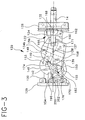
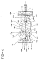
- Each cam plate of the rocker has a pair of main projections 148 and 150 (Fig. 4)extending in the forward direction, toward collar 128 and a pair of catch surfaces 152 and 154 (Figs. 3 and 4) extending in the rearward direction.
- the opening side projections 148 of cam plates 146 extend between bellcrank elements 134 when the mechanism is in the closed position illustrated in Figs. 2 and 3.
- Closing side projections 150 similarly extend between the bellcrank elements when the mechanism is in the open position illustrated in Fig. 5.
- An opening side pin or attachment point 153 extends between cam plates 146 of the rocker on the opening side of common plane 14, adjacent the opening side projections of the plates.
- a closing side pin or attachment points 155 extends between the cam plates of rocker 146 adjacent the closing side projections 150.
- opening side main spring 156 extends between the opening side pin 135 of the bellcranks and opening side pin 153 of cam 146.
- opening side spring 156 is a large, powerful spring which substantially occupies the space between the bellcrank elements and the space between the projections of the cam plates.
- the loops of spring 156 which are engaged with the pins have inside dimensions considerably larger than the pins themselves.
- a similar closing side spring 158 extends between the closing side pin 154 the closing side pin 155 of cam 146 and the closing side pin 137 of the bellcrank.
- closing spring 158 is depicted only schematically in Figures 3-6, it should be appreciated that the closing side spring is also a massive, powerful spring which occupies much of the space between the bellcrank elements and between the closing side projections 150 of the cam plates.
- a pair of guide link plates 160 are pivotally mounted to the driver frame adjacent plates 130 and 132 on pins 162 (Figs. 3 and 4).
- a pair of drive link plates 166 extend adjacent frame plates 130 and 132.
- a main pin 168 connects the guide link plates 162 to the drive link plates 166, and also connects the link plates to the mobile element 124 of the drive mechanism.
- Drive link plates 166 are connected by further pins 171 to the bellcrank elements.
- the driver frame 122, guide links 162, drive links 166 and bellcrank elements 134 constitute a mechanism of the type commonly referred to as a "four bar" linkage.
- Opening catch 170 (Figs. 3 and 4) is rotatably mounted on operating shaft 142. Opening catch 170 is disposed in a space 173 adjacent cam plate 146 and bellcrank plate 146b, on one side of the mechanism. Catch 172 is omitted for clarity of illustration in Fig. 2 and in Figs. 5 and 6. Opening catch 170 has a roller-equipped tip 174. The opening catch 170 also has a finger 176 and a spring mount 178. A catch spring 182 is engaged between the spring mount 178 and the cap 129 of the driver frame. Spring 182 biases opening catch 170 in the clockwise direction as seen in Figs. 3 and 4, and thus biases the tip 174 of the catch into engagement with the arcuate surface of bellcrank element 134b.
- a similar closing catch 186 (Figs. 5 and 6) is rotatably mounted to the operating shaft 142 in space 188 (Fig. 2) adjacent bellcrank element 134a.
- Closing catch 186 is omitted for clarity of illustration in Figure 2 and Figures 3 and 4.
- Closing catch 186 has a roller equipped tip 190, spring arm 192 and finger 194 similar to the corresponding elements of the opening catch.
- Catch spring 196 is engaged between spring arm 192 of the closing catch and cap 129 of the frame so as to bias the closing catch in the counterclockwise direction about shaft 142 and thus bias the tip 190 into engagement with bellcrank plate 134a.
- a flipper plate 196 having a pair of projections 198a and 198b (Fig.
- the switch is connected in the circuit through current-carrying elements 58 and 94, and hence through terminals 46 and 88.
- Insert 32 is electrically connected to the first terminal 46.
- Link 98 and yoke 102 are at the same potential, and hence there is no potential gradient within the space enclosed by insert 32.
- Stress relief element 92 likewise maintains all of the components at the fixed end of the switch at the potential of second terminal 88
- the opening spring 156 is stretched between pins 153 and 135, whereas closing spring 158 is relaxed.
- the mechanism reaches the opening unlatch position illustrated in Fig. 4. In this position, the closing side projections 150 of the cam plates are engaged between the bellcrank elements 134.
- the cam plates and the bellcrank elements form a substantially continuous channel, with walls bounding the closing spring 158 on opposite sides thereof.
- catch surface 154 does not engage the flipper plate, and the flipper plate does not engage finger 176 until cams 146 are almost at the end of their counterclockwise rotary movement.
- the entire action of lifting the roller tip 174 out of slot 140 occurs over a very short rotational movement of rocker 146, between the opening start position and the opening unlatch position.
- opening spring 156 drives the bell crank 134 in rotation in a closing direction, counterclockwise as seen in Figs. 3 and 4, until the bellcrank elements reach the position illustrated in Fig. 5.
- the components are dimensioned so that the opening spring remains under tension throughout the opening motion of the bellcrank.
- the rearward motion or opening throw of the opening-side attachment pin 153 on the rocker from the fully closed position of Fig. 3 to the fully-open position of Fig. 5, is greater than the rearward motion or opening stroke of the opening-side attachment pin 135 on the bellcrank.
- the forward motion of the closing-side pin 154 of the rocker is greater than the forward motion of the corresponding pin 137 of the bellcrank.
- the closing-side spring is brought to a slack condition and remains slack when the bellcrank reaches the open position illustrated in Fig. 5. Any excess motion of pin 154 beyond that required to bring the closing-side spring to a fully slack condition is taken up by movement of the pin within the end loop of the spring; the closing-side spring is not placed in compression. The continued presence of tension in the opening-side spring throughout the opening motion helps to assure that the mechanism does not stall at some intermediate position during the opening stroke.
- the end loops and pins serve as a lost-motion linkage connected in series with opening-side spring 156 between the opening-side attachment points of the bellcrank and rocker and a further lost-motion linkage connected in series with the closing-side spring 158 between the closing-side attachment points of the bellcrank and rocker.
- closing spring 158 pulls the closing side attachment pin 137 of the bellcrank rearwardly, and thus drives the bellcrank 134a in rotation in a closing direction, clockwise as seen in the drawings, until the bellcrank reaches the closed position illustrated in Fig. 3.
- the closing-side spring remains under tension throughout the closing cycle, and remains under tension when the bellcrank reaches the closed position. To provide such tension, the rearward movement or throw of the closing-side attachment point 154 on the rocker is greater than the rearward movement or stroke of the closing-side attachment point 137 on the rocker.
- cam plate 40 The closing rotation of cam plate 40 is arrested by stops 202 and the flipper plate 196.
- the closing movement of the bell cranks(from the position of Fig. 6 to the position of Fig. 3) brings pins 171 into alignment with pins 138 and 168.
- the linkage provides a substantial mechanical advantage so that the mobile element 124 is driven in the closing direction with substantial force.
- the connection between mobile element 124 and actuating element 108 is adjusted so that movable contact 70 engages fixed contact 68 slightly before closing movement of the driver mechanism is completed.
- the final motion of the driver mechanism, after contact engagement, is accommodated by sliding movement of yoke 102 (Fig. 1) relative to link 98, against the bias of spring 104. This movement minimizes mechanical shock loading applied to the contacts.
- the loads which are applied to the contact assembly during closing motion are transmitted through fixed contact 68, end closure 64 and fixed end buttress 82 to reinforcing element 36 via threaded connection 40. Essentially none of these loads are applied to bottle 62.
- the loads applied to reinforcing element 36 tend to move it in the closing direction (to the right in Fig. 1) relative to the driver frame.
- exterior reinforcing element 42 is fixed to the driver frame by collar 128.
- the exterior reinforcing element restrains housing 10, which in turn restrains the reinforcing element.
- the interior and exterior reinforcing elements 36 and 42 are telescoped together, and engage housing 10 over large surface areas, with only a thin annular portion of the elastomer of the housing interposed between them. This forms a rigid, stress-resistant joint which firmly supports the reinforcing element 36 against motion.
- the driver mechanism or actuator discussed above provides significant advantages. It moves the contact rapidly between opened and closed positions so as to minimize arcing.
- the driver mechanism is extremely compact. The entire mechanism is accommodated in a tubular housing of essentially the same diameter as the switch exterior reinforcing element.
- An O-ring or other conventional seals can be provided between driver tubular housing 131, collars 128 and 129 and so as to provide a weather- tight seal protecting the elements of the driver mechanism.
- the driver housing 131 is also provided with a hole (not shown) for passage of the handle 145. This hole may be provided with appropriate seals.
- the actuator can be made in essentially any size, to fit any high-voltage switch
- one useful actuator has opening and closing main springs with spring constants of about 160 lb/in or 175.2N/m, and has a bellcrank with a moment of inertia about the bellcrank axis of about 3.3 lb-in 2 or .0009 Kg-m 2 .
- Each main spring is stretched by about 0.97 in or 25 mm during movement of the rocker to the opening-unlatch or closing-unlatch position.
- the distance between the bellcrank axis and the rocker axis is about 2 in or 51mm, whereas the radial distance from the rocker axis 142 to each of the opening-side and closing side attach pins 153 and 154 is about 1.39 in or 35mm.
- the radial distance from the bellcrank axis 138 to each of the opening-side and closing-side attach pins 135 and 137 is about 1.57 in or 40mm.
Landscapes
- Mechanisms For Operating Contacts (AREA)
- Switch Cases, Indication, And Locking (AREA)
- High-Tension Arc-Extinguishing Switches Without Spraying Means (AREA)
- Push-Button Switches (AREA)
- Arc-Extinguishing Devices That Are Switches (AREA)
- Lock And Its Accessories (AREA)
Applications Claiming Priority (2)
| Application Number | Priority Date | Filing Date | Title |
|---|---|---|---|
| US578040 | 1995-12-26 | ||
| US08/578,040 US5717185A (en) | 1995-12-26 | 1995-12-26 | Operating mechanism for high voltage switch |
Publications (3)
| Publication Number | Publication Date |
|---|---|
| EP0782161A2 true EP0782161A2 (fr) | 1997-07-02 |
| EP0782161A3 EP0782161A3 (fr) | 1998-10-28 |
| EP0782161B1 EP0782161B1 (fr) | 2002-03-27 |
Family
ID=24311200
Family Applications (1)
| Application Number | Title | Priority Date | Filing Date |
|---|---|---|---|
| EP96309461A Expired - Lifetime EP0782161B1 (fr) | 1995-12-26 | 1996-12-23 | Dispositif d'actionnement d'interrupteur |
Country Status (10)
| Country | Link |
|---|---|
| US (1) | US5717185A (fr) |
| EP (1) | EP0782161B1 (fr) |
| JP (1) | JP3038159B2 (fr) |
| KR (2) | KR970051596A (fr) |
| CN (1) | CN1071927C (fr) |
| AU (1) | AU683279B2 (fr) |
| BR (1) | BR9606160B1 (fr) |
| CA (1) | CA2192136C (fr) |
| DE (1) | DE69620131T2 (fr) |
| TW (1) | TW373205B (fr) |
Cited By (2)
| Publication number | Priority date | Publication date | Assignee | Title |
|---|---|---|---|---|
| EP3826045A1 (fr) * | 2005-08-22 | 2021-05-26 | ABB Schweiz AG | Procédé de fabrication de pièces de pôle d'interrupteur pour installation de moyenne et haute tension |
| EP4542605A1 (fr) * | 2023-10-18 | 2025-04-23 | ABB Schweiz AG | Disjoncteur à vide |
Families Citing this family (36)
| Publication number | Priority date | Publication date | Assignee | Title |
|---|---|---|---|---|
| JP2004220999A (ja) * | 2003-01-17 | 2004-08-05 | Mitsubishi Electric Corp | 密閉型開閉装置 |
| US7341468B2 (en) | 2005-07-29 | 2008-03-11 | Cooper Technologies Company | Separable loadbreak connector and system with shock absorbent fault closure stop |
| US7384287B2 (en) * | 2005-08-08 | 2008-06-10 | Cooper Technologies Company | Apparatus, system and methods for deadfront visible loadbreak |
| US7772515B2 (en) * | 2005-11-14 | 2010-08-10 | Cooper Technologies Company | Vacuum switchgear assembly and system |
| US7488916B2 (en) * | 2005-11-14 | 2009-02-10 | Cooper Technologies Company | Vacuum switchgear assembly, system and method |
| US7572133B2 (en) * | 2005-11-14 | 2009-08-11 | Cooper Technologies Company | Separable loadbreak connector and system |
| US20080192409A1 (en) * | 2007-02-13 | 2008-08-14 | Paul Michael Roscizewski | Livebreak fuse removal assembly for deadfront electrical apparatus |
| US7854620B2 (en) * | 2007-02-20 | 2010-12-21 | Cooper Technologies Company | Shield housing for a separable connector |
| US20090100675A1 (en) * | 2007-02-20 | 2009-04-23 | Cooper Technologies Company | Method for manufacturing a shield housing for a separable connector |
| US7494355B2 (en) * | 2007-02-20 | 2009-02-24 | Cooper Technologies Company | Thermoplastic interface and shield assembly for separable insulated connector system |
| US7950939B2 (en) * | 2007-02-22 | 2011-05-31 | Cooper Technologies Company | Medium voltage separable insulated energized break connector |
| US7666012B2 (en) * | 2007-03-20 | 2010-02-23 | Cooper Technologies Company | Separable loadbreak connector for making or breaking an energized connection in a power distribution network |
| US7568927B2 (en) * | 2007-04-23 | 2009-08-04 | Cooper Technologies Company | Separable insulated connector system |
| US7633741B2 (en) * | 2007-04-23 | 2009-12-15 | Cooper Technologies Company | Switchgear bus support system and method |
| US7661979B2 (en) | 2007-06-01 | 2010-02-16 | Cooper Technologies Company | Jacket sleeve with grippable tabs for a cable connector |
| US8450630B2 (en) * | 2007-06-05 | 2013-05-28 | Cooper Technologies Company | Contact backing for a vacuum interrupter |
| US7781694B2 (en) * | 2007-06-05 | 2010-08-24 | Cooper Technologies Company | Vacuum fault interrupter |
| US7695291B2 (en) | 2007-10-31 | 2010-04-13 | Cooper Technologies Company | Fully insulated fuse test and ground device |
| US8056226B2 (en) | 2008-02-25 | 2011-11-15 | Cooper Technologies Company | Method of manufacturing a dual interface separable insulated connector with overmolded faraday cage |
| US7670162B2 (en) | 2008-02-25 | 2010-03-02 | Cooper Technologies Company | Separable connector with interface undercut |
| US7578682B1 (en) | 2008-02-25 | 2009-08-25 | Cooper Technologies Company | Dual interface separable insulated connector with overmolded faraday cage |
| US7950940B2 (en) * | 2008-02-25 | 2011-05-31 | Cooper Technologies Company | Separable connector with reduced surface contact |
| US7905735B2 (en) * | 2008-02-25 | 2011-03-15 | Cooper Technologies Company | Push-then-pull operation of a separable connector system |
| US8109776B2 (en) | 2008-02-27 | 2012-02-07 | Cooper Technologies Company | Two-material separable insulated connector |
| US7811113B2 (en) * | 2008-03-12 | 2010-10-12 | Cooper Technologies Company | Electrical connector with fault closure lockout |
| US7958631B2 (en) * | 2008-04-11 | 2011-06-14 | Cooper Technologies Company | Method of using an extender for a separable insulated connector |
| US7878849B2 (en) * | 2008-04-11 | 2011-02-01 | Cooper Technologies Company | Extender for a separable insulated connector |
| US8002565B2 (en) | 2009-01-22 | 2011-08-23 | Integro, Llc | Waterproof connector kit useful for airfield lighting applications |
| CN101494133B (zh) * | 2009-02-25 | 2011-08-24 | 谢翠斌 | 高压真空永磁断路器手动合闸、分闸及其锁扣保护装置 |
| US8674254B2 (en) | 2011-01-31 | 2014-03-18 | Thomas & Betts International, Inc. | Flexible seal for high voltage switch |
| USD703622S1 (en) * | 2012-03-23 | 2014-04-29 | Mitsubishi Electric Corporation | Shield for vacuum circuit breaker |
| USD709462S1 (en) * | 2012-03-23 | 2014-07-22 | Mitsubishi Electric Corporation | Case for vacuum circuit breaker |
| DE102014210587A1 (de) * | 2014-06-04 | 2015-12-17 | Siemens Aktiengesellschaft | Verfahren zur Herstellung eines feststoffisolierten Schalterpols und feststoffisolierter Schalterpol |
| USD907594S1 (en) * | 2019-06-06 | 2021-01-12 | Ningbo C.F Electronic Tech Co., Ltd | Electrolyzer |
| CN111632779B (zh) * | 2020-05-21 | 2023-03-24 | 国网宁夏电力有限公司检修公司 | 一种用于高压隔离开关的导电液喷涂装置 |
| CN113793770A (zh) * | 2021-10-13 | 2021-12-14 | 广东俊朗松田电器有限公司 | 一种双重驱动的开关 |
Citations (5)
| Publication number | Priority date | Publication date | Assignee | Title |
|---|---|---|---|---|
| US2870298A (en) | 1956-08-27 | 1959-01-20 | Schwager Wood Corp | Encapsulated vacuum insulated circuit breaker |
| US3471669A (en) | 1968-01-16 | 1969-10-07 | Chance Co Ab | Encapsulated switch assembly for underground electric distribution service |
| US3812314A (en) | 1971-08-23 | 1974-05-21 | Gen Electric | High power electrical bushing having a vacuum switch encapsulated therein |
| US3955167A (en) | 1975-01-08 | 1976-05-04 | Mcgraw-Edison Company | Encapsulated vacuum fuse assembly |
| US4568804A (en) | 1983-09-06 | 1986-02-04 | Joslyn Mfg. And Supply Co. | High voltage vacuum type circuit interrupter |
Family Cites Families (20)
| Publication number | Priority date | Publication date | Assignee | Title |
|---|---|---|---|---|
| US2744984A (en) * | 1953-08-12 | 1956-05-08 | Cutler Hammer Inc | Sealing means for lever operated electric switches |
| CA603843A (en) * | 1955-03-29 | 1960-08-23 | Chester W. Upton, Jr. | Sealed device |
| US2794101A (en) * | 1955-08-29 | 1957-05-28 | Jennings Radio Mfg Corp | Vacuum switch |
| US2995639A (en) * | 1956-11-02 | 1961-08-08 | Panerai Giuseppe | Device for controlling from outside the members contained within a hermetically sealed box, apt to be immersed into a pressurized ambient |
| US3244015A (en) * | 1964-07-10 | 1966-04-05 | Square D Co | Switch operating mechanism |
| US3597713A (en) * | 1969-01-03 | 1971-08-03 | Esco Mfg Co | Current responsive circuit breaker with releasable coupling means, and with circuitry means disposed within a hollow terminal |
| US3787649A (en) * | 1972-08-04 | 1974-01-22 | Allis Chalmers | Vacuum switch cam operating mechanism with contact loading compression spring |
| US3941957A (en) * | 1974-05-09 | 1976-03-02 | Tilman Ted N | High current high voltage switch structure with conductive piston |
| US4168414A (en) * | 1975-03-06 | 1979-09-18 | Mcgraw-Edison Company | Protective switch device and operating mechanism therefor |
| US4124790A (en) * | 1975-03-06 | 1978-11-07 | Mcgraw-Edison Company | Protective switch device and operating mechanism therefor |
| DE2717958B2 (de) * | 1977-04-20 | 1979-06-13 | Siemens Ag, 1000 Berlin Und 8000 Muenchen | Antriebsvorrichtung für elektrische Schaltgeräte mit Druckkontakten |
| US4215253A (en) * | 1978-12-28 | 1980-07-29 | Tilman Ted N | High direct and alternating current switch |
| US4283610A (en) * | 1979-03-09 | 1981-08-11 | Mcgraw-Edison Company | Operator for a circuit interrupter and disconnect switch combination |
| US4230922A (en) * | 1979-04-30 | 1980-10-28 | Cherry Electrical Products Corp. | Seal assembly for switch actuator |
| US4419553A (en) * | 1981-01-19 | 1983-12-06 | Mitsubishi Denki Kabushiki Kaisha | Vacuum type circuit breaker |
| US4709126A (en) * | 1986-10-02 | 1987-11-24 | Furnas Electric Company | Pressure switch with rolling diaphragm |
| JPS6429726U (fr) * | 1987-08-14 | 1989-02-22 | ||
| US4894497A (en) * | 1989-02-08 | 1990-01-16 | Service Machine Company | High temperature pressure switch assembly for use with explosion-proof enclosures |
| JP2520963Y2 (ja) * | 1990-10-31 | 1996-12-18 | 矢崎総業株式会社 | 圧力スイッチ |
| US5508487A (en) * | 1994-03-30 | 1996-04-16 | Abb Power T&D Company Inc. | High voltage circuit interrupting device operating mechanism including trip latch assembly |
-
1995
- 1995-12-26 US US08/578,040 patent/US5717185A/en not_active Expired - Lifetime
-
1996
- 1996-11-21 AU AU71882/96A patent/AU683279B2/en not_active Expired
- 1996-12-05 CA CA002192136A patent/CA2192136C/fr not_active Expired - Lifetime
- 1996-12-10 TW TW085115273A patent/TW373205B/zh not_active IP Right Cessation
- 1996-12-17 JP JP8337270A patent/JP3038159B2/ja not_active Expired - Lifetime
- 1996-12-23 KR KR1019960070208A patent/KR970051596A/ko active Granted
- 1996-12-23 KR KR1019960070208A patent/KR100233727B1/ko not_active Expired - Lifetime
- 1996-12-23 EP EP96309461A patent/EP0782161B1/fr not_active Expired - Lifetime
- 1996-12-23 DE DE69620131T patent/DE69620131T2/de not_active Expired - Lifetime
- 1996-12-24 BR BRPI9606160-0A patent/BR9606160B1/pt not_active IP Right Cessation
- 1996-12-26 CN CN96114084A patent/CN1071927C/zh not_active Expired - Fee Related
Patent Citations (5)
| Publication number | Priority date | Publication date | Assignee | Title |
|---|---|---|---|---|
| US2870298A (en) | 1956-08-27 | 1959-01-20 | Schwager Wood Corp | Encapsulated vacuum insulated circuit breaker |
| US3471669A (en) | 1968-01-16 | 1969-10-07 | Chance Co Ab | Encapsulated switch assembly for underground electric distribution service |
| US3812314A (en) | 1971-08-23 | 1974-05-21 | Gen Electric | High power electrical bushing having a vacuum switch encapsulated therein |
| US3955167A (en) | 1975-01-08 | 1976-05-04 | Mcgraw-Edison Company | Encapsulated vacuum fuse assembly |
| US4568804A (en) | 1983-09-06 | 1986-02-04 | Joslyn Mfg. And Supply Co. | High voltage vacuum type circuit interrupter |
Cited By (2)
| Publication number | Priority date | Publication date | Assignee | Title |
|---|---|---|---|---|
| EP3826045A1 (fr) * | 2005-08-22 | 2021-05-26 | ABB Schweiz AG | Procédé de fabrication de pièces de pôle d'interrupteur pour installation de moyenne et haute tension |
| EP4542605A1 (fr) * | 2023-10-18 | 2025-04-23 | ABB Schweiz AG | Disjoncteur à vide |
Also Published As
| Publication number | Publication date |
|---|---|
| JP3038159B2 (ja) | 2000-05-08 |
| BR9606160B1 (pt) | 2008-11-18 |
| MX9606693A (es) | 1998-06-30 |
| BR9606160A (pt) | 1998-09-01 |
| CA2192136C (fr) | 2000-02-29 |
| EP0782161B1 (fr) | 2002-03-27 |
| DE69620131D1 (de) | 2002-05-02 |
| CN1071927C (zh) | 2001-09-26 |
| KR100233727B1 (ko) | 1999-12-01 |
| TW373205B (en) | 1999-11-01 |
| CN1156892A (zh) | 1997-08-13 |
| CA2192136A1 (fr) | 1997-06-27 |
| EP0782161A3 (fr) | 1998-10-28 |
| KR970051596A (ko) | 1997-07-29 |
| DE69620131T2 (de) | 2002-09-26 |
| US5717185A (en) | 1998-02-10 |
| AU683279B2 (en) | 1997-11-06 |
| JPH09190746A (ja) | 1997-07-22 |
| AU7188296A (en) | 1997-08-14 |
Similar Documents
| Publication | Publication Date | Title |
|---|---|---|
| EP0782161B1 (fr) | Dispositif d'actionnement d'interrupteur | |
| EP0782162B1 (fr) | Interrupteurs à haute tension | |
| US3471669A (en) | Encapsulated switch assembly for underground electric distribution service | |
| US7579572B2 (en) | High current switch and method of operation | |
| US7772515B2 (en) | Vacuum switchgear assembly and system | |
| US11600459B2 (en) | Single bottle interrupter | |
| US11095099B2 (en) | Gas-insulated switching device | |
| CZ288889B6 (cs) | Zátěžový vypínač | |
| MXPA96006693A (en) | Conmuta actuator | |
| MXPA96006696A (en) | High volt switches | |
| US11430622B2 (en) | Interrupter assembly | |
| CA2736031C (fr) | Interrupteur de courant de grande intensite et methode d'utilisation connexe | |
| JPH0644875A (ja) | 樹脂モールド真空バルブ | |
| WO1995027298A1 (fr) | Ensemble interrupteur |
Legal Events
| Date | Code | Title | Description |
|---|---|---|---|
| PUAI | Public reference made under article 153(3) epc to a published international application that has entered the european phase |
Free format text: ORIGINAL CODE: 0009012 |
|
| AK | Designated contracting states |
Kind code of ref document: A2 Designated state(s): BE DE FR GB IE IT NL SE |
|
| PUAL | Search report despatched |
Free format text: ORIGINAL CODE: 0009013 |
|
| AK | Designated contracting states |
Kind code of ref document: A3 Designated state(s): BE DE FR GB IE IT NL SE |
|
| RAP1 | Party data changed (applicant data changed or rights of an application transferred) |
Owner name: THOMAS & BETTS INTERNATIONAL, INC. |
|
| 17P | Request for examination filed |
Effective date: 19990416 |
|
| GRAG | Despatch of communication of intention to grant |
Free format text: ORIGINAL CODE: EPIDOS AGRA |
|
| 17Q | First examination report despatched |
Effective date: 20010212 |
|
| GRAG | Despatch of communication of intention to grant |
Free format text: ORIGINAL CODE: EPIDOS AGRA |
|
| GRAH | Despatch of communication of intention to grant a patent |
Free format text: ORIGINAL CODE: EPIDOS IGRA |
|
| GRAH | Despatch of communication of intention to grant a patent |
Free format text: ORIGINAL CODE: EPIDOS IGRA |
|
| RAP1 | Party data changed (applicant data changed or rights of an application transferred) |
Owner name: THOMAS & BETTS INTERNATIONAL, INC. |
|
| REG | Reference to a national code |
Ref country code: GB Ref legal event code: IF02 |
|
| GRAA | (expected) grant |
Free format text: ORIGINAL CODE: 0009210 |
|
| AK | Designated contracting states |
Kind code of ref document: B1 Designated state(s): BE DE FR GB IE IT NL SE |
|
| REF | Corresponds to: |
Ref document number: 69620131 Country of ref document: DE Date of ref document: 20020502 |
|
| REG | Reference to a national code |
Ref country code: IE Ref legal event code: FG4D |
|
| ET | Fr: translation filed | ||
| PLBE | No opposition filed within time limit |
Free format text: ORIGINAL CODE: 0009261 |
|
| STAA | Information on the status of an ep patent application or granted ep patent |
Free format text: STATUS: NO OPPOSITION FILED WITHIN TIME LIMIT |
|
| 26N | No opposition filed |
Effective date: 20021230 |
|
| PGFP | Annual fee paid to national office [announced via postgrant information from national office to epo] |
Ref country code: NL Payment date: 20090524 Year of fee payment: 13 Ref country code: IE Payment date: 20090527 Year of fee payment: 13 |
|
| PGFP | Annual fee paid to national office [announced via postgrant information from national office to epo] |
Ref country code: SE Payment date: 20090528 Year of fee payment: 13 Ref country code: IT Payment date: 20090528 Year of fee payment: 13 |
|
| PGFP | Annual fee paid to national office [announced via postgrant information from national office to epo] |
Ref country code: BE Payment date: 20090624 Year of fee payment: 13 |
|
| BERE | Be: lapsed |
Owner name: *THOMAS & BETTS INTERNATIONAL INC. Effective date: 20091231 |
|
| REG | Reference to a national code |
Ref country code: NL Ref legal event code: V1 Effective date: 20100701 |
|
| EUG | Se: european patent has lapsed | ||
| REG | Reference to a national code |
Ref country code: IE Ref legal event code: MM4A |
|
| PG25 | Lapsed in a contracting state [announced via postgrant information from national office to epo] |
Ref country code: NL Free format text: LAPSE BECAUSE OF NON-PAYMENT OF DUE FEES Effective date: 20100701 Ref country code: IE Free format text: LAPSE BECAUSE OF NON-PAYMENT OF DUE FEES Effective date: 20091223 Ref country code: BE Free format text: LAPSE BECAUSE OF NON-PAYMENT OF DUE FEES Effective date: 20091231 |
|
| PG25 | Lapsed in a contracting state [announced via postgrant information from national office to epo] |
Ref country code: IT Free format text: LAPSE BECAUSE OF NON-PAYMENT OF DUE FEES Effective date: 20091223 |
|
| PG25 | Lapsed in a contracting state [announced via postgrant information from national office to epo] |
Ref country code: SE Free format text: LAPSE BECAUSE OF NON-PAYMENT OF DUE FEES Effective date: 20091224 |
|
| REG | Reference to a national code |
Ref country code: FR Ref legal event code: PLFP Year of fee payment: 20 |
|
| PGFP | Annual fee paid to national office [announced via postgrant information from national office to epo] |
Ref country code: GB Payment date: 20151223 Year of fee payment: 20 Ref country code: DE Payment date: 20151215 Year of fee payment: 20 |
|
| PGFP | Annual fee paid to national office [announced via postgrant information from national office to epo] |
Ref country code: FR Payment date: 20151110 Year of fee payment: 20 |
|
| REG | Reference to a national code |
Ref country code: DE Ref legal event code: R071 Ref document number: 69620131 Country of ref document: DE |
|
| REG | Reference to a national code |
Ref country code: GB Ref legal event code: PE20 Expiry date: 20161222 |
|
| PG25 | Lapsed in a contracting state [announced via postgrant information from national office to epo] |
Ref country code: GB Free format text: LAPSE BECAUSE OF EXPIRATION OF PROTECTION Effective date: 20161222 |