EP0782231A1 - Zündspulenvorrichtung für Verbrennungsmotor - Google Patents
Zündspulenvorrichtung für Verbrennungsmotor Download PDFInfo
- Publication number
- EP0782231A1 EP0782231A1 EP96120612A EP96120612A EP0782231A1 EP 0782231 A1 EP0782231 A1 EP 0782231A1 EP 96120612 A EP96120612 A EP 96120612A EP 96120612 A EP96120612 A EP 96120612A EP 0782231 A1 EP0782231 A1 EP 0782231A1
- Authority
- EP
- European Patent Office
- Prior art keywords
- case
- coil
- voltage terminal
- coil device
- engine igniting
- Prior art date
- Legal status (The legal status is an assumption and is not a legal conclusion. Google has not performed a legal analysis and makes no representation as to the accuracy of the status listed.)
- Granted
Links
Images

Classifications
-
- F—MECHANICAL ENGINEERING; LIGHTING; HEATING; WEAPONS; BLASTING
- F02—COMBUSTION ENGINES; HOT-GAS OR COMBUSTION-PRODUCT ENGINE PLANTS
- F02P—IGNITION, OTHER THAN COMPRESSION IGNITION, FOR INTERNAL-COMBUSTION ENGINES; TESTING OF IGNITION TIMING IN COMPRESSION-IGNITION ENGINES
- F02P3/00—Other installations
- F02P3/02—Other installations having inductive energy storage, e.g. arrangements of induction coils
-
- H—ELECTRICITY
- H01—ELECTRIC ELEMENTS
- H01T—SPARK GAPS; OVERVOLTAGE ARRESTERS USING SPARK GAPS; SPARKING PLUGS; CORONA DEVICES; GENERATING IONS TO BE INTRODUCED INTO NON-ENCLOSED GASES
- H01T13/00—Sparking plugs
- H01T13/40—Sparking plugs structurally combined with other devices
- H01T13/44—Sparking plugs structurally combined with other devices with transformers, e.g. for high-frequency ignition
Definitions
- the present invention relates to an engine igniting coil device.
- Japanese Utility Model Publication No. 4-23296 discloses an open-magnetic-circuit-type engine igniting coil device which has a coil case which contains an assembly integrally molded therein by potting with melt insulating resin and consisting of a primary coil bobbin having a hollow shaft with a rod-shape core and a secondary coil bobbin coaxially laid on the primary coil bobbin and, which is further provided with an ignition-plug connector portion integrally formed on the coil case in such a way that a tip of an ignition plug inserted therein can be in contact with a high-voltage terminal inwardly projecting in the connector portion of the coil case.
- Japanese Laid-Open Patent No. 5-87034 also discloses an engine igniting coil device with an incorporated igniter, which comprises a single cylindrical coil case having an open top and a closed bottom, wherein a primary coil and secondary coil bobbin having a hollow shaft with a core inserted therein is mounted and integrally molded by potting with melt insulating resin and, then, an igniter with an attached thereto heat sink is mounted in an upper portion of the open top end of the coil case, leaving the heat sink exposed outside, and integrally molded therein by potting with melted resin.
- the first problem is that an inner assembly of a primary coil bobbin, a secondary coil bobbin, a rod type core and a high-voltage terminal socket may be displaced from a specified position in a coil case while melted resin is poured into the coil case. This results in that a tip of an ignition plug can not sufficiently fit in a high-voltage terminal socket integrally molded in the coil case.
- the assembly consisting of the primary coil bobbin, secondary coil bobbin, rod type core and high-voltage terminal socket must be fixed to the required position by using suitable additional means that may require additional parts and additional processing steps. Consequently, the efficiency of manufacturing the ignition coil device is decreased.
- the second problem is that the conventional open-magnetic-circuit type engine igniting coil device has a rod-shape core inserted in a hollow shaft of a bobbin with a primary coil and a secondary coil and, therefore, has a low output-efficiency because a produced magnetic flux can extend outwards and is reduced by iron loss while passing cylinder blocks of the engine. Consequently, the conventional device necessarily has an increased size to assure a specified secondary output voltage.
- the solidified resin layer between the coil case and the inner assembly may suffer thermal-stress cracking that allows current leakage resulting in impairing the resin quality.
- the third problem of the conventional device is that an igniter with a heat sink is potted only at its bottom and sides in resin layer in the open top end of a coil case may come out of the coil case.
- the igniter is mounted in the case independent of a low-voltage terminal socket integrally formed with the coil case. This requires separate step of wiring between the igniter and the low-voltage terminal, reducing the assembling work efficiency.
- the fourth problem is that a conventional engine igniting coil device with an ignition plug directly attached thereto is formed in a single piece and therefore must be prepared in different sizes depending upon kinds of engines that have different sizes between a mounting seat of an ignition coil device and an ignition plug.
- an engine igniting coil device which comprises a coil case composed of a first cylindrical case and a second cylindrical case having a small tubular hole in its center portion and fitted at its open end into an open end of the first case to form a closed end of the coil case and an inner assembly consisting of a primary coil bobbin, a secondary coil bobbin having a high-voltage terminal holder projecting in a center of its end flange portion, a rod-shape core and a high-voltage terminal attached to the high-voltage terminal holder and having a contact for electrically connecting an ignition plug thereto and which coil case with the internal assembly mounted therein with the high-voltage terminal holder press-fitted in the small tubular hole of the secondary case to project a tip of the contact outside therefrom is potted with melted insulating resin injected through an open-end of the coil case to form a single solid device, thus the inner assembly can be easily fixed at a given place in the
- Another object of the present invention is to provide an open-magnetic-circuit type engine igniting coil device which comprises a coil case, an assembly of a primary coil bobbin and a secondary coil bobbin with a hollow shaft having an inserted therein rod-shape core and which is featured in that the case body for accommodating therein the inner assembly is a cylinder made of metal having a high magnetic permeability, which cylinder has a longitudinal gap-forming slit and is covered internally with an elastic member, and a resin layer is formed between the covering member and the assembly, thus improving an output efficiency and prevent thermal-stress cracking from being formed in the solidified resin-layer.
- Another object of the present invention is to provide an engine igniting coil device including an igniter, which is reliable and easy to assemble, wherein a low-voltage terminal-socket holder is inserted into an open end of a coil case for communication with the internal assembly mounted therein and an igniter is mounted with a heat sink up in the socket holder, then the holder is potted with melted resin to the level at which the igniter and the heat sink are immersed and is covered with a cap whose internal rib is also immersed in the melted resin to form a single solid body.
- Another object of the present invention is to provide an engine igniting coil device including an igniter, which has a three-piece coil-case composed of a first cylindrical case for accommodating therein an ignition coil assembly, a second case fitted in the open bottom end of the first case and a low-voltage terminal socket portion fitted in the open top end of the first case, thus allowing exchanging the second case or the socket portion for another one of different size in accordance with another engine having a different mounting size for the ignition coil.
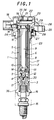
- Fig. 1 is a sectional front view of an engine igniting coil device embodying the present invention.
- Fig. 2 is a sectional side view of a core of the engine igniting coil device shown in Fig. 1.
- Fig. 3 is a sectional side view of a first case of the engine igniting coil device shown in Fig. 1.
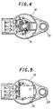
- Fig. 4 is a plan view showing an internal structure of a holder of a low-voltage terminal socket portion of the engine igniting coil device shown in Fig. 1.
- Fig. 5 is a plan view of an engine igniting coil device in a state that an element consisting of an igniter and a heat sink is mounted on a low-voltage terminal socket holder.
- an engine igniting coil device has a coil case 1 composed of a cylindrical case 2 and a case 3 having a small tubular hole 4 in its center portion and fitted in an open end of the case 2 to form a closed end of the coil case 1.
- the coil case 1 accommodates an assembly of a coil bobbin 6 with a primary coil 5 having a hollow shaft with a rode-shape core 9 inserted therein and a coil bobbin 8 with a secondary coil 7 coaxially mounted on the coil bobbin 6.
- the core 9 is provided at each end with a permanent magnet 10 for obtaining a large change in magnetic flux with an interrupted primary current.
- the core 9 is composed of laminations of iron plates having different widths with a stepped nearly circular section so that a magnetic flux may be effectively produced by increasing its space factor in the hollow shaft of the cylindrical coil bobbin 6.
- a high-voltage terminal holder 11 is a center projection formed integrally with the flanged end portion of the secondary coil bobbin 8.
- a high-voltage terminal 12 bonded to the holder 11 has a contact 13 attached thereto for providing electrical connection with an ignition plug 15.
- the assembly of the primary coil bobbin 6, secondary coil bobbin 8, high-voltage terminal 12 and contact 13 is mounted at a given place and fixed in the coil case in such a manner that a holder portion of the high-voltage terminal 12 is press-fitted in the small hole 4 of the coil case 1 and the contact 13 outwardly projected from the small hole 4.
- the coil case 1 with the assembly fixed at the given place therein is filled with melted insulating resin injected through an open-end of the coil case 1 to form a single solid device.
- the permanent magnets 10 attached one to each end of the core 9 are covered with damping members 14, respectively, which can prevent intrusion of melted resin into the core 9 and absorb relatively large thermal stress produced in the longitudinal direction of the core 9, thus preventing cracking of the resin layer formed round the core 9.
- a space formed between the primary coil bobbin 6 and the secondary coil bobbin 8 is filled with melted resin entered therein through a plurality of holes 18 made in the high-voltage terminal holder 11 of the flanged end portion of the secondary coil bobbin 8.
- Two bobbins are fixed to each other with the resin layer formed therebetween.
- the case 3 also functions as a connector of the ignition plug 15 and is provided at its top end with a plug rubber 16 for holding the ignition plug 15.
- a tip of the ignition plug 15 comes into contact with the contact 13, making electrical connection of the ignition coil device.
- the case 2 made of dielectomagnetic material having a high permeability, e.g., silicone steel, which has an electromagnetic shielding effect and acts as a side core for concentrating a lager portion of magnetic flux produced by the open-magnetic-circuit type core 9 to the case 2, thus preventing loss of the produced magnetic flux by passing a cylinder block of the engine not to cause a drop of a secondary output voltage.
- the case 2 itself has a thermal radiation effect.
- An optimal length of the case 2 lies within the range of 1 to 1.3-times the length of the core 9.
- the magnetic flux produced by the core 9 may expand with an increased magnetic resistance if the case 2 is shorter than the above-mentioned value. The longer case 2 has no effect.
- the case 3 has a plurality of ribs 30 formed between the small hole 4 and the side wall to assure an insulation distance between the high-voltage terminal 12 fitted in the small hole 4 and the case 2.
- the case 2 has a slit 33 to form a gap of 0.5 to 1.5 mm in longitudinal direction and a C-shaped section to minimize an eddy current core loss.
- the case 2 is internally covered with an elastic member 17 (e.g., rubber, elastomer) which separates resin layer from the inner wall of the case 2 and absorbs thermal stress of metal, thus preventing the resin layer from cracking.
- This interposed member 17 is can effectively prevent deterioration of the resin layer due to leakage current and can therefore improve safety and durability of the device.
- a low-voltage terminal socket holder 18 is fitted in an open top-end of the case 2.
- An igniter 19 and an element 35 including a heat sink 34 are mounted with the heat sink 34 up in the holder 18.
- Melted resin is poured from the top into the holder 18 until the element 35 is immersed in liquid resin (level L in Fig. 1), then a cap 20 with ribs 21 is laid on the holder 18 in such a way that the ribs 21 are inserted in the liquid resin layer above the heat sink 34.
- the cap 20 and the holder 18 are thus integrally formed with the top-end of the case 2.
- the element 35 with the heat sink 34 is integrally formed with the igniter 19 by laying the heat sink 34 on the igniter and covering with an even-thick (1-5 mm) layer of resin that has thermoplasticity for relaxing thermal stress and has the affinity with the potting resin.
- the resin layer of the element 35 relaxes thermal stress from the core 9 not to damage the igniter 19.
- the resin layer of the element 19 can not be stripped off and is effective to protect the surrounding resin layer against thermal stress cracking.
- the heat sink 34 in the element 35 can effectively release heat of the igniter 19 because it is arranged on opposite side to the heat-generating core 9.
- the cap 20 has a plurality of the ribs 21 that serve as a cushion for dispersing thermal stress to the resin layer, thus preventing cracking of the resin layer on the igniter 19.
- Heat from the heat-sink 34 is effectively disposed through the ribs 21 potted in the resin layer above the heat sink 34.
- the cap 20 has an air vent hole 22 through which internal pressure can be released without moving up the cap 20 mounted on the device and inside heat is also effectively brought out.
- Fig. 4 shows an internal structure of the low-voltage-terminal socket holder 18 with the removed cap 20.
- Fig. 5 shows the low-voltage-terminal socket holder 18 with element 35 mounted therein.
- the holder 18 contains connecting terminals T1 - T3 of the igniter 19, which can engage with terminals of the igniter 19 when the element 35 is only mounted at a given place in the holder 18.
- the low-voltage-terminal socket 18 is fitted on an outwardly bent portion 29 of the elastic member 17 provided on the inside wall of the case 2 to assure a high sealing quality.
- the case 2 under the low-voltage-terminal socket holder 18 is provided with a rubber seal 24 that is used when the coil case 1 is mounted in cylinder bore 23 made in a cylinder head portion of an engine.
- this ignition coil device With the coil case 1 embedded in the cylinder bore 23, this ignition coil device is secured at its flange 25 to the cylinder head with a bolt 26 through the flange 25 integrally formed with the holder 18.
- a plug rubber 16 has a flange 36 formed at its circumference. This flange 36 has the same diameter as the diameter of the cylinder bore 23 and serves as a guide for inserting the coil case 1 into the cylinder bore 23 to assure the reliable connection with the ignition plug 15.
- the engine vibration transmitted through the ignition plug 15 to the coil case 1 is absorbed by the flange 23.
- the vibration applied to electrical connections between the contact 13 and the ignition plug 15 can be suppressed, thus the durability of the device is improved.
- the present invention provides an engine ignition coil device that has the following improvements:
- an engine igniting coil device which comprises a coil case composed of a first cylindrical case and a second cylindrical case having a small tubular hole in its center portion and fitted at its open end in an open end of the first case to form a close end of the coil case and an internal assembly composed of a primary side coil bobbin, a secondary-side coil bobbin having a high-voltage terminal holder projecting from a center of its end flange portion, a rod-shape core and a high-voltage terminal attached to the high-voltage terminal holder and having a contact for electrically connecting an ignition plug thereto, the assembly is mounted in the coil case by inserting the high-voltage terminal holder in the small tubular hole of the secondary case in such a way a tip of the contact is projecting outwards from the hole, then melted insulating resin is injected through an open-end of the coil case to form a single solid device with solidified resin therein.
- the inner assembly can be easily located and reliably fixed at a given place in the coil case with no additional member, assuring precise forming of an integral device by potting with resin and reliable electrical connections with an igniting plug directly attached to the device.
- the device is easy to manufacture with an increased quality.
- the first case for accommodating therein the inner assembly is a cylinder made of metal having a high magnetic permeability, which has a gap-forming slit in the longitudinal direction thereof.
- the first case is covered internally with an elastic member and an insulating resin layer is formed between the covering member and the assembly.
- This elastic covering can effectively absorb thermal stress, thereby preventing thermal-stress cracking of the solidified resin-layer.
- the resin layer can therefore serve as a high quality insulation with no leakage current from the core, assuring reliable and safe operation of the device.
- the low-voltage terminal-socket holder is inserted into an open end of a coil case for communication with the internal assembly mounted therein and an igniter is mounted in the socket holder, thus the igniter is easily mounted without additional wiring and the assembly work is improved.
- the socket holder wherein the igniter is mounted with a heat sink up is filled with melted resin until the igniter and the heat sink are completely immersed in the liquid resin and, then, covered with a cap with its ribs immersed in the liquid resin to form a solid unit, thus assuring reliable structure of the igniter with an excellent cooling efficiency.
- a coil case is of the three-piece type that is composed of: a first cylindrical case for accommodating therein an ignition coil assembly; a second case fitted in the open bottom-end of the first case and attached to a plug for electrically connecting thereto a secondary high-voltage terminal; and a low-voltage terminal socket fitted in the open top-end of the first case.
- the ignition coil device can be available with size-and-shape variations of low-voltage terminals adaptable to variations of mounting seats in engine cylinder head portions.
- An engine igniting coil device which comprises a coil case composed of a first cylindrical case and a second case having a small tubular hole in its center portion and fitted at its open end in an open end of the first case to form a close end of the coil case and an internal unit assembled from a primary side coil bobbin, a secondary-side coil bobbin having a high-voltage terminal holder projecting from a center of its end flange portion, a rod-shape core and a high-voltage terminal attached to the high-voltage terminal holder and having a contact for electrically connecting an ignition plug thereto and which is characterized in that the internal assembly is mounted in the coil case by inserting the high-voltage terminal holder in the small tubular hole of the secondary case with a tip of the contact projected outwardly therefrom and formed integrally with the coil case by injecting melted insulating resin into the coil case: thus, the inner assembly can be easily located and reliably fixed at a given place in the coil case with no additional member, assuring precise forming
Landscapes
- Engineering & Computer Science (AREA)
- Chemical & Material Sciences (AREA)
- Combustion & Propulsion (AREA)
- Power Engineering (AREA)
- Mechanical Engineering (AREA)
- General Engineering & Computer Science (AREA)
- Ignition Installations For Internal Combustion Engines (AREA)
Applications Claiming Priority (9)
| Application Number | Priority Date | Filing Date | Title |
|---|---|---|---|
| JP35484195 | 1995-12-27 | ||
| JP354840/95 | 1995-12-27 | ||
| JP354841/95 | 1995-12-27 | ||
| JP35484095 | 1995-12-27 | ||
| JP35484095A JP3250135B2 (ja) | 1995-12-27 | 1995-12-27 | エンジンの点火コイル装置 |
| JP35484195A JP3250136B2 (ja) | 1995-12-27 | 1995-12-27 | エンジンの点火コイル装置 |
| JP35487895A JP3250137B2 (ja) | 1995-12-28 | 1995-12-28 | エンジンの点火コイル装置 |
| JP35487895 | 1995-12-28 | ||
| JP354878/95 | 1995-12-28 |
Publications (2)
| Publication Number | Publication Date |
|---|---|
| EP0782231A1 true EP0782231A1 (de) | 1997-07-02 |
| EP0782231B1 EP0782231B1 (de) | 1999-09-22 |
Family
ID=27341494
Family Applications (1)
| Application Number | Title | Priority Date | Filing Date |
|---|---|---|---|
| EP96120612A Expired - Lifetime EP0782231B1 (de) | 1995-12-27 | 1996-12-20 | Zündspulenvorrichtung für Verbrennungsmotor |
Country Status (5)
| Country | Link |
|---|---|
| US (1) | US5870012A (de) |
| EP (1) | EP0782231B1 (de) |
| KR (2) | KR100232748B1 (de) |
| DE (1) | DE69604375T2 (de) |
| TW (1) | TW359721B (de) |
Cited By (6)
| Publication number | Priority date | Publication date | Assignee | Title |
|---|---|---|---|---|
| EP0827165A3 (de) * | 1996-08-31 | 1998-10-28 | Toyo Denso Kabushiki Kaisha | Zündspulenvorrichtung für Brennkraftmaschine |
| EP0827163A3 (de) * | 1996-08-31 | 1998-11-18 | Toyo Denso Kabushiki Kaisha | Zündspulenvorrichtung für Brennkraftmaschine |
| DE19927820C1 (de) * | 1998-10-27 | 2000-07-06 | Bremi Auto Elektrik Ernst Brem | Stabzündspule |
| US6208231B1 (en) | 1997-02-14 | 2001-03-27 | Denso Corporation | Stick-type ignition coil having improved structure against crack or dielectric discharge |
| WO2004051677A3 (de) * | 2002-12-05 | 2004-08-19 | Bosch Gmbh Robert | Stabzündspule |
| US6930583B2 (en) | 1997-02-14 | 2005-08-16 | Denso Corporation | Stick-type ignition coil having improved structure against crack or dielectric discharge |
Families Citing this family (37)
| Publication number | Priority date | Publication date | Assignee | Title |
|---|---|---|---|---|
| FR2751379B1 (fr) * | 1996-07-17 | 1998-10-09 | Sagem | Bobine d'allumage |
| JPH10199737A (ja) * | 1996-11-18 | 1998-07-31 | Matsushita Electric Ind Co Ltd | 内燃機関の点火コイル装置 |
| JP3449183B2 (ja) * | 1997-05-22 | 2003-09-22 | 株式会社デンソー | 点火コイル |
| JPH11111543A (ja) * | 1997-10-07 | 1999-04-23 | Mitsubishi Electric Corp | 内燃機関用点火コイル装置 |
| DE29821239U1 (de) * | 1998-11-27 | 2000-03-30 | Robert Bosch Gmbh, 70469 Stuttgart | Zündungsanlage für eine Brennkraftmaschine |
| JP3550643B2 (ja) * | 1998-12-14 | 2004-08-04 | 株式会社デンソー | 内燃機関用点火コイル |
| US6114933A (en) * | 1999-09-08 | 2000-09-05 | Visteon Global Technologies, Inc. | Pencil ignition coil assembly module environmental shield |
| US6094122A (en) * | 1999-09-08 | 2000-07-25 | Ford Motor Company | Mechanical locking connection for electric terminals |
| US6178957B1 (en) | 1999-09-08 | 2001-01-30 | Visteon Global Technologies, Inc. | Pencil ignition coil assembly module |
| US6087918A (en) * | 1999-10-20 | 2000-07-11 | Delphi Technologies, Inc. | Twist lock ignition coil |
| USD451469S1 (en) | 1999-11-05 | 2001-12-04 | Weastec, Inc. | Ignition coil |
| US20020057170A1 (en) * | 1999-11-08 | 2002-05-16 | Albert Anthony Skinner | Ignition coil |
| US6215385B1 (en) | 1999-11-12 | 2001-04-10 | Delphi Technologies, Inc. | Ignition coil with primary winding outside of secondary winding |
| JP4318273B2 (ja) * | 1999-12-24 | 2009-08-19 | 株式会社デンソー | 点火コイル |
| KR20020043803A (ko) * | 2000-12-04 | 2002-06-12 | 배길훈 | 자동차용 스틱코일 어셈블리 |
| US20020101315A1 (en) * | 2001-01-31 | 2002-08-01 | Colin Hamer | Ignition coil with primary winding release |
| US6809621B2 (en) * | 2001-05-31 | 2004-10-26 | Denso Corporation | Internal combustion engine ignition coil, and method of producing the same |
| US6463919B1 (en) | 2001-09-24 | 2002-10-15 | Delphi Technologies, Inc. | Ignition coil with polyimide case and/or secondary spool |
| US20040027222A1 (en) * | 2002-08-06 | 2004-02-12 | Hazelwood John E. | Ignition apparatus having high density cylindrical laminated core |
| FR2855317B1 (fr) * | 2003-05-22 | 2008-09-26 | Electricfil | Procede de fabrication d'une bobine d'allumage individuel et bobine ainsi obtenue |
| JP4349198B2 (ja) * | 2004-04-30 | 2009-10-21 | 株式会社デンソー | スティック形点火コイル |
| JP4701835B2 (ja) * | 2004-07-27 | 2011-06-15 | 株式会社デンソー | スティック形点火コイル |
| DE102005039761B4 (de) * | 2005-08-23 | 2014-04-03 | Robert Bosch Gmbh | Kernbaugruppe, insbesondere für eine Zündspule einer Brennkraftmaschine |
| JP4311412B2 (ja) * | 2006-04-11 | 2009-08-12 | 三菱電機株式会社 | 点火コイル装置 |
| JP5018319B2 (ja) * | 2007-08-01 | 2012-09-05 | 株式会社デンソー | 点火コイル |
| JP4892599B2 (ja) * | 2009-10-09 | 2012-03-07 | 東洋電装株式会社 | エンジンのプラグホール防水装置 |
| US20120105189A1 (en) * | 2010-11-01 | 2012-05-03 | Tsai Hong-Jen | Ignition coil for spark plugs |
| DE102010062349A1 (de) * | 2010-12-02 | 2012-06-06 | Robert Bosch Gmbh | Zündspule mit integrierter Elektronik |
| US8839752B2 (en) | 2011-01-14 | 2014-09-23 | John A. Burrows | Corona igniter with magnetic screening |
| JP5618870B2 (ja) * | 2011-03-08 | 2014-11-05 | 株式会社デンソー | 内燃機関用点火コイル |
| JP5434966B2 (ja) * | 2011-06-06 | 2014-03-05 | 株式会社デンソー | 点火コイル |
| US9097232B2 (en) * | 2011-10-26 | 2015-08-04 | Delphi Technologies, Inc. | Ignition coil assembly |
| US9461444B2 (en) | 2014-07-15 | 2016-10-04 | Cummins Inc. | Fan cooled ignition coil method and apparatus |
| DE102015201167B3 (de) * | 2015-01-23 | 2016-06-23 | Ford Global Technologies, Llc | Zündkerze zum Einleiten einer Verbrennung in einem Zylinder eines Verbrennungsmotors sowie Verfahren zum Betreiben einer derartigen Zündkerze |
| US9947451B1 (en) | 2016-10-11 | 2018-04-17 | Diamond Electric Mfg. Corp. | Ignition coil |
| WO2019236963A1 (en) * | 2018-06-07 | 2019-12-12 | Nypro Inc. | Apparatus, system, and method of providing a sheet product replenishment monitor |
| US11319917B2 (en) * | 2019-06-14 | 2022-05-03 | Denso International America, Inc. | Ignition coil and ignition system for a vehicle |
Citations (3)
| Publication number | Priority date | Publication date | Assignee | Title |
|---|---|---|---|---|
| FR2624559A3 (fr) * | 1987-12-14 | 1989-06-16 | Magneti Marelli Spa | Bobine d'allumage, en particulier pour moteurs de course |
| JPH0423296U (de) | 1990-06-14 | 1992-02-26 | ||
| JPH0587034A (ja) | 1991-09-24 | 1993-04-06 | Nippondenso Co Ltd | 内燃機関用点火装置 |
Family Cites Families (1)
| Publication number | Priority date | Publication date | Assignee | Title |
|---|---|---|---|---|
| JPH0423296A (ja) * | 1990-05-18 | 1992-01-27 | Fuji Photo Film Co Ltd | 集積回路およびその使用方法 |
-
1996
- 1996-12-19 US US08/770,091 patent/US5870012A/en not_active Expired - Fee Related
- 1996-12-20 TW TW085115951A patent/TW359721B/zh not_active IP Right Cessation
- 1996-12-20 DE DE69604375T patent/DE69604375T2/de not_active Expired - Lifetime
- 1996-12-20 EP EP96120612A patent/EP0782231B1/de not_active Expired - Lifetime
- 1996-12-26 KR KR1019960072086A patent/KR100232748B1/ko not_active Expired - Fee Related
- 1996-12-26 KR KR1019960072086A patent/KR970045378A/ko active Granted
Patent Citations (3)
| Publication number | Priority date | Publication date | Assignee | Title |
|---|---|---|---|---|
| FR2624559A3 (fr) * | 1987-12-14 | 1989-06-16 | Magneti Marelli Spa | Bobine d'allumage, en particulier pour moteurs de course |
| JPH0423296U (de) | 1990-06-14 | 1992-02-26 | ||
| JPH0587034A (ja) | 1991-09-24 | 1993-04-06 | Nippondenso Co Ltd | 内燃機関用点火装置 |
Non-Patent Citations (1)
| Title |
|---|
| PATENT ABSTRACTS OF JAPAN vol. 017, no. 423 (M - 1458) 6 August 1993 (1993-08-06) * |
Cited By (12)
| Publication number | Priority date | Publication date | Assignee | Title |
|---|---|---|---|---|
| EP0827165A3 (de) * | 1996-08-31 | 1998-10-28 | Toyo Denso Kabushiki Kaisha | Zündspulenvorrichtung für Brennkraftmaschine |
| EP0827163A3 (de) * | 1996-08-31 | 1998-11-18 | Toyo Denso Kabushiki Kaisha | Zündspulenvorrichtung für Brennkraftmaschine |
| EP0964413A3 (de) * | 1996-08-31 | 2000-12-06 | Toyo Denso Kabushiki Kaisha | Zündspulenvorrichtung für Verbrennungsmotor |
| US6208231B1 (en) | 1997-02-14 | 2001-03-27 | Denso Corporation | Stick-type ignition coil having improved structure against crack or dielectric discharge |
| US6525636B1 (en) | 1997-02-14 | 2003-02-25 | Denso Corporation | Stick-type ignition coil having improved structure against crack or dielectric discharge |
| US6930583B2 (en) | 1997-02-14 | 2005-08-16 | Denso Corporation | Stick-type ignition coil having improved structure against crack or dielectric discharge |
| US6977574B1 (en) | 1997-02-14 | 2005-12-20 | Denso Corporation | Stick-type ignition coil having improved structure against crack or dielectric discharge |
| US6995644B2 (en) | 1997-02-14 | 2006-02-07 | Denso Corporation | Stick-type ignition coil having improved structure against crack or dielectric discharge |
| US7068135B1 (en) | 1997-02-14 | 2006-06-27 | Denso Corporation | Stick-type ignition coil having improved structure against crack or dielectric discharge |
| US7071804B2 (en) | 1997-02-14 | 2006-07-04 | Denso Corporation | Stick-type ignition coil having improved structure against crack or dielectric discharge |
| DE19927820C1 (de) * | 1998-10-27 | 2000-07-06 | Bremi Auto Elektrik Ernst Brem | Stabzündspule |
| WO2004051677A3 (de) * | 2002-12-05 | 2004-08-19 | Bosch Gmbh Robert | Stabzündspule |
Also Published As
| Publication number | Publication date |
|---|---|
| EP0782231B1 (de) | 1999-09-22 |
| US5870012A (en) | 1999-02-09 |
| KR970045378A (ko) | 1997-07-26 |
| TW359721B (en) | 1999-06-01 |
| KR100232748B1 (ko) | 1999-12-01 |
| DE69604375D1 (de) | 1999-10-28 |
| DE69604375T2 (de) | 2000-01-05 |
Similar Documents
| Publication | Publication Date | Title |
|---|---|---|
| EP0782231B1 (de) | Zündspulenvorrichtung für Verbrennungsmotor | |
| EP0951028B1 (de) | Zündspulenvorrichtung für Verbrennungsmotor | |
| EP1253606B1 (de) | Stiftförmige Zündspule mit verbesserter Struktur zur Vermeidung von Rissen oder dielektrischer Entladung | |
| EP0827163B1 (de) | Zündspulenvorrichtung für Brennkraftmaschine | |
| HU231395B1 (hu) | Gyújtótekercs belsőégésű motorhoz, valamint annak gyártási eljárása | |
| EP0827164A2 (de) | Zündspulenvorrichtung für Brennkraftmaschine und Verfahren zum Wickeln einer Zündspule | |
| EP0785605A1 (de) | Zündspulenvorrichtung für Verbrennungsmotor | |
| JP3550643B2 (ja) | 内燃機関用点火コイル | |
| JPH0917662A (ja) | 内燃機関用点火装置 | |
| JP3250135B2 (ja) | エンジンの点火コイル装置 | |
| JP3752745B2 (ja) | エンジンの点火コイル装置 | |
| JP3250136B2 (ja) | エンジンの点火コイル装置 | |
| JP3250137B2 (ja) | エンジンの点火コイル装置 | |
| JP3713641B2 (ja) | エンジンの点火コイル装置 | |
| JP3752743B2 (ja) | エンジンの点火コイル装置 | |
| JPH1074646A (ja) | エンジンの点火コイル装置 | |
| JP3752742B2 (ja) | エンジンの点火コイル装置 | |
| JP3706979B2 (ja) | エンジンの点火コイル装置 | |
| JP2000208346A (ja) | 内燃機関用点火コイル及びその製造方法 | |
| JPH10106864A (ja) | エンジンの点火コイル装置 | |
| JPS63164307A (ja) | 内燃機関用点火コイル | |
| JPH1074647A (ja) | エンジンの点火コイル装置 |
Legal Events
| Date | Code | Title | Description |
|---|---|---|---|
| PUAI | Public reference made under article 153(3) epc to a published international application that has entered the european phase |
Free format text: ORIGINAL CODE: 0009012 |
|
| AK | Designated contracting states |
Kind code of ref document: A1 Designated state(s): DE GB |
|
| 17P | Request for examination filed |
Effective date: 19970704 |
|
| 17Q | First examination report despatched |
Effective date: 19970903 |
|
| GRAG | Despatch of communication of intention to grant |
Free format text: ORIGINAL CODE: EPIDOS AGRA |
|
| GRAG | Despatch of communication of intention to grant |
Free format text: ORIGINAL CODE: EPIDOS AGRA |
|
| GRAH | Despatch of communication of intention to grant a patent |
Free format text: ORIGINAL CODE: EPIDOS IGRA |
|
| GRAH | Despatch of communication of intention to grant a patent |
Free format text: ORIGINAL CODE: EPIDOS IGRA |
|
| GRAA | (expected) grant |
Free format text: ORIGINAL CODE: 0009210 |
|
| AK | Designated contracting states |
Kind code of ref document: B1 Designated state(s): DE GB |
|
| REF | Corresponds to: |
Ref document number: 69604375 Country of ref document: DE Date of ref document: 19991028 |
|
| PLBE | No opposition filed within time limit |
Free format text: ORIGINAL CODE: 0009261 |
|
| 26N | No opposition filed | ||
| REG | Reference to a national code |
Ref country code: GB Ref legal event code: IF02 |
|
| PGFP | Annual fee paid to national office [announced via postgrant information from national office to epo] |
Ref country code: GB Payment date: 20091218 Year of fee payment: 14 |
|
| PGFP | Annual fee paid to national office [announced via postgrant information from national office to epo] |
Ref country code: DE Payment date: 20090831 Year of fee payment: 14 |
|
| GBPC | Gb: european patent ceased through non-payment of renewal fee |
Effective date: 20101220 |
|
| PG25 | Lapsed in a contracting state [announced via postgrant information from national office to epo] |
Ref country code: GB Free format text: LAPSE BECAUSE OF NON-PAYMENT OF DUE FEES Effective date: 20101220 Ref country code: DE Free format text: LAPSE BECAUSE OF NON-PAYMENT OF DUE FEES Effective date: 20110701 |
|
| REG | Reference to a national code |
Ref country code: DE Ref legal event code: R119 Ref document number: 69604375 Country of ref document: DE Effective date: 20110701 |