EP0782249A1 - Système et méthode pour la suppression de signaux images - Google Patents
Système et méthode pour la suppression de signaux images Download PDFInfo
- Publication number
- EP0782249A1 EP0782249A1 EP96309248A EP96309248A EP0782249A1 EP 0782249 A1 EP0782249 A1 EP 0782249A1 EP 96309248 A EP96309248 A EP 96309248A EP 96309248 A EP96309248 A EP 96309248A EP 0782249 A1 EP0782249 A1 EP 0782249A1
- Authority
- EP
- European Patent Office
- Prior art keywords
- signal
- component
- frequency
- intermediate frequency
- local oscillator
- Prior art date
- Legal status (The legal status is an assumption and is not a legal conclusion. Google has not performed a legal analysis and makes no representation as to the accuracy of the status listed.)
- Withdrawn
Links
- 238000000034 method Methods 0.000 title claims abstract description 52
- 238000001914 filtration Methods 0.000 claims description 18
- 238000004891 communication Methods 0.000 claims description 15
- 230000000903 blocking effect Effects 0.000 claims 4
- 238000005065 mining Methods 0.000 claims 1
- 238000001228 spectrum Methods 0.000 description 31
- 230000001413 cellular effect Effects 0.000 description 24
- 238000010586 diagram Methods 0.000 description 4
- 230000003321 amplification Effects 0.000 description 3
- 238000003199 nucleic acid amplification method Methods 0.000 description 3
- 230000005540 biological transmission Effects 0.000 description 2
- 238000001514 detection method Methods 0.000 description 2
- 230000010267 cellular communication Effects 0.000 description 1
- 238000006243 chemical reaction Methods 0.000 description 1
- 230000001788 irregular Effects 0.000 description 1
- 238000010295 mobile communication Methods 0.000 description 1
- 230000001105 regulatory effect Effects 0.000 description 1
- 238000010897 surface acoustic wave method Methods 0.000 description 1
- 230000001360 synchronised effect Effects 0.000 description 1
Images




Classifications
-
- H—ELECTRICITY
- H03—ELECTRONIC CIRCUITRY
- H03D—DEMODULATION OR TRANSFERENCE OF MODULATION FROM ONE CARRIER TO ANOTHER
- H03D7/00—Transference of modulation from one carrier to another, e.g. frequency-changing
- H03D7/16—Multiple-frequency-changing
- H03D7/165—Multiple-frequency-changing at least two frequency changers being located in different paths, e.g. in two paths with carriers in quadrature
- H03D7/166—Multiple-frequency-changing at least two frequency changers being located in different paths, e.g. in two paths with carriers in quadrature using two or more quadrature frequency translation stages
-
- H—ELECTRICITY
- H03—ELECTRONIC CIRCUITRY
- H03D—DEMODULATION OR TRANSFERENCE OF MODULATION FROM ONE CARRIER TO ANOTHER
- H03D7/00—Transference of modulation from one carrier to another, e.g. frequency-changing
- H03D7/18—Modifications of frequency-changers for eliminating image frequencies
Definitions
- the invention relates to the field of methods and equipment for receiving signals transmitted over a path.
- the cellular systems concept calls for dividing a geographic area into a number of cells.
- Each cell advantageously has an associated cell site (also called a base station) which is connected via a wireless switching center to a wired phone network.
- the cell site establishes a wireless link over radio frequency (i.e., frequencies above 20,000 Hz) paths with wireless terminals (e.g., cellular phones) operated by subscribers to the system within the cell. Subscribers are then able to use their wireless terminals to send and receive information to and from other wireless terminals and to and from devices connected to the telephone network.
- radio frequency i.e., frequencies above 20,000 Hz
- wireless terminals e.g., cellular phones
- a received signal of interest must be processed by a receiver in the cellular system so as to output to a subscriber a signal (e.g., a speech signal) of sufficient quality to satisfy subscriber demands. Quality must be maintained both when the received signal of interest is of low power and when the received signal of interest operates in an environment in which other signals, of varying power levels, are received (along with the signal of interest) at the receiver's antenna.
- a signal e.g., a speech signal
- the processing of a received signal of interest in a receiver involves three major operations.
- the receiver must: 1) amplify, 2) tune and frequency translate, and 3) filter the received signal of interest.
- a receiver must first amplify a received signal of interest because the power in the received signal of interest is small, typically on the order of -100 dBm.
- the power in the received signal of interest is small, not only because the signal as originally transmitted was limited in power in accordance with the drafted standards, but also because the power of a signal will decrease as the signal propagates along or through a radio frequency (RF) link between a transmitting and receiving antenna.
- RF radio frequency
- the power in a received signal must be amplified so as to distinguish the signal of interest from other signals and noise for subsequent processing (e.g., for filtering and tuning).
- a receiver must also perform tuning and frequency translation operations.
- the atmosphere advantageously supports transmission of RF signals, but not of acoustic signals or of digital baseband signals, over long distances. Consequently, cellular phone signals are transmitted by using baseband signals to vary (i.e., to modulate) some parameter (such as the frequency or phase) of an RF signal thereby translating the baseband signal into the RF range. For example, cellular phone signals may be transmitted at frequencies around 1 GHz. Consequently, upon receiving such a signal, the signal must be translated down to the baseband range before demodulation.
- a receiver must perform filtering operations.
- the antenna of a cellular phone will receive signals over communication paths from a variety of sources including other cellular phones and base stations, and thus a receiver in the cellular phone must filter out all other received signals.
- the superheterodyne receiver architecture performs amplification and filtering operations at successive stages where each stage occurs at an intermediate frequency (described below) to which the received signal of interest has been translated. The stages are continued until the received signal interest has been translated down to baseband. See, e.g., Simon Haykin, Communication Systems (3rd ed.), John Wiley & Sons, Inc., New York, 1994.
- the superheterodyne receiver architecture is illustrated in FIG. 1.
- the received signal of interest, as well as other signals and noise, are received at antenna 105.
- the spectrum of signals input to antenna 105 is spectrum 102 comprising a signal of interest centered at .95 GHz.
- the power in the signal of interest is smaller than the power in other signals received at the antenna
- Duplexer 106 advantageously acts so as to bandpass filter the signals received at antenna 105.
- the spectrum of the signal output from duplexer 106 is spectrum 107.
- the duplexer output signal is amplified in amplifier 110 and is then input to image rejection filter 112 which is designed to eliminate the "image" generation problem.
- the image generation problem is inherent with mixing or multiplication operations which are used by receivers to perform frequency translation.
- the image rejection problem is illustrated as follows. Whenever two signals (for example, a received signal of interest at frequency f1 and a local oscillator signal generated in the receiver at frequency f2 , where f2>f1) are mixed, the result will be two mixing products, one each at the sum and difference of the two signal frequencies.
- the mixing products are identical except that one is centered around a frequency of (f1+f2) and the other is centered at a frequency of (f2-f1).
- the mixing product centered at (f2-f1) is desired.
- the frequency (f2-f1) is also known as an intermediate frequency (IF).
- One class of techniques that exist for performing the image rejection task include the Hilbert transform method and Weaver's method. See, e.g., Haykin, supra, and D.K. Weaver, "A Third Method of Generation and Detection of SSB Signals," Proc. IRE, pp. 1703-1705, December 1956. Both of these methods, instead of filtering to eliminate image signals as in the superheterodyne receiver architecture, use signal cancellation techniques. In particular, the methods generate signals, equal and opposite to the image signals, and add the created signals to the image signals. The result is cancellation of both the image and created signals, thereby allowing processing of desired signals at an IF.
- a received RF signal of interest is initially converted first to "dc" (i.e. a frequency of zero) by mixing the received RF signal of interest with a local oscillator of the same frequency as a carrier frequency associated with the received RF signal.
- the resulting signal is then converted to a second, non-zero frequency.
- this method of image rejection typically does not achieve sufficient performance since the method generates a large offset signal at zero frequency (caused by the mixing of the carrier frequency and the local oscillator at the carrier frequency) that typically obscures the signal of interest.
- Weaver's method for image rejection converts a received signal of interest to a lower frequency called the first IF and then to an even lower frequency called the second IF.
- image rejection again, on the order of 60 dB or more.
- image rejection is difficult to achieve due to an inability to accurately match performance characteristics of circuit components.
- both the Hilbert transform method and Weaver's method for image rejection are difficult and expensive to implement where the signal of interest is of low power and is surrounded by signals of greater power.
- the superheterodyne architecture employs a class of techniques for image rejection based on filtering.
- the superheterodyne architecture employs image rejection filters, such as image rejection filter 112, so as to attenuate image frequencies prior to the mixing operation thereby ensuring that the only signals present at the IF frequency are those generated by mixing the received signal of interest with the local oscillator.
- the spectrum of the signal output from image rejection filter 112 is spectrum 113.
- first mixer 116 the signal is mixed with or translated by a signal generated by first oscillator 120.
- the output from first mixer 116 is applied to channel selection filter 130.
- Channel selection filter 130 is a bandpass filter centered around one of the mixing products.
- the spectrum of the signal output by channel selection filter 130 is spectrum 135.
- the filtered signal is amplified by variable gain amplifier 140 and mixed in second mixer 147 with a signal generated by second oscillator 145.
- the mixing, filtering and amplifying operations may be repeated until sufficient amplification and filtering of the signal of interest is achieved at which point the resulting signal (with spectrum 150) is input to demodulator 160, the purpose of which is to recover the signal originally generated by a system subscriber.
- the superheterodyne architecture may be used to satisfy the requirements for receiver operation even in newly drafted cellular phone standards, the architecture typically requires use of expensive filters such as surface acoustic wave filters for the filtering and tuning operations. Such expensive filters are a significant portion of the cost of circuit components in current cellular receivers.
- signals may be generated when processing a signal of interest by initially translating the signal of interest to a first, non-zero intermediate frequency (IF) and then to a second intermediate frequency higher than the first.
- IF intermediate frequency
- the present invention recognizes signals at frequencies adjacent to or near the signal of interest, although typically larger in power than the signal of interest, are also typically smaller in power than signals not adjacent to or near the signal of interest.
- the present invention recognizes that if image signals are caused by these frequencies adjacent to or near the signal of interest, a smaller amount of image rejection is required.
- the present invention recognizes that such image rejection is advantageously accomplished by converting to a lower IF first, and then to a higher IF so as to make use of components, such as filters, that can provide sufficient performance at the higher IF at relatively low cost.
- an input signal and a first mixing signal are mixed to generate a first signal at a first intermediate frequency, wherein the first intermediate frequency is a non-zero frequency; the first signal is filtered; the filtered first signal and a second mixing signal are mixed to generate a second signal at a second intermediate frequency, wherein the second intermediate frequency is higher than the first intermediate frequency; the input signal and a third mixing signal are mixed to generate a third signal at the first intermediate frequency, wherein the third mixing signal is in quadrature with the first mixing signal; the third signal is filtered; the third filtered signal and a fourth mixing signal are mixed to generate a fourth signal at the second intermediate frequency, wherein the fourth mixing signal is in quadrature with the second mixing signal; and the fourth signal and the second signal are added to generate a summed signal.
- Image signals in the fourth and second signals are advantageously equal and opposite to each other and cancel each other in the summed signal.
- FIG. 1 illustrates the architecture of a superheterodyne receiver.
- FIG. 2 illustrates a wireless communications system
- FIG. 3 is a block diagram of components comprising a wireless terminal.
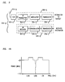
- FIG. 4A illustrates a first spectrum of signals in which a receiver is required to operate under the GSM standard.
- FIG. 4B illustrates a second spectrum of signals in which a receiver is required to operate under the GSM standard.
- FIG. 5 gives an expanded view of the spectrum of signals in which the receiver is required to operate.
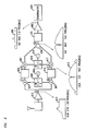
- FIG. 6 is a block diagram of the inventive apparatus for receiving a signal.
- FIG. 7 illustrates steps in the inventive method for receiving a signal.
- FIGs. 8A-8D are plots of example spectra of signals generated by the inventive apparatus.
- FIG. 2 illustrates a system in which the inventive method and apparatus may be used.
- FIG. 2 illustrates a type of wireless communications system called a cellular system.
- the geographic area serviced by the system is usually partitioned into a number of tessellated areas or cells 201-i.
- each cell is represented as a hexagon; in practice, however, each cell typically has an irregular shape that depends on the topology of the geographic area serviced by the system.
- Each cell is a respective cell site or base station 202-I.
- Base station 202-i is advantageously connected, via wireless switching center 205, to wired telephone network 207.
- Base station 202-i and wireless switching center 205 comprise the wireless infrastructure.
- Each cell site 202-i establishes wireless communications via radio frequency (RF) comunication paths with wireless terminals 203-i,j operated by system subscribers within the cell for transmitting and receiving information (e.g. signals representing data, speech, video, text) from wireless terminals (including those in other cells) and from devices 209-k (e.g., telephones and fax machines) connected to telephone network 207.
- RF radio frequency
- FIG. 3 is a block diagram of components comprising wireless terminal 203-i,j which illustratively herein is a cellular phone for sending and receiving speech signals.
- Wireless terminal 203-i,j advantageously receives a signal of interest from base station 202-i.
- Wireless terminal 203-i,j advantageously comprises transmitter 350-i,j and receiver 370-i,j.
- Transmitter 350-i,j in turn comprises transducer 356-i,j, modulator 354-i,j and RF transmitter 352-i,j.
- Receiver 370-i,j and transmitter 350-i,j share, via device 302 ( e.g., a switch or a duplexer), antenna 315-i,j.
- device 302 e.g., a switch or a duplexer
- transducer 309-i,j takes a baseband signal, such as speech, and converts it into electrical signals.
- the electrical signals are input to modulator 354-i,j which uses the electrical signals to vary ( i.e., to modulate) some parameter of an RF signal.
- modulator 354-i,j uses the electrical signals to vary ( i.e., to modulate) some parameter of an RF signal.
- the GSM standard uses a type of RF modulation called Gaussian Minimum shift key modulation.
- the modulated RF signal is transmitted along a communications path by RF transmitter 352-i,j over an RF link via antenna 315-i,j.
- Receiver 370-i,j comprises RF receiver 372-i,j, demodulator 374-i,j and transducer 376-i,j.
- RF receiver 372-i,j takes the signal of interest at antenna 315-i,j and filters, amplifies and translates the signal so that demodulator 374-i,j may recover an electrical signal representing the variation of a parameter used to modulate the received signal of interest.
- the demodulator may be either an analog or digital demodulator.
- the demodulator may use, for example, synchronous or envelope detection techniques depending on the modulation scheme used to transmit the information.
- the electrical signal is then converted by transducer 376-i,j to an acoustic signal.
- the wireless infrastructure e.g., the base stations and the wireless switching centers
- wireless terminals may be manufactured by different entities, they are compatible with each other because they comply with one or more standards which regulate the electromagnetic interface between them (e.g., the Advanced Mobile Phone Service and GSM standards).
- the Advanced Mobile Phone Service and GSM standards e.g., the Advanced Mobile Phone Service and GSM standards.
- One aspect that is regulated by standards is the performance of receivers of wireless terminals.
- the ability of a receiver e.g., RF receiver 372-i,j) to properly receive a signal of interest (i.e., to take a received signal of interest and to output a baseband signal of satisfactory quality) is specified.
- a receiver e.g., RF receiver 372-i,j
- a signal of interest i.e., to take a received signal of interest and to output a baseband signal of satisfactory quality
- FIG. 4A illustrates an example of one requirement for receiver operation for the illustrative example as specified by the GSM standard (the signals below .90 GHz and above 1.0 GHz have been reduced to reflect filtering such as that performed by device 302 i,j).
- the receiver is required to be able to receive a signal of interest on a 200 kHz channel centered at an RF frequency of.950 GHz of power -98 dBm in the presence of signals at other frequencies and power levels as indicated in the figure.
- FIG. 4B gives an expanded view of the spectrum of FIG. 4A.
- FIG. 5 illustrates a further receiver requirement under the GSM standard in which a receiver is required to be able to receive a signal of -85 dBm in the presence of signals in adjacent channels as shown.
- the GSM standard limits the amplitude of the signals in the channels adjacent to the signal of interest to be no more than 9 dB higher than the signal of interest.
- FIG. 6 A block diagram of the inventive apparatus for use in RF receiver 372-i,j in the system of FIG. 3 is illustrated in FIG. 6.
- FIG. 7 illustrates steps in the inventive method, advantageously performed by the inventive apparatus of FIG. 6.
- the inventive method and apparatus embody the recognition that shortcomings of Weaver's method for image rejection can be overcome.
- a received RF signal is translated to a first, non-zero IF frequency and then translated up to a second, higher intermediate frequency.
- the first IF is, however, advantageously near zero as shown below.
- signals are created which advantageously are used to reject image signals caused by the translation operations.
- image rejection is accomplished, and inexpensive filters (such as those mass produced for FM radios) centered around the second IF frequency may be used for channel selection.
- the inventive method and apparatus advantageously make use of the fact that a signal of interest is received on a carrier frequency in a particular frequency range (between frequencies f L and f H ) and that other signals in that range, especially those in channels adjacent to the signal of interest, are typically of limited power, e.g. no more than 9 dB higher than the signal of interest in GSM standard, and thus image rejection of these frequencies is readily accomplished.
- the input to amplifier 612 is the spectrum of FIG. 4A.
- the spectrum of the signal output from amplifier 612 is spectrum 613.
- the signal output from amplifier 612 is input to two paths, an upper path from points A to E to F to D2 and a lower path from points A to B to C to D1.
- the two paths advantageously implement image rejection based on the recognition that the sequence of frequency conversion is not from a first IF frequency to a second, lower IF frequency but instead from a first, non-zero IF frequency to a higher IF frequency.
- the signal output from amplifier 612 is first mixed in first mixer 607 with a first mixing signal.
- the first mixing signal advantageously is a signal output from first phase splitter 606.
- the components may be regarded as sine and cosine waves where the cosine wave may be described as lagging the sine was by 90 degrees in phase.
- the signal from first local oscillator 605 is at a frequency of 949.9 MHz, i.e. at frequency in between the channel adjacent to the signal of interest and the signal of interest itself.
- the lagging component i.e. the cosine wave component
- FIG. 8A which shows only the positive frequency axis.
- Filter 614 advantageously selects the mixing product at lower frequencies in step 720.
- Filter 614 is also a dc-blocking filter, i.e.
- the filter greatly attenuates signals at dc thereby eliminating any dc components caused by self-mixing of the local oscillator (caused by the local oscillator signal feeding through to the antenna and being reflected back due to mismatches in circuit components).
- the spectrum of the signal output from filter 614 is spectrum 615 which is illustrated in greater detail in FIG. 8B. Note that the spectrum of interest, i.e. the spectrum that is shaded, is obscured by an over lapping spectrum (the spectrum marked with hatch marks) resulting from mixing products in the same frequency range (and thus not filtered out by filter 614).
- step 730 the signal output from filter 614 next mixed in second mixer 617 with a second mixing signal.
- the second mixing signal advantageously is a signal output from second phase splitter 618.
- Second phase splitter 618 splits a signal input from second local oscillator 619 into a first component and a second component where the phase of the components are in quadrature.
- the components may be regarded as negative sine and cosine waves where the negative sine wave may be described as lagging the cosine was by 90 degrees in phase.
- the signal from second local oscillator 619 is illustratively at a frequency of either 10.6 or 10.8 Mhz. Assume the cosinge wave component is input to second mixer 617.
- the two signals input to second mixer 617 are illustrated FIG. 8C.
- the output of second mixer 617 is input to system 630 at point D1.
- step 740 the signal output from amplifier 612 along path A to E to F to D is first mixed in third mixer 647 with a third mixing signal.
- Third mixing signal advantageously is a component output from first phase splitter 606.
- first phase splitter 606 splits a signal input from first local oscillator 605 into two components where the phases of the components are in quadrature .
- the component not input to first mixer 607 from first phase splitter 606 is input to third mixer 647, i.e. consistent with the choice of signal component input to mixer 607 above, in this example the leading or sine component is input to third mixer 647.
- the resulting spectrum of the signal output from third mixer 647 is the same as the spectrum output from first mixer 607 but with amplitudes of negative frequency components inverted.
- Filter 664 advantageously selects the mixing product at lower frequencies in step 750.
- Filter 664 is also advantageously a dc-blocking filter.
- step 760 the signal output from low pass filter 664 next mixed in fourth mixer 667 with a fourth mixing signal.
- the fourth mixing signal advantageously is a signal output from second phase splitter 618.
- the signal output from second phase splitter 618 is the lagging or negative sine component of second local oscillator 619.
- the signal from second local oscillator 619 is at a frequency of either 10.6 or 10.8 MHz.
- the output of mixer 667 is input to system 630 at point D2 in step 770.
- System 630 (which, for example, may comprise a summer) then advantageously generates an output signal as a function of the signal output from mixer 607 and the signal output from mixer 667.
- the input to system 630 advantageously is two signals whose spectra are such that the components representing the signal of interest are in phase but where the components representing image signals are 180° out of phase so that when the signals are summed together the result is simply the signal of interest.
- the resulting signal is centered at 10.7 MHz, a frequency at which high performance, passive and inexpensive filters are available for use as filter 675. Such filters are available, in part, due to the demand for filters in this frequency range for use in receiving FM broadcast signals in devices such as car radios and home stereos.
- the spectrum of the output signal, after bandpass filtering through filter 675 and amplification in amplifier 680, is spectrum 685.
- the output of filter 680 is then input to demodulator 690 to recover the baseband signal used to modulate to the received signal.
- inventive method and apparatus have been described without reference to specific hardware or software. Instead the method and apparatus have been described in such a way that those skilled in the art can readily adapt such hardware or software as may be available or preferable. While the above teaching of the inventive method and apparatus has been in the context of transmitting speech signals via a cellular phone system, those skilled in the art will recognize the applicability of these teaching to other contexts. For example, other information signals, such a video signals, may be transmitted. Also, the inventive method and apparatus are not limited to processing received signals of interest according to the GSM standard. Signals compatible with other cellular and wireless standards, such as the IS-96 and IS-136 standards, may also be processed using the inventive method and apparatus using appropriate detectors to recover baseband signals.
- the inventive method and apparatus may be used for wireless communications applications, other than cellular phone applications, such as FSK (frequency shift key) and DQPSK (differential quadriphase shift keying) transmission. Moreover, the inventive method and apparatus may be used for paths for wired RF communication applications such as cable television systems.
- FSK frequency shift key
- DQPSK differential quadriphase shift keying
Landscapes
- Engineering & Computer Science (AREA)
- Power Engineering (AREA)
- Superheterodyne Receivers (AREA)
Applications Claiming Priority (2)
| Application Number | Priority Date | Filing Date | Title |
|---|---|---|---|
| US59119095A | 1995-12-26 | 1995-12-26 | |
| US591190 | 1995-12-26 |
Publications (1)
| Publication Number | Publication Date |
|---|---|
| EP0782249A1 true EP0782249A1 (fr) | 1997-07-02 |
Family
ID=24365446
Family Applications (1)
| Application Number | Title | Priority Date | Filing Date |
|---|---|---|---|
| EP96309248A Withdrawn EP0782249A1 (fr) | 1995-12-26 | 1996-12-18 | Système et méthode pour la suppression de signaux images |
Country Status (3)
| Country | Link |
|---|---|
| EP (1) | EP0782249A1 (fr) |
| JP (1) | JPH09214385A (fr) |
| CA (1) | CA2190545A1 (fr) |
Cited By (9)
| Publication number | Priority date | Publication date | Assignee | Title |
|---|---|---|---|---|
| EP0948129A1 (fr) * | 1998-03-30 | 1999-10-06 | TELEFONAKTIEBOLAGET L M ERICSSON (publ) | Mélangeur à réjection de fréquence image pour un récepteur de radio |
| WO1999062199A1 (fr) * | 1998-05-27 | 1999-12-02 | Nokia Corporation | Recepteur et procede de reception de communications sans fil |
| GB2341502A (en) * | 1998-09-08 | 2000-03-15 | Mitel Semiconductor Ltd | Image reject mixer |
| GB2345230A (en) * | 1998-12-23 | 2000-06-28 | Nokia Mobile Phones Ltd | Image rejection filters for quadrature radio receivers |
| US6144845A (en) * | 1997-12-31 | 2000-11-07 | Motorola, Inc. | Method and circuit for image rejection |
| US6973297B1 (en) | 1999-09-01 | 2005-12-06 | Sirific Wireless Corporation | Method and apparatus for down-conversion of radio frequency (RF) signals with reduced local oscillator leakage |
| WO2006085046A1 (fr) * | 2004-09-20 | 2006-08-17 | Frontier Silicon Limited | Circuits de recepteurs radio a basse frequence intermediaire (if) |
| GB2427091A (en) * | 2005-06-08 | 2006-12-13 | Zarlink Semiconductor Ltd | Baseband quadrature frequency down-converter receiver having quadrature up-converter stage |
| EP1944864A3 (fr) * | 2007-01-09 | 2012-08-29 | Rohde & Schwarz GmbH & Co. KG | Convertisseur de fréquence |
Families Citing this family (4)
| Publication number | Priority date | Publication date | Assignee | Title |
|---|---|---|---|---|
| EP1208499A4 (fr) * | 1999-05-19 | 2007-11-07 | Digimarc Corp | Procedes et systemes utilisant le filigrane numerique dans des supports musicaux et autres |
| JP4179782B2 (ja) | 2000-04-26 | 2008-11-12 | 富士通株式会社 | 無線受信装置及び無線通信システム |
| JP2002076975A (ja) * | 2000-08-17 | 2002-03-15 | Samsung Electronics Co Ltd | デジタルダウンコンバータ、及び受信機 |
| DE102004054893A1 (de) * | 2004-11-12 | 2006-05-24 | Micronas Gmbh | Verfahren und Schaltungsanordnung zur Kanalfilterung analog oder digital modulierter TV-Signale |
Citations (3)
| Publication number | Priority date | Publication date | Assignee | Title |
|---|---|---|---|---|
| DE3412190A1 (de) * | 1984-04-02 | 1985-10-10 | Telefunken electronic GmbH, 7100 Heilbronn | Integrierbare empfaengerschaltung |
| US4944025A (en) * | 1988-08-09 | 1990-07-24 | At&E Corporation | Direct conversion FM receiver with offset |
| GB2242588A (en) * | 1990-03-28 | 1991-10-02 | Silcom Research Limited | Double conversion receiver with image suppression |
-
1996
- 1996-11-18 CA CA 2190545 patent/CA2190545A1/fr not_active Abandoned
- 1996-12-18 EP EP96309248A patent/EP0782249A1/fr not_active Withdrawn
- 1996-12-24 JP JP34374896A patent/JPH09214385A/ja active Pending
Patent Citations (3)
| Publication number | Priority date | Publication date | Assignee | Title |
|---|---|---|---|---|
| DE3412190A1 (de) * | 1984-04-02 | 1985-10-10 | Telefunken electronic GmbH, 7100 Heilbronn | Integrierbare empfaengerschaltung |
| US4944025A (en) * | 1988-08-09 | 1990-07-24 | At&E Corporation | Direct conversion FM receiver with offset |
| GB2242588A (en) * | 1990-03-28 | 1991-10-02 | Silcom Research Limited | Double conversion receiver with image suppression |
Cited By (14)
| Publication number | Priority date | Publication date | Assignee | Title |
|---|---|---|---|---|
| US6144845A (en) * | 1997-12-31 | 2000-11-07 | Motorola, Inc. | Method and circuit for image rejection |
| EP0948129A1 (fr) * | 1998-03-30 | 1999-10-06 | TELEFONAKTIEBOLAGET L M ERICSSON (publ) | Mélangeur à réjection de fréquence image pour un récepteur de radio |
| WO1999062199A1 (fr) * | 1998-05-27 | 1999-12-02 | Nokia Corporation | Recepteur et procede de reception de communications sans fil |
| GB2341502B (en) * | 1998-09-08 | 2003-01-22 | Mitel Semiconductor Ltd | Image reject mixer circuit arrangements |
| GB2341502A (en) * | 1998-09-08 | 2000-03-15 | Mitel Semiconductor Ltd | Image reject mixer |
| US6324388B1 (en) | 1998-09-08 | 2001-11-27 | Mitel Semiconductor Limited | Image reject mixer circuit arrangements |
| GB2345230A (en) * | 1998-12-23 | 2000-06-28 | Nokia Mobile Phones Ltd | Image rejection filters for quadrature radio receivers |
| GB2345230B (en) * | 1998-12-23 | 2003-10-29 | Nokia Mobile Phones Ltd | Radio receiver and a filter for the radio receiver |
| US6973297B1 (en) | 1999-09-01 | 2005-12-06 | Sirific Wireless Corporation | Method and apparatus for down-conversion of radio frequency (RF) signals with reduced local oscillator leakage |
| US7016662B1 (en) | 1999-09-01 | 2006-03-21 | Sirific Wireless Corporation | Method and apparatus for up-conversion of radio frequency (RF) signals |
| US7046980B1 (en) | 1999-09-01 | 2006-05-16 | Sirific Wireless Corporation | Method and apparatus for up-and down-conversion of radio frequency (RF) signals |
| WO2006085046A1 (fr) * | 2004-09-20 | 2006-08-17 | Frontier Silicon Limited | Circuits de recepteurs radio a basse frequence intermediaire (if) |
| GB2427091A (en) * | 2005-06-08 | 2006-12-13 | Zarlink Semiconductor Ltd | Baseband quadrature frequency down-converter receiver having quadrature up-converter stage |
| EP1944864A3 (fr) * | 2007-01-09 | 2012-08-29 | Rohde & Schwarz GmbH & Co. KG | Convertisseur de fréquence |
Also Published As
| Publication number | Publication date |
|---|---|
| CA2190545A1 (fr) | 1997-06-27 |
| JPH09214385A (ja) | 1997-08-15 |
Similar Documents
| Publication | Publication Date | Title |
|---|---|---|
| CN1049310C (zh) | 无线电接收机 | |
| EP0492851B1 (fr) | Système de communication microcellulaire utilisant la réception en diversité d'espace | |
| JP4494650B2 (ja) | 共有機能ブロックcdma/gsm通信トランシーバ用システム及びプロセス | |
| US5828955A (en) | Near direct conversion receiver and method for equalizing amplitude and phase therein | |
| US7123891B2 (en) | Wireless communications device allowing a soft handoff procedure in a mobile communications system | |
| EP0920729A1 (fr) | Appareil et procede de reception d'un signal rf module | |
| JPH1066156A (ja) | モード対応型電話機 | |
| CA2190545A1 (fr) | Architecture de systeme et methode de traitement de signaux recus via un trajet donne | |
| US6922554B2 (en) | Method for implementing a transceiver and a transceiver | |
| JPH11331026A (ja) | 二重帯域移動電話ハンドセット | |
| US7027505B2 (en) | System and method for bandwidth compression of frequency and phase modulated signals and suppression of the upper and lower sidebands from the transmission medium | |
| US6614837B1 (en) | Device system and method for low noise radio frequency transmission | |
| EP0948129A1 (fr) | Mélangeur à réjection de fréquence image pour un récepteur de radio | |
| CN100559725C (zh) | 涉及多相接收机的改进方案 | |
| GB2122456A (en) | Method of an apparatus for duplex communications | |
| US3426278A (en) | Communication system with synchronous communication between stations via repeater | |
| Oswald | Early history of single-sideband transmission | |
| US20020058476A1 (en) | Apparatus,system and method for transmitting upstream and downstream signals in a cellular communication system having a wireless backhaul | |
| JPH05252074A (ja) | 送受信装置 | |
| US6963735B2 (en) | Method and arrangement for receiving a frequency modulated signal | |
| JP3306177B2 (ja) | ディジタル周波数変調方式コードレス電話装置 | |
| JP2593020B2 (ja) | 無線通信装置 | |
| Hansen et al. | Receiver RF design considerations for wireless communications systems | |
| JPH09205464A (ja) | ディジタル無線機 | |
| KR950013304B1 (ko) | 탄성표면파 필터를 사용한 셀루라폰 송수신기용 중간주파회로 |
Legal Events
| Date | Code | Title | Description |
|---|---|---|---|
| PUAI | Public reference made under article 153(3) epc to a published international application that has entered the european phase |
Free format text: ORIGINAL CODE: 0009012 |
|
| AK | Designated contracting states |
Kind code of ref document: A1 Designated state(s): DE FI FR GB SE |
|
| 17P | Request for examination filed |
Effective date: 19971205 |
|
| 17Q | First examination report despatched |
Effective date: 20000105 |
|
| STAA | Information on the status of an ep patent application or granted ep patent |
Free format text: STATUS: THE APPLICATION IS DEEMED TO BE WITHDRAWN |
|
| 18D | Application deemed to be withdrawn |
Effective date: 20000516 |