EP0782334A2 - Fernsehfilmsignalumwandlungsmethode und Frequenzaufwärtswandler - Google Patents
Fernsehfilmsignalumwandlungsmethode und Frequenzaufwärtswandler Download PDFInfo
- Publication number
- EP0782334A2 EP0782334A2 EP96309387A EP96309387A EP0782334A2 EP 0782334 A2 EP0782334 A2 EP 0782334A2 EP 96309387 A EP96309387 A EP 96309387A EP 96309387 A EP96309387 A EP 96309387A EP 0782334 A2 EP0782334 A2 EP 0782334A2
- Authority
- EP
- European Patent Office
- Prior art keywords
- signal
- telecine
- fields
- picture
- pull
- Prior art date
- Legal status (The legal status is an assumption and is not a legal conclusion. Google has not performed a legal analysis and makes no representation as to the accuracy of the status listed.)
- Withdrawn
Links
- 238000000034 method Methods 0.000 title claims abstract description 22
- 238000006243 chemical reaction Methods 0.000 title claims abstract description 15
- 230000001360 synchronised effect Effects 0.000 claims description 25
- 230000003111 delayed effect Effects 0.000 claims description 4
- 230000007274 generation of a signal involved in cell-cell signaling Effects 0.000 claims description 4
- 230000015654 memory Effects 0.000 description 17
- 238000010586 diagram Methods 0.000 description 9
- 239000000872 buffer Substances 0.000 description 5
- 238000001514 detection method Methods 0.000 description 4
- 230000001934 delay Effects 0.000 description 2
- 238000012986 modification Methods 0.000 description 1
- 230000004048 modification Effects 0.000 description 1
Images






Classifications
-
- H—ELECTRICITY
- H04—ELECTRIC COMMUNICATION TECHNIQUE
- H04N—PICTORIAL COMMUNICATION, e.g. TELEVISION
- H04N7/00—Television systems
- H04N7/01—Conversion of standards, e.g. involving analogue television standards or digital television standards processed at pixel level
- H04N7/0112—Conversion of standards, e.g. involving analogue television standards or digital television standards processed at pixel level one of the standards corresponding to a cinematograph film standard
-
- G—PHYSICS
- G11—INFORMATION STORAGE
- G11B—INFORMATION STORAGE BASED ON RELATIVE MOVEMENT BETWEEN RECORD CARRIER AND TRANSDUCER
- G11B27/00—Editing; Indexing; Addressing; Timing or synchronising; Monitoring; Measuring tape travel
- G11B27/10—Indexing; Addressing; Timing or synchronising; Measuring tape travel
- G11B27/19—Indexing; Addressing; Timing or synchronising; Measuring tape travel by using information detectable on the record carrier
- G11B27/28—Indexing; Addressing; Timing or synchronising; Measuring tape travel by using information detectable on the record carrier by using information signals recorded by the same method as the main recording
- G11B27/32—Indexing; Addressing; Timing or synchronising; Measuring tape travel by using information detectable on the record carrier by using information signals recorded by the same method as the main recording on separate auxiliary tracks of the same or an auxiliary record carrier
- G11B27/322—Indexing; Addressing; Timing or synchronising; Measuring tape travel by using information detectable on the record carrier by using information signals recorded by the same method as the main recording on separate auxiliary tracks of the same or an auxiliary record carrier used signal is digitally coded
- G11B27/323—Time code signal, e.g. on a cue track as SMPTE- or EBU-time code
-
- G—PHYSICS
- G11—INFORMATION STORAGE
- G11B—INFORMATION STORAGE BASED ON RELATIVE MOVEMENT BETWEEN RECORD CARRIER AND TRANSDUCER
- G11B27/00—Editing; Indexing; Addressing; Timing or synchronising; Monitoring; Measuring tape travel
- G11B27/10—Indexing; Addressing; Timing or synchronising; Measuring tape travel
- G11B27/34—Indicating arrangements
-
- H—ELECTRICITY
- H04—ELECTRIC COMMUNICATION TECHNIQUE
- H04N—PICTORIAL COMMUNICATION, e.g. TELEVISION
- H04N7/00—Television systems
- H04N7/01—Conversion of standards, e.g. involving analogue television standards or digital television standards processed at pixel level
- H04N7/0117—Conversion of standards, e.g. involving analogue television standards or digital television standards processed at pixel level involving conversion of the spatial resolution of the incoming video signal
- H04N7/012—Conversion between an interlaced and a progressive signal
Definitions
- the present invention relates to the conversion of a television cinema signal using an interlaced scanning system (referred to as an interlaced scan telecine signal, hereinafter) into a television cinema signal using sequential scanning system (referred to as a progressively scanned telecine signal), for example, for converting an interlaced scan telecine signal converted from a picture like a movie film of which the number of frames per second is smaller than the field frequency into a progressively scanned telecine signal.
- an interlaced scan telecine signal referred to as an interlaced scan telecine signal, hereinafter
- sequential scanning system referred to as a progressively scanned telecine signal
- the 2-3 pull-down system is a technique for converting a picture, like a movie film, of which the number of frames per second is smaller than field frequency into an interlaced signal.
- a movie film has twenty-four frames per second.
- an interlaced signal may have sixty frames per second. Consequently, simply converting a movie film picture into an interlaced signal causes a problem.
- the above-mentioned 2-3 pull-down system is used in order to convert a movie film picture into an interlaced signal.
- the 2-3 pull-down system will be explained with reference to Fig. 11 of the accompanying drawings.
- the first frame is converted into two fields of an interlaced signal
- the following second frame is converted into three fields of the interlaced signal. This sequence is repeated at intervals of 1/12 second. That is, converting two frames of the movie film into five fields of the interlaced signal is considered as one sequence for processing.
- picture information A on the first frame A is converted into an odd scanning line signal A1 of the picture information A to be converted into the first interlaced field I1, and an even scanning line signal of the picture information A2 to be converted into the second interlaced field I2.
- picture information B on the second frame B is converted into an odd scanning line signal of the picture information B1 to be converted into the third interlaced field I3, an even scanning line signal of the picture information B2 to be converted into the fourth interlaced field I4 and an odd scanning line signal of the picture information B3 to be converted into the fifth interlaced field I5.
- a camera and sequential scanning VTR corresponding to sequential scanning system used for obtaining a progressively scanned signal are required.
- a telecine unit is also required in order to obtain a progressively scanned telecine signal from a movie film and the like.
- a telecine unit using a sequential scanning camera is more expensive than a conventional interlaced scan telecine unit and the like, therefore no broadcasting station adopts the telecine unit with a sequential scanning camera.
- an interlaced scan telecine signal can be converted into a progressively scanned telecine signal without the use of an expensive sequential scanning telecine unit.
- a particular telecine signal conversion method to be described below by way of example in illustration of the invention for converting an interlaced scan telecine signal generated by 2-3 pull-down system for converting a picture of first frame into an interlaced signal of first and second fields and for converting a picture of second frame following said first frame into an interlaced signal of third, fourth and fifth fields, into a progressively scanned telecine signal includes the steps of: detecting a pull-down phase of said interlaced scan telecine signal; specifying said first and second fields based on said detected pull-down phase, composing picture signals of specified first and second fields and generating progressively scanned telecine signals from said picture signals of said first and second frames; and specifying said third and fourth fields based on said detected pull-down phase, composing picture signals of said specified third and fourth fields and generating progressively scanned telecine signals from said picture signals of said third, fourth and fifth frames.
- the first detection means for detecting a pull-down phase of the above-mentioned interlaced telecine signals detects the pull-down phase based on difference between a picture signal of a certain field of the interlaced telecine signal and a picture signal of two fields before the certain field. Concretely, five-field sequence (pull-down phase) is detected at the timing when the difference becomes zero.
- the second detection means for detecting a pull-down phase of the above-mentioned interlaced telecine signal detects the pull-down phase based on a time code value of the interlaced telecine signal. Concretely, five-field sequence (pull-down phase) is detected based on a time code value per field belonging to the interlaced telecine signal.
- the pull-down phase detecting means for detecting the pull-down phase of the interlaced telecine signal detects the pull-down phase based on a difference between a picture signal of a certain field of the interlaced telecine signal and a picture signal of two fields before the certain field, generates a synchronizing signal synchronized with the detected pull-down phase based on a time code value of the interlaced scan telecine signal and uses a phase shown by the synchronizing signal as a new pull-down phase in order to detect five-field sequence (pull-down phase).
- the five-field sequence (pull-down phase) is detected by the above-mentioned first means then a synchronizing signal synchronized with the five-field sequence is generated based on a time code value of the interlaced scan telecine signal.
- a synchronizing signal synchronized with the five-field sequence is generated based on a time code value of the interlaced scan telecine signal.
- an up-converter for converting an interlaced scan telecine signal generated by 2-3 pull-down system for converting a picture of first frame into an interlaced signal of first and second fields and for converting a picture of second frame following said first frame into an interlaced signal of third, fourth and fifth fields, into a progressively scanned telecine signal
- said up-converter comprising: pull-down phase detecting means for detecting a pull-down phase of said interlaced scan telecine signal and outputting a synchronizing signal synchronized with said pull-dowry phase; means for specifying said first and second fields based on said synchronizing signal, composing picture signals of said specified first and second fields and generating progressively scanned telecine signals from said picture signals of said first and second frames; and means for specifying said third and fourth fields based on said synchronizing signal, composing picture signals of said specified third and fourth fields and generating progressively scanned telecine signals from said picture signals of said third, fourth and fifth frames
- Generation means for generating a picture signal of each frame can comprise, for example, memory for storing an interlaced scan telecine signal in each field and read and composition means for reading each scanning line from the stored signal and composing an odd scanning line and an even scanning line.
- the above-mentioned pull-down phase detecting means can comprise a subtraction unit for obtaining a difference between a picture signal of a certain field of the interlaced scan telecine signal and a picture signal of two fields before the certain field and outputting means for comparing the difference and a certain threshold and outputting a synchronizing signal when the difference is smaller than the threshold. It is desirable that the above-mentioned difference takes the value of a difference between picture elements of the two fields and a threshold is specified so that a synchronizing signal is output when five percent or smaller of the picture elements comprise the difference larger than five percent.
- the above-mentioned pull-down phase detecting means comprises a subtraction unit for obtaining a difference between a picture signal of a certain field of the interlaced scan telecine signal and a picture signal of two fields before the certain field, outputting means for comparing the difference and a certain threshold and outputting a pulse when the difference is smaller than the threshold and generation means for generating a synchronizing signal synchronized with the pulse based on a time code value of the interlaced scan telecine signal.
- the pull-down phase can be correctly obtained based on the synchronizing signal of the time code value synchronized with the pull-down phase.
- the telecine signal conversion method of the present invention converts an interlaced scan telecine signal into a progressively scanned telecine signal at broadcasting station.
- FIG. 1 An interlaced scan telecine signal generated from consecutive frames A, B, C, D... of the film by the 2-3 pull-down system explained in the prior art is shown in Fig. 1.
- One field of the interlaced scan telecine signal comprises 1/60 second and a picture comprising two frames is converted into a picture comprising five fields.
- picture information A of the first frame is converted into an odd scanning line signal A1 of the picture information A of the first field I1 and an even scanning line signal A2 of the picture information A of the second field I2.
- picture information B of the second frame is converted into an odd scanning line signal B1 of the picture information B of the third field I3, an even scanning line signal B2 of the picture information B of the fourth I4 and an interlaced odd scanning line signal B1 of the picture information B of the fifth field I5.
- an interlaced scan telecine signal generated in this way is converted in sequence into a progressively scanned telecine signal per five-field sequence.
- the odd scanning line signal A1 of the first field I1 and the even scanning line signal A2 of the second field I2 are composed and made into the scanning line signal A of the first frame P1 of the progressively scanned telecine signal.
- the scanning line signal A is also used as a scanning line signal of the second frame P2.
- the odd scanning line signal B1 of the third field I3 and the even scanning line signal B2 of the fourth field I4 are composed and made into the scanning line signal B of the third frame P3 of the progressively scanned telecine signal.
- the scanning line signal B is also used as a scanning line signal of the fourth and fifth frames P4 and P5.
- the above processing requires five-field sequence, that is, to obtain a pull-down phase.
- a difference between the present field and two fields before is calculated.
- a pulse (a synchronizing signal) is generated in order to detect a pull-down phase.
- the procedure utilizes the characteristics of the 2-3 pull-down system. That is, in one five-field sequence, picture information on the third and fifth fields is the same therefore the difference between the signals of the third and fifth fields becomes almost zero.
- the picture signal of the third and fifth fields is B1. Therefore, the difference between the signal in the third field I3 and the signal in the fifth field I5 becomes zero.
- the alternative to the above-mentioned pull-down phase detecting method is the use of a time code value of each field indicated by a time code signal belonging to an interlaced scan telecine signal.
- a time code value corresponding to each field of the interlaced scan telecine signal is counted in sequence and a synchronizing signal is output at intervals of five fields.
- time code values t1, t2, t3, t4... are counted in sequence and a synchronizing signal is output at t5 so that the five-field sequence, that is, the pull-down phase is indicated.
- the count should start at the first field of the sequence so as to obtain a proper pull-down phase. Therefore, the first field is detected by the above-mentioned method using a difference, then a synchronizing signal is generated by the method using a time code value. As a result, a stable pull-down phase is obtained.
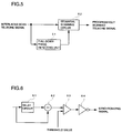
- Fig. 5 is a block diagram of the up-converter.
- the numeral 51 is a pull-down phase detecting unit for outputting a synchronizing signal corresponding to the pull-down phase.
- the numeral 52 is a sequential scanning circuit for converting an interlaced telecine signal into a progressively scanned signal based on the synchronizing signal.
- Fig. 6 is a detailed block diagram of the pull-down phase detecting unit.
- the numeral 61 is a delay circuit.
- the delay circuit 61 delays the input interlaced scan telecine signal by two fields.
- the numeral 62 is a subtraction unit.
- the subtraction unit 62 obtains a difference value by subtraction between an interlaced scan telecine signal and the interlaced signal delayed by two fields and output from the delay circuit 61. That is, a difference between a signal of a certain field signal and a signal of two fields before the certain field. The difference takes the value of a difference between each picture element of the two fields.
- the numeral 63 is a comparator.
- the comparator 63 compares an output signal (a difference value) of the subtraction unit 62 and a threshold predetermined setting and turn on when the difference is larger. In this case, the comparator turns on when five percent or larger of the picture elements comprise a difference value of the picture elements that is larger than five percent.
- the numeral 64 is a reverser for reversing and outputting an output from the comparator 63. Therefore, only when the comparator 63 is off, that is, the difference is smaller than the threshold, a synchronizing signal is output.
- the pull-down detecting unit 51 outputs a synchronizing signal synchronized with the pull-down phase.
- Fig. 7 is a detailed block diagram of the sequential scanning circuit 52 and Fig. 8 is a time chart of the sequential scanning circuit 52.
- the numeral 71 is a clock generation circuit.
- the clock generation circuit 71 inputs an interlaced scan telecine signal and generates a write clock synchronized with each picture element of the interlaced scan telecine signal.
- the numeral 72 is a clock frequency converter for doubling the rate of a clock generated with the clock generation circuit 71 and generating a read clock.
- the numeral 73 is a timing signal generation circuit.
- the timing signal generation circuit 73 generates write timing signals WR1, WR2 and read timing signals RD1, RD2 of field memories 74, 75, 76, 77 to be described later and an SEL signal for controlling the field memories 74, 75, 76, 77 based on a synchronizing signal between a clock of the clock generation circuit 71 and the pull-down phase detecting unit 51.
- the numerals 74, 75 are field memories for storing an odd field signal.
- an odd field signal among interlaced scan telecine signals is stored at the rate of the write clock according to the timing of the write timing signal WR1 and the SEL signal.
- Each odd scanning line stored at the rate of the read clock is then read according to the timing of the read timing signal RD1 and the SEL signal.
- the numerals 76 and 77 are field memories for storing an even field signal.
- an even field signal among interlaced telecine signals is stored at the rate of the write clock according to the timing of the write timing signal WR2 and the SEL signal.
- Each even scanning line stored at the rate of the read clock is then read according to the timing of the read timing signal RD2 and the SEL signal.
- the numerals 78a to 78t are AND circuits.
- the numerals 79a to 79j are reversers.
- the numerals 80a to 80d are tri-state buffers.
- the write timing signal WR1 and the SEL signal are set in a high level, therefore the odd scanning line signal A1 is written in the field memory 74.
- the write timing signal WR2 and the SEL signal are set in a high level, the even scanning line signal A2 written in the field memory 76.
- the write timing signal WR1 is set in a high level and the SEL signal is set in a low level. Therefore, the odd scanning line signal B1 is written in the field memory 75.
- the write timing signal WR2 is set in a high level and the SEL signal is set in a low level. Therefore, the even scanning line signal B2 is written in the field memory 77.
- the SEL signal is set in a low level, therefore the odd scanning line signal A1 written in the field memory 74 is read one by one at the doubled write rate according to the timing of the read timing signal RD1 and output from the tri-state buffer 80a.
- the SEL signal is set in a low level, therefore the even scanning line signal A2 written in the field memory 76 is read one by one at the doubled write rate according to the timing of the read timing signal RD2 and output from the tri-state buffer 80c.
- the progressively scanned telecine signal A generated by composing the odd scanning line signal A1 and the even scanning line signal A2 is output from the output terminal 81.
- the SEL signal is in a low level in two fields, therefore signals for two fields are output in sequence from the field memories 74 and 76.
- the progressively scanned telecine signal A is generated from the first and second frames.
- the SEL signal is in a high level from the fifth field, therefore the odd scanning line signal B1 written in the field memory 75 is read one by one at the doubled write rate according to the timing of the read timing signal RD1 and output from the tri-state buffer 80b.
- the even scanning line signal B2 written in the field memory 77 is read one by one at the doubled write rate according to the timing of the read timing signal RD2 and output from the tri-state buffer 80d.
- the progressively scanned telecine signal B generated by composing the odd scanning line signal B1 and the even scanning line signal B2 is output from the output terminal 81.
- the SEL signal is in a high level in three fields, therefore signals for three fields are read from the field memories 75 and 77.
- the progressively scanned telecine signal B is generated from the third, fourth and fifth frames.
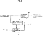
- Fig. 9 is a block diagram of the up-converter using a time code value.
- the numeral 91 is a time code comparison unit.
- the time code comparison unit 91 generates a synchronized stable synchronizing signal synchronized with the pull-down phase by using a synchronizing signal from the pull-down phase detecting unit 51.
- the numeral 92 is a switch for switching a synchronizing signal from the pull-down phase detecting unit 51 and a synchronizing signal from the time code comparison unit 91.
- the time code comparison unit 91 is explained in details as follows, referring to Fig. 10.
- the numeral 101 is a field pulse generation unit.
- the field pulse generation unit 101 inputs a time code signal of a interlaced scan telecine signal and generates a field pulse synchronized with the time code value, that is, synchronized with the field of the interlaced scan telecine signal.
- the numeral 102 is a comparison unit.
- the comparison unit 102 compares a time code value shown by the time code signal and a time code value predetermined setting and when the two values become the same, outputs a pulse.
- the numeral 103 is a counter.
- the counter 103 starts count operation by a pulse from the comparison unit 102 and counts a field pulse.
- the counter 103 then stops the count operation by a synchronizing signal from the pull-down phase detecting unit 51 and outputs the count value.
- the numeral 104 is a display unit.
- the display unit 104 displays a count value output from the counter 103.
- the displayed count value is the vale of the difference between the timing of the set time code value and the pull-down phase.
- the numeral 105 is a five counter.
- the five counter 105 starts operation by a pulse from the comparison unit 102 and counts a field pulse.
- the five counter 105 then outputs a pulse at intervals of five fields.
- the numeral 106 is a delay circuit.
- the delay circuit 106 delays a pulse by the set amount of the delay.
- a value displayed on the display unit 104 is set for the amount of the delay.
- the value three is specified here for a time code value to be set in the comparison unit 102.
- time code values 1, 2.... are input in sequence to the comparison unit 102.
- the comparison unit 102 outputs a pulse.
- the counter 103 then starts count operation and counts a field pulse. At this time, when the counter 103 counts the value two, a synchronizing signal from the pull-down phase detecting unit 51 is input.
- the counter 103 stops the count operation and outputs the count value to the display unit 104.
- the display unit 104 then displays the value two.
- the value two displayed on the display unit 104 is set in the delay circuit, that is, the delay amount of the delay circuit 106 becomes two.
- the five counter 105 starts count operation by a pulse from the comparison unit 102.
- Time code values 2, 3, 4, 5, 6 are then displayed in sequence and when the value five is counted, a pulse is output.
- the pulse from the five counter 105 is delayed by two fields with the delay circuit 106 and output.
- a pulse to be output from the delay circuit 106 becomes a signal synchronized with time code values 5, 10, 15...., that is, synchronized with the pull-down phase.
- the pull-down phase detecting unit 51 when used in a field where a pull-down phase is correctly detected in order to switch to a synchronizing signal synchronized with the time code value by the switch 92, even if a pull-down phase is not correctly detected, for example, a difference other than the difference between a signal of a present field and a signal of two fields before becomes zero like when frames of the same pictures are consecutive, a synchronizing signal synchronized with the pull-down phase is stably obtained.
- the display unit 104 displays the delay quantity and sets the delay quantity at the delay circuit 106, it is possible to omit the display unit 104, the delay quantity that has been displayed by the display unit 104 is automatically set at the delay circuit 106.
- an interlaced telecine signal can be converted into a progressively scanned telecine signal without the use of an expensive sequential scanning telecine unit.
Landscapes
- Engineering & Computer Science (AREA)
- Multimedia (AREA)
- Signal Processing (AREA)
- Television Systems (AREA)
- Studio Devices (AREA)
Applications Claiming Priority (2)
| Application Number | Priority Date | Filing Date | Title |
|---|---|---|---|
| JP340411/95 | 1995-12-27 | ||
| JP7340411A JP2906332B2 (ja) | 1995-12-27 | 1995-12-27 | テレシネ信号変換方法、及びアップコンバータ |
Publications (2)
| Publication Number | Publication Date |
|---|---|
| EP0782334A2 true EP0782334A2 (de) | 1997-07-02 |
| EP0782334A3 EP0782334A3 (de) | 1998-07-22 |
Family
ID=18336696
Family Applications (1)
| Application Number | Title | Priority Date | Filing Date |
|---|---|---|---|
| EP96309387A Withdrawn EP0782334A3 (de) | 1995-12-27 | 1996-12-20 | Fernsehfilmsignalumwandlungsmethode und Frequenzaufwärtswandler |
Country Status (4)
| Country | Link |
|---|---|
| US (1) | US6144410A (de) |
| EP (1) | EP0782334A3 (de) |
| JP (1) | JP2906332B2 (de) |
| CA (1) | CA2193768A1 (de) |
Cited By (5)
| Publication number | Priority date | Publication date | Assignee | Title |
|---|---|---|---|---|
| WO2000038419A1 (en) * | 1998-12-22 | 2000-06-29 | Matsushita Electric Industrial Co., Ltd. | Video signal reproducing device |
| US6385240B2 (en) | 1997-07-15 | 2002-05-07 | Matsushita Electric Industrial Co, Ltd. | Progressive image signal transmitter, progressive image signal receiver and, medium |
| EP1156675A3 (de) * | 2000-05-18 | 2007-12-05 | Pioneer Corporation | Bildanzeigevorrichtung |
| EP2136024A1 (de) | 2008-06-18 | 2009-12-23 | Technoform Caprano + Brunnhofer GmbH & Co. KG | Verbundprofil für Fenster-, Türen-, oder Fassadenelement mit vorbestimmten Brandschutzeigenschaften und Isoliersteg für ein Verbundprofil mit Brandschutzeigenschaften |
| DE19963041B4 (de) * | 1999-12-24 | 2011-03-31 | Bts Holding International B.V. | Schaltungsanordnung zum Erkennen von Filmquellen |
Families Citing this family (16)
| Publication number | Priority date | Publication date | Assignee | Title |
|---|---|---|---|---|
| US6166772A (en) * | 1997-04-01 | 2000-12-26 | Compaq Computer Corporation | Method and apparatus for display of interlaced images on non-interlaced display |
| JP3686249B2 (ja) * | 1998-03-20 | 2005-08-24 | パイオニア株式会社 | 重複画像検出装置、画像変換装置、重複画像検出方法及び画像変換方法並びに画像記録媒体 |
| EP1309193A4 (de) | 2000-08-10 | 2005-09-28 | Sony Corp | Verfahren und vorrichtung zur videosignalverarbeitung |
| US6839094B2 (en) * | 2000-12-14 | 2005-01-04 | Rgb Systems, Inc. | Method and apparatus for eliminating motion artifacts from video |
| WO2003015422A1 (en) * | 2001-07-10 | 2003-02-20 | Sony Corporation | Video signal judgment apparatus and method |
| JP4538174B2 (ja) * | 2001-08-31 | 2010-09-08 | パイオニア株式会社 | 映像信号のテレシネ変換方式検出装置 |
| KR100768579B1 (ko) | 2001-11-02 | 2007-10-18 | 마쯔시다덴기산교 가부시키가이샤 | 주사 변환 장치 |
| JP4090764B2 (ja) * | 2002-03-18 | 2008-05-28 | パイオニア株式会社 | 映像信号処理装置 |
| JP2003274370A (ja) * | 2002-03-19 | 2003-09-26 | Matsushita Electric Ind Co Ltd | タイムコード信号伝送方法およびタイムコード信号伝送装置 |
| TWI232681B (en) * | 2003-08-27 | 2005-05-11 | Mediatek Inc | Method of transforming one video output format into another video output format without degrading display quality |
| JP2005295134A (ja) * | 2004-03-31 | 2005-10-20 | Pioneer Electronic Corp | 適応型フレーム同期装置 |
| JP5002249B2 (ja) * | 2006-11-30 | 2012-08-15 | 株式会社東芝 | フレーム内挿装置及びフレーム内挿方法並びに画像表示装置 |
| JP2009060401A (ja) * | 2007-08-31 | 2009-03-19 | Sony Corp | 画像表示装置および画像処理装置 |
| US8462264B2 (en) | 2008-04-23 | 2013-06-11 | Panasonic Corporation | Video scan converter for performing interlaced to progressive scan conversion |
| JP5124008B2 (ja) * | 2010-11-29 | 2013-01-23 | Necパーソナルコンピュータ株式会社 | 画像表示方法及び画像表示装置並びにプログラム |
| CN103699886B (zh) * | 2013-12-19 | 2017-02-08 | 北京航天测控技术有限公司 | 一种视频实时比对方法 |
Family Cites Families (6)
| Publication number | Priority date | Publication date | Assignee | Title |
|---|---|---|---|---|
| DK0461209T3 (de) * | 1989-10-20 | 1997-02-17 | Snell & Wilcox Ltd | |
| US5355178A (en) * | 1991-10-24 | 1994-10-11 | Eastman Kodak Company | Mechanism for improving television display of still images using image motion-dependent filter |
| JPH0795441A (ja) * | 1993-09-20 | 1995-04-07 | Hitachi Ltd | テレビジョン信号処理方式 |
| GB9401897D0 (en) * | 1994-02-01 | 1994-03-30 | Snell & Wilcox Ltd | Video processing |
| JP2947400B2 (ja) * | 1994-05-31 | 1999-09-13 | 日本ビクター株式会社 | フレーム周波数変換装置 |
| US5661525A (en) * | 1995-03-27 | 1997-08-26 | Lucent Technologies Inc. | Method and apparatus for converting an interlaced video frame sequence into a progressively-scanned sequence |
-
1995
- 1995-12-27 JP JP7340411A patent/JP2906332B2/ja not_active Expired - Fee Related
-
1996
- 1996-12-20 US US08/770,833 patent/US6144410A/en not_active Expired - Fee Related
- 1996-12-20 EP EP96309387A patent/EP0782334A3/de not_active Withdrawn
- 1996-12-23 CA CA2193768A patent/CA2193768A1/en not_active Abandoned
Non-Patent Citations (1)
| Title |
|---|
| WOO PAIK: "DigicipherTM- all digital, channel compatible, HDTV broadcast system", IEEE TRANSACTIONS ON BROADCASTING, vol. 36, no. 4, December 1990 (1990-12-01), NEW-YORK, pages 245 - 254, XP000179349, DOI: doi:10.1109/11.64474 * |
Cited By (9)
| Publication number | Priority date | Publication date | Assignee | Title |
|---|---|---|---|---|
| US6385240B2 (en) | 1997-07-15 | 2002-05-07 | Matsushita Electric Industrial Co, Ltd. | Progressive image signal transmitter, progressive image signal receiver and, medium |
| EP0933942A4 (de) * | 1997-07-15 | 2004-04-21 | Matsushita Electric Industrial Co Ltd | Überträger, empfänger und medium für progressives bildsignal |
| WO2000038419A1 (en) * | 1998-12-22 | 2000-06-29 | Matsushita Electric Industrial Co., Ltd. | Video signal reproducing device |
| KR100614788B1 (ko) * | 1998-12-22 | 2006-08-25 | 마쯔시다덴기산교 가부시키가이샤 | 영상 신호 재생 장치 |
| US7269342B1 (en) | 1998-12-22 | 2007-09-11 | Matsushita Electric Industrial Co., Ltd. | Video signal reproducing device |
| US7536089B2 (en) | 1998-12-22 | 2009-05-19 | Panasonic Corporation | Image signal reproduction apparatus |
| DE19963041B4 (de) * | 1999-12-24 | 2011-03-31 | Bts Holding International B.V. | Schaltungsanordnung zum Erkennen von Filmquellen |
| EP1156675A3 (de) * | 2000-05-18 | 2007-12-05 | Pioneer Corporation | Bildanzeigevorrichtung |
| EP2136024A1 (de) | 2008-06-18 | 2009-12-23 | Technoform Caprano + Brunnhofer GmbH & Co. KG | Verbundprofil für Fenster-, Türen-, oder Fassadenelement mit vorbestimmten Brandschutzeigenschaften und Isoliersteg für ein Verbundprofil mit Brandschutzeigenschaften |
Also Published As
| Publication number | Publication date |
|---|---|
| JP2906332B2 (ja) | 1999-06-21 |
| CA2193768A1 (en) | 1997-06-27 |
| US6144410A (en) | 2000-11-07 |
| JPH09181967A (ja) | 1997-07-11 |
| EP0782334A3 (de) | 1998-07-22 |
Similar Documents
| Publication | Publication Date | Title |
|---|---|---|
| US6144410A (en) | Telecine signal conversion method and an up-converter | |
| US6317165B1 (en) | System and method for selective capture of video frames | |
| EP0948863B1 (de) | Vorrichtung zum empfangen, anzeigen und gleichzeitigem aufzeichnen von fernsehbildern via einem pufferspeicher | |
| EP1056285A2 (de) | Videoanzeigegerät zum Anzeigen von Videosignalen nach mehreren Arten mit verschiedenen Spezifikationen | |
| EP0249281B1 (de) | Fernsehbildwiedergabevorrichtung | |
| EP0167343B1 (de) | Zeilenfolgeabtastungs-Fernsehempfänger mit adaptischer Speicheradressierung | |
| US6297850B1 (en) | Sync signal generating apparatus and method for a video signal processor | |
| CA2328951C (en) | Image signal processing device | |
| EP0392618B1 (de) | Einrichtung zur Erzeugung eines Horizontalrückstellsignals, synchron mit einem hilfsträgerverriegelten Taktsignal | |
| KR0167799B1 (ko) | 영상신호압축장치 | |
| EP0746154B1 (de) | Schaltung zur vertikalen Kompression eines Kleinbildsignals | |
| US5493589A (en) | Circuit arrangement for synchronizing a data stream | |
| EP0585903B1 (de) | Speichervorrichtung für Videosignal | |
| US7139030B2 (en) | Video signal processing apparatus | |
| US5724476A (en) | Method and apparatus for extending and reproducing compressed moving pictures | |
| KR100279167B1 (ko) | 양호한노이즈면역성을갖는tv라인및필드검출장치 | |
| US4903127A (en) | Field generator with incomplete line correction | |
| US6819363B2 (en) | Video signal processing device | |
| JP3091293B2 (ja) | 映像再生速度変換装置 | |
| JP3480573B2 (ja) | ビデオ信号処理装置 | |
| EP1156675A2 (de) | Bildanzeigevorrichtung | |
| KR970011510B1 (ko) | 비월된 신호의 처리장치 및 선택기 신호 발생 방법 | |
| JP3184051B2 (ja) | 時間軸補正回路 | |
| JPH05183807A (ja) | 映像信号伝送装置 | |
| JPS61192185A (ja) | 2画面テレビ受信機 |
Legal Events
| Date | Code | Title | Description |
|---|---|---|---|
| PUAI | Public reference made under article 153(3) epc to a published international application that has entered the european phase |
Free format text: ORIGINAL CODE: 0009012 |
|
| AK | Designated contracting states |
Kind code of ref document: A2 Designated state(s): DE FR GB NL |
|
| PUAL | Search report despatched |
Free format text: ORIGINAL CODE: 0009013 |
|
| AK | Designated contracting states |
Kind code of ref document: A3 Designated state(s): DE FR GB NL |
|
| 17P | Request for examination filed |
Effective date: 19980916 |
|
| 17Q | First examination report despatched |
Effective date: 20011015 |
|
| STAA | Information on the status of an ep patent application or granted ep patent |
Free format text: STATUS: THE APPLICATION IS DEEMED TO BE WITHDRAWN |
|
| 18D | Application deemed to be withdrawn |
Effective date: 20030507 |