EP0782671B1 - DISPOSITIF POUR l'ENTREINEMENT CONTROLE D'AU MOINS UN ARBRE HYDRAULIQUE - Google Patents
DISPOSITIF POUR l'ENTREINEMENT CONTROLE D'AU MOINS UN ARBRE HYDRAULIQUE Download PDFInfo
- Publication number
- EP0782671B1 EP0782671B1 EP96913422A EP96913422A EP0782671B1 EP 0782671 B1 EP0782671 B1 EP 0782671B1 EP 96913422 A EP96913422 A EP 96913422A EP 96913422 A EP96913422 A EP 96913422A EP 0782671 B1 EP0782671 B1 EP 0782671B1
- Authority
- EP
- European Patent Office
- Prior art keywords
- hydraulic
- pump
- pressure
- control
- drive
- Prior art date
- Legal status (The legal status is an assumption and is not a legal conclusion. Google has not performed a legal analysis and makes no representation as to the accuracy of the status listed.)
- Expired - Lifetime
Links
Images


Classifications
-
- B—PERFORMING OPERATIONS; TRANSPORTING
- B29—WORKING OF PLASTICS; WORKING OF SUBSTANCES IN A PLASTIC STATE IN GENERAL
- B29C—SHAPING OR JOINING OF PLASTICS; SHAPING OF MATERIAL IN A PLASTIC STATE, NOT OTHERWISE PROVIDED FOR; AFTER-TREATMENT OF THE SHAPED PRODUCTS, e.g. REPAIRING
- B29C45/00—Injection moulding, i.e. forcing the required volume of moulding material through a nozzle into a closed mould; Apparatus therefor
- B29C45/17—Component parts, details or accessories; Auxiliary operations
- B29C45/76—Measuring, controlling or regulating
- B29C45/82—Hydraulic or pneumatic circuits
-
- B—PERFORMING OPERATIONS; TRANSPORTING
- B30—PRESSES
- B30B—PRESSES IN GENERAL
- B30B15/00—Details of, or accessories for, presses; Auxiliary measures in connection with pressing
- B30B15/16—Control arrangements for fluid-driven presses
- B30B15/166—Electrical control arrangements
-
- F—MECHANICAL ENGINEERING; LIGHTING; HEATING; WEAPONS; BLASTING
- F04—POSITIVE - DISPLACEMENT MACHINES FOR LIQUIDS; PUMPS FOR LIQUIDS OR ELASTIC FLUIDS
- F04B—POSITIVE-DISPLACEMENT MACHINES FOR LIQUIDS; PUMPS
- F04B49/00—Control, e.g. of pump delivery, or pump pressure of, or safety measures for, machines, pumps, or pumping installations, not otherwise provided for, or of interest apart from, groups F04B1/00 - F04B47/00
- F04B49/06—Control using electricity
- F04B49/065—Control using electricity and making use of computers
-
- B—PERFORMING OPERATIONS; TRANSPORTING
- B29—WORKING OF PLASTICS; WORKING OF SUBSTANCES IN A PLASTIC STATE IN GENERAL
- B29C—SHAPING OR JOINING OF PLASTICS; SHAPING OF MATERIAL IN A PLASTIC STATE, NOT OTHERWISE PROVIDED FOR; AFTER-TREATMENT OF THE SHAPED PRODUCTS, e.g. REPAIRING
- B29C45/00—Injection moulding, i.e. forcing the required volume of moulding material through a nozzle into a closed mould; Apparatus therefor
- B29C45/17—Component parts, details or accessories; Auxiliary operations
- B29C2045/1784—Component parts, details or accessories not otherwise provided for; Auxiliary operations not otherwise provided for
- B29C2045/1792—Machine parts driven by an electric motor, e.g. electric servomotor
-
- B—PERFORMING OPERATIONS; TRANSPORTING
- B29—WORKING OF PLASTICS; WORKING OF SUBSTANCES IN A PLASTIC STATE IN GENERAL
- B29C—SHAPING OR JOINING OF PLASTICS; SHAPING OF MATERIAL IN A PLASTIC STATE, NOT OTHERWISE PROVIDED FOR; AFTER-TREATMENT OF THE SHAPED PRODUCTS, e.g. REPAIRING
- B29C45/00—Injection moulding, i.e. forcing the required volume of moulding material through a nozzle into a closed mould; Apparatus therefor
- B29C45/17—Component parts, details or accessories; Auxiliary operations
- B29C45/76—Measuring, controlling or regulating
- B29C45/7666—Measuring, controlling or regulating of power or energy, e.g. integral function of force
- B29C2045/7673—Recovering energy or power from drive motors
-
- B—PERFORMING OPERATIONS; TRANSPORTING
- B29—WORKING OF PLASTICS; WORKING OF SUBSTANCES IN A PLASTIC STATE IN GENERAL
- B29C—SHAPING OR JOINING OF PLASTICS; SHAPING OF MATERIAL IN A PLASTIC STATE, NOT OTHERWISE PROVIDED FOR; AFTER-TREATMENT OF THE SHAPED PRODUCTS, e.g. REPAIRING
- B29C45/00—Injection moulding, i.e. forcing the required volume of moulding material through a nozzle into a closed mould; Apparatus therefor
- B29C45/17—Component parts, details or accessories; Auxiliary operations
- B29C45/76—Measuring, controlling or regulating
- B29C45/82—Hydraulic or pneumatic circuits
- B29C2045/824—Accumulators
-
- B—PERFORMING OPERATIONS; TRANSPORTING
- B29—WORKING OF PLASTICS; WORKING OF SUBSTANCES IN A PLASTIC STATE IN GENERAL
- B29C—SHAPING OR JOINING OF PLASTICS; SHAPING OF MATERIAL IN A PLASTIC STATE, NOT OTHERWISE PROVIDED FOR; AFTER-TREATMENT OF THE SHAPED PRODUCTS, e.g. REPAIRING
- B29C45/00—Injection moulding, i.e. forcing the required volume of moulding material through a nozzle into a closed mould; Apparatus therefor
- B29C45/17—Component parts, details or accessories; Auxiliary operations
- B29C45/40—Removing or ejecting moulded articles
- B29C45/4005—Ejector constructions; Ejector operating mechanisms
-
- B—PERFORMING OPERATIONS; TRANSPORTING
- B29—WORKING OF PLASTICS; WORKING OF SUBSTANCES IN A PLASTIC STATE IN GENERAL
- B29C—SHAPING OR JOINING OF PLASTICS; SHAPING OF MATERIAL IN A PLASTIC STATE, NOT OTHERWISE PROVIDED FOR; AFTER-TREATMENT OF THE SHAPED PRODUCTS, e.g. REPAIRING
- B29C45/00—Injection moulding, i.e. forcing the required volume of moulding material through a nozzle into a closed mould; Apparatus therefor
- B29C45/17—Component parts, details or accessories; Auxiliary operations
- B29C45/46—Means for plasticising or homogenising the moulding material or forcing it into the mould
- B29C45/47—Means for plasticising or homogenising the moulding material or forcing it into the mould using screws
- B29C45/50—Axially movable screw
- B29C45/5008—Drive means therefor
-
- B—PERFORMING OPERATIONS; TRANSPORTING
- B29—WORKING OF PLASTICS; WORKING OF SUBSTANCES IN A PLASTIC STATE IN GENERAL
- B29C—SHAPING OR JOINING OF PLASTICS; SHAPING OF MATERIAL IN A PLASTIC STATE, NOT OTHERWISE PROVIDED FOR; AFTER-TREATMENT OF THE SHAPED PRODUCTS, e.g. REPAIRING
- B29C45/00—Injection moulding, i.e. forcing the required volume of moulding material through a nozzle into a closed mould; Apparatus therefor
- B29C45/17—Component parts, details or accessories; Auxiliary operations
- B29C45/64—Mould opening, closing or clamping devices
- B29C45/68—Mould opening, closing or clamping devices hydro-mechanical
-
- Y—GENERAL TAGGING OF NEW TECHNOLOGICAL DEVELOPMENTS; GENERAL TAGGING OF CROSS-SECTIONAL TECHNOLOGIES SPANNING OVER SEVERAL SECTIONS OF THE IPC; TECHNICAL SUBJECTS COVERED BY FORMER USPC CROSS-REFERENCE ART COLLECTIONS [XRACs] AND DIGESTS
- Y02—TECHNOLOGIES OR APPLICATIONS FOR MITIGATION OR ADAPTATION AGAINST CLIMATE CHANGE
- Y02P—CLIMATE CHANGE MITIGATION TECHNOLOGIES IN THE PRODUCTION OR PROCESSING OF GOODS
- Y02P70/00—Climate change mitigation technologies in the production process for final industrial or consumer products
- Y02P70/10—Greenhouse gas [GHG] capture, material saving, heat recovery or other energy efficient measures, e.g. motor control, characterised by manufacturing processes, e.g. for rolling metal or metal working
Definitions
- the invention relates to a device for the controlled drive of at least one hydraulic machine axis, at least one hydraulic actuator via a hydraulic line connected to a hydraulic pump and the hydraulic pump is driven by a variable-speed drive motor, which is controlled by a tax / regulatory intelligence.
- Machine builders use adjustable drives with which the mechanical sizes (Force and / or position) individual axes or degrees of freedom of the machine can be.
- the focus is on electrical and hydraulic drives.
- Electromotive control drives are involved in converting the rotary movement into one linear movement at a disadvantage, especially with large transmission forces.
- the big disadvantage The hydraulic drives have so far been based on energy efficiency. A typical one An example of this dispute can be seen in the injection molding machine market. Companies with electrotechnical background try to market an "all electric” machine bring, the competition defends itself with “all hydraulic”. Both have good arguments her side. If you analyze the advantages and disadvantages of the two technologies impartially, so there are considerable differences.
- DE-PS No. 4 303 760 shows a hydraulic drive with an open hydraulic circuit.
- the pump conveys the medium via a pressure control device, which consists of a pressure relief valve and a pressure control valve as a pilot valve (electrical controlled proportional pressure adjustment valve).
- the pilot valve is over a Signal line controlled by an intelligence or a computer. Between valve and Working cylinder with the axis or mass to be moved is a path logic. This is also controlled electrically by the computer.
- the actual regulation takes place by processing both a speed and a path signal and the like Actual value / setpoint comparison in the computer and appropriate control of the valve group instead.
- the control / regulation takes place with an open hydraulic Drive via intelligent valves.
- EPA 643 472 shows one so-called intelligent drive for an electric motor drive of one or more Axes. Both solutions lead to the goal, namely the mastery of the control processes to a higher degree and have practical experience on the same machine rendered. Proof has been furnished that a fully electric injection molding machine according to WO94 / 22655 only 20 to 30% of the drive energy of the corresponding hydraulic machine of the prior art.
- EP publications 649 723, EP 468 286, EP 574 623 and DE 195 24 395 and DE 43 35 403 each have one hydraulic operating system with dissipation. It takes place in the dynamic Operations hydraulic control of performance with valves with valves instead. P / Q will calculated and controlled according to the machine program.
- the object of the invention was now to create a new, highly dynamic and, if possible to develop a generally usable drive concept that takes advantage of the open hydraulic and electric drive combined as much as possible, and the avoids respective disadvantages.
- An optimization of the "interface" between the two wanted, especially for drives with motion cycles within seconds, i.e. especially with high accelerations / decelerations.
- the solution according to the invention is characterized in that the control of the Power of the at least one hydraulic machine axis through power electronics Actuators that the pressure in the actuator or in the hydraulic line in this Control / regulation flows in, and that when the axis reverses motion or at Pressure reduction a change of direction in the hydraulic pump, but not a Load change takes place in the hydraulic pump.
- the new invention allows a number of particularly advantageous configurations. It reference is made to claims 2 to 13.
- the pump is preferably designed as a hydraulic internal gear pump.
- Internal gear pumps have favorable kinematics, which only lead to low fluid accelerations in the intake, which justifies the good suction properties and the great freedom from cavitation.
- the pump is equipped with a hydraulic actuator e.g. connected to a cylinder or a hydraulic motor, and sucks the working fluid directly from a tank, the latter a feature of an open hydraulic system. It was recognized by the inventors that with very dynamic electric motors such as e.g. a servo motor, in the suction line a high vacuum is created by the acceleration of the fluid column. If the requirements are high, pumps must be used which have good suction power and can withstand variable-speed operation even at high pressures.
- the drive according to the invention is outstandingly suitable as a 4-quadrant drive for drive tasks in the first and second quadrants, ie where forces have to be regulated in only one direction.
- a potential is applied to the opposite hydraulic side. This can e.g. by a pressure accumulator, a spring or a mass which is exposed to a gravitational field.
- the derivation of the potential according to the path defines a force that enables the new drive to be controlled in the other direction of movement, that is to say in quadrants three and four.
- the electric motor / pump system not only works against external forces when moving in the positive direction, but also against the potential forces at the same time.
- the additional work performed will be stored as potential energy and is available when moving in the negative direction.
- a special feature of this drive is that the pump itself only works in two-quadrant mode. There is a change in the direction of rotation, but not a load change in the hydraulic pump or in the coupling between the motor and pump. This is important for control-technical reasons, because otherwise there is an inconsistency with every load change, which can be very disruptive (hysteresis in the position sizes).
- the new solution is a 4-quadrant drive made up of electrical and hydraulic elements for controlling and regulating one or more axes of machines.
- the drive can be controlled / regulated in all four quadrants, that is to say that the drive can impart mechanical variables in both directions of rotation of the driven machines, in particular forces, moments, positions, angles of rotation, position Force relationships (characteristics) or time derivatives of these quantities.
- the hydraulic circuit has an actuator, the opposite side of which is pressurized with an energy store (or a potential) which can be operated as a spring store.
- actuators can also be connected to a common energy store via an energy storage network.
- more than one axis can be driven via the hydraulically open circuit, at least one or more or all of the axes also being able to be operated without a control valve.
- the new solution allows completely new combinations, e.g. in that the power of a regulated power unit is switched over to several actuators in an electrical, mechanical or hydraulic manner.
- Several drive axes or Degrees of freedom can be supplied with just one controllable power unit (actuator).
- At least one safety valve can be arranged in the hydraulically open circuit as a switching valve, or as a pressure limiting or emergency shutoff valve.
- the force on the actuator can be measured, stored, and a tolerance band can be defined for controlling or monitoring the actuator via the hydraulic pressure or the motor current consumption, the actuator being stopped and / or reversed when the tolerance band is exceeded in the active actuator movement.
- the inventors set themselves the task of taking the best of hydraulics and electromechanics, as it were, and combining them in a so-called electrohydraulic drive, which allows mechanical power to be controlled and regulated with little loss, and to recuperate the energy introduced. The aim was that the power and performance concentration, robustness and cost advantages correspond to the properties of the hydraulic drive.
- the device permits the construction of a hybrid drive system in which at least one preferably linearly moving axis is hydraulically free of dissipation and at least one further axis can be driven or moved by means of an electric motor and / or conventional valve control via the power electronic elements and a process computer.
- the device is designed as a hybrid drive system, with at least one, preferably linearly moving axis being hydraulically free of dissipation via the corresponding control computer intelligence and at least one further axis being able to be driven or moved by an electric motor via the power electronic elements and a process computer is. This allows several axes to be controlled and regulated sequentially independently via the hydraulic system and one or more electromotive axes via the same control / regulating intelligence.
- the machine can be qualitatively upgraded to a higher level with only one control system or only one control philosophy for the system part in question.
- the hydraulic medium loses its previous function as a fluid pressure regulator and becomes an approximately rigid hydraulic transmission that can be guided around all corners.
- All rotating axes are driven by an electric motor and all linearly moving axes are driven by the hydraulic medium.
- the device is designed as a robot / machine tool, in particular as an injection molding machine as a die casting machine, as a press, as a test machine or as a steward platform (all of which have highly dynamic movement sequences), one or more axes being designed as a hydraulically moved axis.
- the device can be designed as a casting machine in such a way that the hydraulic drive system is designed for the mold movement and generation of the mold clamping force.
- the device can be designed as a casting machine, the process computer for sequential control / regulation of the hydraulic drive, for example.
- the axes are designed for clamping and / or injection and / or screw rotation.
- the process computer is designed as a multi-axis drive computer for controlling / regulating further servomotors for an electromechanical drive of unit displacements and / or ejectors and / or screw rotation and / or injection.
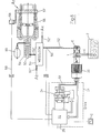
- a hydraulic pump 1 sucks a hydraulic medium from a tank 2 3 e.g. Oil via a suction line 4, and outputs via a pressure connection 5 and a pressure line 6 from the pressure medium 3 to an axis 7.
- Axis 7 represents one simple actuator with a simple hydraulic cylinder 8, with a piston 9 and one Piston rod 10 and is on a hinge 11 and a support plate 12 on an apparatus or machine part or base 13 supported.
- the piston rod 10 is directly with a element to be moved respectively Working element 14 connected.
- the pump-side pressure medium 15 is a compressible back pressure medium 16 e.g.
- Knitting gas opposite that in the example as a preferred solution via an exchange line 17 into a battery 18 can expand.
- the hydraulic pump 1 is driven by a drive motor 20, the mechanically directly via a coupling 19 with the corresponding drive axle Pump 1 is connected.
- 1 'is a dot-dash line designating a pressure generator as a whole, how it is designed to function according to the prior art.
- 20 With 20 'is the dash-dot Pump drive with adjustment and the associated functional elements.
- the dash-dotted box 21 contains the power electronic actuators 24 and the Control regulation intelligence, the current conversion and / or energy storage unit, which in Box 22 are subsumed.
- the conversion of alternating current from the electrical Grid in direct current is carried out according to a known method.
- the Control intelligence controls a network of power transistors. Via signal lines 23 is the input / output of the manipulated and measured variables such as e.g. Angle of rotation, Speed, currents or voltages on the motor. With C an input / output is indicated, the as a computer e.g. can be designed as a PC. In the example shown, it finds one multiple energy conversion instead. First of all, the power supply port 25 (as AC) converted to DC. Via the power electronic elements 24 According to the regulations, the electromagnetic ones are essentially simultaneous Generated fields in the drive motor.
- FIG. 2 shows a simplified example of an open hydraulic control of the State of the art.
- the pressure for example brought to 120 bar, is effectively over Throttles (control valves) reduced to 50 bar.
- Figure 3 shows an example of the new one Solution without a control valve, i.e. without a control valve.
- the power regulation can be found here in full the electrical side instead. This system is therefore completely free of dissipation.
- Figure 3a are force and pressure over the path for the solution according to the invention and in Figure 2a State of the art compared.
- the curve Sth is for the state of the art and the curve Eh for the new invention.
- the high level is clearly evident in the state of the art Loss work required to move back and forth (represented by 2 x 120 bar).
- FIG. 5 shows the control concept of the Servo pump controller represents.
- the pressure control of the servo pump controller is divided into three control loops nested in cascades ( Figure 5).
- the central hardware unit consists of the axis drive (A-Drive) and includes the two inner circles of the torque and Speed control (RN, RMd).
- the speed control (RN) is the torque control (RMd) overriding.
- the digital control signal is sent to the input of the torque control unit from the higher-level speed controller according to the motor angle (commutation) in divided two digital current control signals, and the two pulse width modulated Current control loops supplied.
- the outside as mentioned, is also in the drive Engine speed control is implemented digitally as a PID controller.
- This controller receives the setpoint from the superordinate pressure control module, which transmits a digital signal in revolutions per Minute delivers.
- the actual speed value is determined by subtraction of the resolver signal formed according to the absolute electrical motor angle. This route is scanned with e.g. 3 kHz.
- the new solution at least if some further development ideas are included all important ones Combine the advantages of electric and hydraulic drives.
- On the electrical / electronic side consist of the following basic elements Machine computer 30, a command device 31, a data bus 32, sensors or Sensor connections 33, a controller 34, a control / regulating unit 35, a drive computer 36 with the controller Re, a drive intelligence 37, a map / recipe memory 38 with a Control unit 40, which together form a multi-size process controller 39. It managed to create a drive that has the properties of electrical and hydraulic Drive combined in such a way that a new dynamic four-quadrant drive is created. This new combination offers new properties. From the hydraulic drives The new solution allows the following advantages in particular:
- High power concentration power per volume or power per weight of the actuator
- high power resp. Moment concentration force per volume and / or per weight of the Actuator
- small installation volume high mechanical efficiency for drives where relative small powers have to be applied with large forces or moments (high Reduction ratios in mechanical gears are lossy); inexpensive and simple switching of high performance by switching valves; the size of pressure and therefore also the force (force control) can be measured robustly and precisely with inexpensive sensors. Regardless of the size or power of the drive, the same sensors can always be used be used because the typical pressures are always the same.
- FIG. 5a The applicant has recognized that the disruptive low natural frequencies can be completely eliminated if the new one Solution instead of the manipulated variable volume flow, the controlled pressure used as the manipulated variable is used to control the speed (see also DE-PS No. 43 03 760).
- the controlled axis is u. a.
- FIG. 8 shows a basic concept of the new invention for the mold movement.
- the hydraulic drive system has a pump, a servo motor with drive and a drive computer with higher level intelligence or storage and any bus connections.
- a pressure sensor 50 represents a pressure control unit 51 due to the corresponding signal processing with a drive computer drive servo motor.
- the oil is fed to a hydraulic cylinder 54 via a pressure line 52 and a path logic 53.
- a piston rod 55 is held or moved in the hydraulic cylinder 54 and accordingly engages a closing unit 56 for a mold 57.
- the position or distance and speed can be transmitted to the drive computer via a position sensor 58 and signal line 59. E.g. for multi-size control of the corresponding moving part. Together with a back pressure unit 60, the resulting acceleration pressure is determined in particular as a manipulated variable.
- the clamping unit can be any casting machine such as an injection or die casting machine or e.g. also be blowing machine.
- pressure and the position of the moving machine are recorded as hydraulic variables and supplied to the control / regulating intelligence.
- a path logic enables the hydraulic power to be supplied to several specially operated hydraulic actuators. Measurement data of the control / regulation intelligence can be tracked on a PC, or motion programs for one or more axes can be downloaded to the control / regulation intelligence.
- FIG. 8 shows very clearly that one of the greatest advantages of the new invention is that a hydraulic drive can be used in an open circuit. You only need a control control intelligence, a pump and a drive motor. However, a whole number of sequentially operated axes A 1 , A 2 ... A x are operated via a pressure line network 52 ', 52 ", 52"'. With all the advantages that the compact on-site hydraulic cylinder or motor now has. The power is transmitted one after the other via the path logic.
- FIG. 9 shows an injection screw via a hydraulic cylinder 70 analogously to FIG 71 moved or held linearly. The rotational movement takes place via a Hydraulic motor 72.
- a pressure unit is designated 73 and a battery 74. With shown use of a battery 74 can axes, with only one motor at the same time operate.
- Figure 9 shows a drive solution in which because of very high Requirements for the dynamics of an axis using a dissipative servo valve can be.
- This conventional hydraulic with a pressure accumulator Circuit can now be controlled with a drive according to the invention via a path logic resp. be supplied with energy.
- FIG. 10 schematically shows a hybrid solution as a mixed electromotive-hydraulic driven machine.
- FIG. 10 shows another servo motor 80 for the Rotational movement of the injection screw 71 shown.
- the servomotor 80 is over the Signal line 81 controlled / regulated by the drive computer.
- Figure 10 shows to some extent a combined electromechanical-hydraulic drive system. However, it can any combination can be chosen. Which axis hydraulic and which Electromechanically driven, depends on the specific Framework. This concept also allows existing hydraulic machines possibly convert gradually to electromechanical drives.
- FIG. 11 is a steward platform 90 shows, which is movable over six controllable axes 91 to 96.
- Figure 11 shows one special case of a robot solution like e.g. can be used for simulators.
- a drive according to the invention is used as the drive solution.
- a single electrical energy storage / energy source is above one DC bus available to all drives.
- the data connection is not shown under the control of each drive. It allows synchronization and Coordination of the movements of all connected axes. All axes work According to the invention on a common pressure storage network, which all axes impresses repulsive or repelling potential forces.
- the suction lines of the Pumps can be operated via a common suction power (not shown).
- all of the required sensor / actuator data of the drive can be transmitted via one Fieldbus which are supplied to the axis computers, respectively. From the axis computers to the Peripherals are sent (e.g. for the calibration of sensors).
- Such measurement data can e.g. be: pressures, extension positions of the cylinder speeds of the variable-speed motors or temperatures in the system.
Landscapes
- Engineering & Computer Science (AREA)
- Mechanical Engineering (AREA)
- Manufacturing & Machinery (AREA)
- Computer Hardware Design (AREA)
- General Engineering & Computer Science (AREA)
- Fluid-Pressure Circuits (AREA)
- Engine Equipment That Uses Special Cycles (AREA)
- Vehicle Body Suspensions (AREA)
- Valve Device For Special Equipments (AREA)
- Control Of Positive-Displacement Pumps (AREA)
- Rotary Pumps (AREA)
- Motor Power Transmission Devices (AREA)
Claims (13)
- Dispositif pour l'entraínement contrôlé d'au moins un arbre hydraulique (A', A", Ax, 7, 91, 96), au moins un actionneur hydraulique (7) étant raccordé au moyen d'une conduite hydraulique (6) à une pompe hydraulique (1) et la pompe hydraulique (1) est entraínée par un moteur d'entraínement à régime variable (20), lequel est excité par une intelligence de commande/réglage, caractérisé en ce que le/la commande/réglage de la performance du au moins un arbre hydraulique s'effectue au moyen d'organes de réglage d'électronique de puissance (24), en ce que la pression se répand dans l'actionneur (7, 91 à 96) ou dans la conduite hydraulique (6, 52, 52', 52") à l'aide de ce/cette commande/réglage, et en ce que, lors de l'inversion de mouvement de l'arbre (A', A", Ax, 7, 91 à 96) ou lors de la réduction de pression, il se produit une modification du sens de rotation dans la pompe hydraulique (1) et non pas une alternance d'effort dans la pompe hydraulique (1).
- Dispositif selon la revendication 1, caractérisé en ce qu'il présente une pompe à volume constant, l'entraínement de pompe (20') s'effectuant au moyen d'un servomoteur (20) et le/la commande/réglage du régime et de la vitesse de régime s'effectuent au moyen d'un ordinateur industriel (C/22, 30, 31) et le circuit ouvert par voie hydraulique est configuré sans soupape de réglage et au moins un arbre hydraulique (A', A", Ax, 7, 91 à 96) est configuré comme arbre mobile de manière linéaire (A', A", Ax).
- Dispositif selon l'une des revendications 1 ou 2, caractérisé en ce que l'intelligence de commande/réglage présente un/une ordinateur/mémoire (30, 31, 34 à 38), où les paramètres de la pompe (1) (en particulier le courant de fuite de la mécanique des fluides comme fonction du régime, de la pression et de la température) peuvent être placés dans un/une ordinateur/mémoire et où ils peuvent être efficacement utilisés comme compensation des champs caractéristiques dans le réglage du régime du moteur d'entraínement.
- Dispositif selon l'une des revendications 1 à 3, caractérisé en ce qu'il présente une pompe à engrenages intérieurs et est configuré comme un entraínement à 4 ou 2 quadrants.
- Dispositif selon l'une des revendications 1 à 4, caractérisé en ce que le circuit hydraulique est équipé d'un actionneur (7), dont le côté de contre-pression présente un accumulateur d'énergie (ou un potentiel d'énergie) en particulier un accumulateur (18), qui peut être utilisé comme ressort accumulateur.
- Dispositif selon l'une des revendications 1 à 5, caractérisé en ce que plus d'un arbre (A, A", Ax, 7, 91 à 96) peuvent être entraínés au moyen d'un circuit ouvert par voie hydraulique, au moins un ou plusieurs ou la totalité des arbres (A', A", Ax, 7, 91 à 96) peuvent être actionnés sans soupape de réglage et/ou plusieurs actionneurs disposent d'un réseau de contre-pression commun.
- Dispositif selon l'une des revendications 1 à 6, caractérisé en ce que dans le circuit ouvert par voie hydraulique est agencée une soupape de sécurité qui est formée comme une soupape de commutation ou comme soupape de limitation de pression ou d'interruption d'urgence et/ou en ce que la force exercée sur l'actionneur est mesurée, mémorisée au moyen de la pression hydraulique ou en relevant le courant de moteur, et ainsi on peut déterminer une plage de tolérances, pour la commande ou la surveillance de l'actionneur, le dépassement de la plage de tolérances dans le mouvement actif de l'acteur proprement dit s'arrête et/ou est inversé.
- Dispositif selon l'une des revendications 1 à 7, caractérisé en ce qu'il est configuré comme un système d'entraínement hybride, dans lequel, au moyen d'éléments d'électronique de puissance tels qu'un ordinateur industriel, au moins un arbre (7), de préférence actionné de manière linéaire peut être entraíné ou déplacé hydrauliquement et au moins un autre arbre (72) peut être entraíné ou déplacé par un moteur électrique et/ou réglé par soupape de manière classique et/ou plusieurs arbres peuvent être commandés/réglés séquentiellement au moyen d'une intelligence de commande/réglage à l'aide du système hydraulique sans soupape de réglage et de plus un ou plusieurs arbres électromoteurs peuvent être commandés/réglés sans tenir compte du temps.
- Dispositif selon l'une des revendications 1 à 8, caractérisé en ce que l'entraínement électromoteur (20) peut être un servomoteur excité en permanence, un moteur asynchrone réglé de manière vectorielle, un moteur de courant continu réglé, un moteur à courant continu sans suramplifcation brusque ou un moteur à réluctance commuté ou un moteur piloté en fréquence.
- Dispositif selon l'une des revendications 1 à 9, caractérisé en ce qu'il est configuré comme un robot, comme une machine-outil, en particulier comme une machine à injection, comme machine à couler sous pression, comme presse, comme machine d'essai ou comme plate-forme principale, dans lequel le au moins un ou plusieurs arbres sont configurés sans dissipation comme des arbres mobiles hydrauliquement dans le circuit ouvert.
- Dispositif selon l'une des revendications 1 à 10, caractérisé en ce qu'il est configuré comme une machine à couler, où pour un ou plusieurs arbres, les grandeurs mécaniques (p/Q) sont transmises hydrauliquement sans soupape de réglage dans le circuit ouvert et/ou l'arbre d'injection et/ou l'arbre de serrage de moule peut être commandé au moyen d'une soupape de dissipation, tous les acteurs pouvant être, de manière particulièrement préférée, reliés à un réseau accumulateur d'énergie.
- Dispositif selon l'une des revendications 1 à 4, caractérisé en ce qu'une pompe à engrenages munie de dents à l'intérieur ou à l'extérieur, compensée ou non compensée, une pompe à piston axial ou radial constante ou réglable, une pompe à cellules semi-rotative constante ou réglable, une pompe à vis ou une autre unité volumétrique hydrostatique, est installée.
- Dispositif selon l'une des revendications 1 à 12, destiné au réglage du profil de vitesse et/ou de déplacement d'une masse mobile (m) sur un ou plusieurs arbres, par exemple l'arbre de fermeture d'une presse d'injection à l'aide de la pression agissant du côté de la pompe et du côté opposé, caractérisé en ce qu'on utilise comme grandeur de réglage la pression hydraulique du liquide en prenant en compte les pressions du côté pression tout comme du côté contre-pression, le dispositif de réglage étant configuré de préférence comme un dispositif de réglage à variables multiples pour la pression, la vitesse et la position ou commande les arbres.
Applications Claiming Priority (6)
| Application Number | Priority Date | Filing Date | Title |
|---|---|---|---|
| CH1420/95 | 1995-05-16 | ||
| CH142095 | 1995-05-16 | ||
| CH142095 | 1995-05-16 | ||
| PCT/CH1996/000054 WO1996025285A1 (fr) | 1995-02-17 | 1996-02-19 | Procede de formage par etirage et par soufflage, et presse de formage par soufflage |
| WOPCT/CH96/00054 | 1996-02-19 | ||
| PCT/CH1996/000193 WO1997005387A1 (fr) | 1995-05-16 | 1996-05-17 | Dispositif pourvu d'au moins un arbre hydraulique |
Publications (3)
| Publication Number | Publication Date |
|---|---|
| EP0782671A1 EP0782671A1 (fr) | 1997-07-09 |
| EP0782671B1 true EP0782671B1 (fr) | 1999-07-28 |
| EP0782671B2 EP0782671B2 (fr) | 2003-05-28 |
Family
ID=25687594
Family Applications (1)
| Application Number | Title | Priority Date | Filing Date |
|---|---|---|---|
| EP96913422A Expired - Lifetime EP0782671B2 (fr) | 1995-05-16 | 1996-05-17 | DISPOSITIF POUR l'ENTREINEMENT CONTROLE D'AU MOINS UN ARBRE HYDRAULIQUE |
Country Status (8)
| Country | Link |
|---|---|
| US (1) | US6379119B1 (fr) |
| EP (1) | EP0782671B2 (fr) |
| JP (1) | JP4021479B2 (fr) |
| CN (1) | CN1159219A (fr) |
| AT (1) | ATE182659T1 (fr) |
| CA (1) | CA2195301C (fr) |
| DE (2) | DE19680008C1 (fr) |
| WO (1) | WO1997005387A1 (fr) |
Cited By (1)
| Publication number | Priority date | Publication date | Assignee | Title |
|---|---|---|---|---|
| DE102014209685B3 (de) * | 2014-05-21 | 2015-10-22 | Sms Meer Gmbh | Strangpresse mit Hydraulikantrieb |
Families Citing this family (65)
| Publication number | Priority date | Publication date | Assignee | Title |
|---|---|---|---|---|
| NL1009954C1 (nl) * | 1998-08-27 | 2000-02-29 | Gear Chain Ind Bv | Regelsysteem voor een continu variabele transmissie met twee door een eindloos transmissiemiddel gekoppelde in loopstraal instelbare kegelschijfparen. |
| DE10005779B4 (de) * | 2000-02-10 | 2007-06-14 | Robert Bosch Gmbh | Verfahren zur Verbesserung des Anlaufverhaltens einer Vorrichtung beim Übergang vom Pumpen- in den Motorbetrieb |
| EP1274526B1 (fr) | 2000-04-20 | 2004-03-03 | ProControl AG | Procede et systeme d'entrainement destines a la commande/regulation du mouvement lineaire de compression/coulee |
| JP3862256B2 (ja) * | 2000-05-19 | 2006-12-27 | 株式会社小松製作所 | 油圧駆動装置付きハイブリッド機械 |
| DE10100965A1 (de) * | 2001-01-11 | 2002-07-18 | Mannesmann Rexroth Ag | Verfahren zur Regelung der Bewegung einer von einem druckmittelbeaufschlagten hydraulischen Zylinder bewegbaren Masse |
| DE50107980D1 (de) | 2001-02-17 | 2005-12-15 | Globemag L P | Hydraulischer Oszillator als Antrieb von Maschinen |
| US7143016B1 (en) * | 2001-03-02 | 2006-11-28 | Rockwell Automation Technologies, Inc. | System and method for dynamic multi-objective optimization of pumping system operation and diagnostics |
| JP3799366B2 (ja) | 2001-08-30 | 2006-07-19 | 三菱重工プラスチックテクノロジー株式会社 | 射出成形機及びその制御方法 |
| EP1387090B1 (fr) * | 2002-08-02 | 2014-04-30 | Bosch Rexroth AG | Dispositif à actionnement hydraulique |
| DE10329067A1 (de) * | 2002-08-02 | 2004-02-12 | Bosch Rexroth Ag | Hydraulischer Antrieb |
| JP2004160529A (ja) * | 2002-11-15 | 2004-06-10 | Uk:Kk | 複動油圧プレス |
| DE10354596A1 (de) * | 2003-11-21 | 2005-06-30 | Mannesmann Plastics Machinery Gmbh | Dezentrale, digitale Pumpenregelanordnung |
| DE10354954A1 (de) * | 2003-11-25 | 2005-06-30 | Bosch Rexroth Ag | Einspritzeinheit |
| US8083499B1 (en) | 2003-12-01 | 2011-12-27 | QuaLift Corporation | Regenerative hydraulic lift system |
| TR200603297T1 (tr) * | 2003-12-31 | 2006-12-21 | Arçeli̇k Anoni̇m Şi̇rketi̇ | Bir soğutucu |
| DE102004017980A1 (de) * | 2004-04-14 | 2005-11-03 | Wagner, Paul-Heinz | Lastabhängig förderndes Hydraulikaggregat |
| US7176648B2 (en) * | 2004-05-18 | 2007-02-13 | Husky Injection Molding Systems Ltd. | Energy management apparatus and method for injection molding systems |
| US7243011B2 (en) * | 2004-05-21 | 2007-07-10 | General Motors Corporation | Hybrid transmission launch algorithm |
| DE102004033690A1 (de) * | 2004-07-09 | 2006-02-16 | Demag Ergotech Gmbh | Spritzgiessmaschine |
| DE102004046950B4 (de) * | 2004-09-28 | 2021-10-28 | Volkswagen Ag | Druckversorgungseinrichtung und Verfahren zur Steuerung einer Druckversorgungseinrichtung |
| CA2627859A1 (fr) * | 2005-10-31 | 2007-05-10 | Chapdrive As | Systeme de production d'energie electrique a turbine et procede de commande dudit systeme |
| US7413009B2 (en) * | 2005-11-17 | 2008-08-19 | Henry Research And Development Llc | System and method for pumping fluids |
| DE102006010508A1 (de) * | 2005-12-20 | 2007-08-09 | Robert Bosch Gmbh | Fahrzeug mit einem Antriebsmotor zum Antreiben eines Fahrantriebs und einer Arbeitshydraulik |
| DE102006009063A1 (de) * | 2006-02-27 | 2007-08-30 | Liebherr-Werk Nenzing Gmbh, Nenzing | Verfahren sowie Vorrichtung zur Regelung eines hydraulischen Antriebssystems |
| US20080089964A1 (en) * | 2006-10-13 | 2008-04-17 | Husky Injection Molding Systems Ltd. | Drive of molding system |
| DE102008039011B4 (de) | 2008-08-21 | 2020-01-16 | MAE Maschinen- u. Apparatebau Götzen GmbH | Druckspeicherlose hydraulische Antriebsanordnung sowie Verfahren zum druckspeicherlosen hydraulischen Antreiben eines Verbrauchers |
| CN101774005B (zh) * | 2009-01-12 | 2012-05-30 | 深圳领威科技有限公司 | 一种油电混合的冷室压铸机压射系统 |
| CN101774004B (zh) * | 2009-01-12 | 2012-05-23 | 深圳领威科技有限公司 | 一种油电混合的热室压铸机压射系统 |
| DE102009019008A1 (de) * | 2009-04-16 | 2010-10-21 | Khs Corpoplast Gmbh & Co. Kg | Verfahren und Vorrichtung zur Blasformung von Behältern |
| DE102009020046B4 (de) * | 2009-05-05 | 2012-08-16 | Kraussmaffei Technologies Gmbh | Elektrisch betriebene hydraulische Antriebseinrichtung als Nebenaggregat für eine Spritzgiessmaschine |
| DE102010001595B4 (de) * | 2010-02-04 | 2012-05-16 | Sumitomo (Shi) Demag Plastics Machinery Gmbh | Spritzgießmaschine sowie hydraulische Antriebseinheit hierfür |
| US8651046B1 (en) * | 2010-07-23 | 2014-02-18 | The Boeing Company | Robotic sealant and end effector |
| DE102010035283A1 (de) * | 2010-08-24 | 2012-03-01 | Schnupp Gmbh & Co Hydraulik Kg | Hydraulikantriebsvorrichtung sowie Verfahren zur hydraulischen Energieversorgung |
| US9222575B2 (en) | 2010-12-22 | 2015-12-29 | Gm Global Technology Operations, Llc | Electric pump |
| DE102011000473B4 (de) | 2011-02-02 | 2017-07-13 | Langenstein & Schemann Gmbh | Pressmaschine und Verfahren zum Pressen von Werkstücken |
| DE102011102907A1 (de) * | 2011-05-31 | 2012-12-06 | Hydac International Gmbh | Vorrichtung zur Erzeugung einer Kompensationskraft |
| DE102011079927A1 (de) * | 2011-07-27 | 2013-01-31 | Endress + Hauser Conducta Gesellschaft für Mess- und Regeltechnik mbH + Co. KG | Verfahren zur Bestimmung eines Dosiervolumens eines automatischen Peristaltik-Probenehmers |
| DE102011053615A1 (de) * | 2011-09-14 | 2013-03-14 | Ring Maschinenbau Gmbh & Co.Kg | Verfahren zum Betreiben einer Stanze |
| AT512322B1 (de) | 2011-12-30 | 2013-09-15 | Bhdt Gmbh | Hydraulikantrieb für einen druckübersetzer |
| CA2860588C (fr) * | 2012-01-26 | 2016-10-11 | Husky Injection Molding Systems Ltd. | Ensemble de deplacement de vis comprenant un dispositif d'actionnement de deplacement de vis et un mecanisme de reglage de l'obliquite |
| US10059048B2 (en) | 2012-02-13 | 2018-08-28 | Husky Injection Molding Systems Ltd. | Flow of hydraulic fluid from accumulator assembly and from pump assembly to actuator where higher flow is required |
| DE102012019665B4 (de) * | 2012-10-08 | 2025-03-20 | Robert Bosch Gmbh | Hydraulische Steueranordnung und Presse mit einer derartigen Steueranordnung |
| DE102012023902B3 (de) * | 2012-12-07 | 2014-03-20 | Arburg Gmbh + Co. Kg | Verfahren zum Betrieb einer Hydraulikeinrichtung mit Pumpe und Servomotor sowie zugehörige Hydraulikeinrichtung |
| US20200038928A1 (en) * | 2014-05-21 | 2020-02-06 | Sms Group Gmbh | Bar press with hydraulic drive |
| KR20160030047A (ko) * | 2014-09-08 | 2016-03-16 | 인글라스 에스피에이 | 플라스틱 재료를 인젝션 몰딩하기 위한 방법 및 장치 |
| US10239246B2 (en) | 2015-03-03 | 2019-03-26 | Limworks, Llc | Injection molding machine |
| DE202015105177U1 (de) * | 2015-09-30 | 2017-01-02 | Ebm-Papst St. Georgen Gmbh & Co. Kg | Anordnung zum Bestimmen eines Drucks |
| TWI680048B (zh) * | 2016-03-04 | 2019-12-21 | 台達電子工業股份有限公司 | 注塑機控制系統及方法 |
| AT518691B1 (de) * | 2016-05-17 | 2018-04-15 | Kaiser Ag | Pumpenanordnung |
| CN106273255B (zh) * | 2016-08-29 | 2018-09-04 | 潼南县开鑫电子科技有限责任公司 | 一种注塑模具 |
| DE102017117595A1 (de) * | 2017-08-03 | 2019-02-07 | Voith Patent Gmbh | Verfahren zur regelung des ausgangsdrucks eines hydraulikantriebsystems, verwendung des verfahrens und hydraulikantriebsystem |
| PL3437848T3 (pl) * | 2017-08-03 | 2024-07-15 | Nienstedt Gmbh | Obrabiarka |
| JP7140728B2 (ja) | 2019-09-02 | 2022-09-21 | アイダエンジニアリング株式会社 | プレス機械 |
| DE102020201507A1 (de) | 2020-02-07 | 2021-08-12 | Robert Bosch Gesellschaft mit beschränkter Haftung | Verfahren zum Betreiben eines hydraulischen Antriebs |
| BE1028462B1 (nl) | 2020-07-09 | 2022-02-07 | Robojob N V | Hydraulische werkstukkleminrichting |
| IT202000019525A1 (it) * | 2020-08-06 | 2022-02-06 | Waterjet Corp S R L | Pompa ad ultra alta pressione |
| DE102021101539B4 (de) | 2021-01-25 | 2024-09-26 | Langenstein & Schemann Gmbh | Hydraulische Umformmaschine zum Pressen von Werkstücken, insbesondere Schmiedehammer, und Verfahren zum Betreiben einer hydraulischen Umformmaschine, insbesondere eines Schmiedehammers |
| DE102021102231A1 (de) | 2021-02-01 | 2022-08-04 | Hypnetic GmbH | Elektrisches Energiespeichersystem und Verfahren zur Ein- und Ausspeicherung elektrischer Energie sowie Computerprogramm |
| DE102021104398A1 (de) | 2021-02-24 | 2022-08-25 | Arburg Gmbh + Co Kg | Hydraulikeinrichtung sowie Verfahren zur Regelung einer Hydraulikeinrichtung |
| CN113550942B (zh) * | 2021-07-15 | 2024-03-29 | 南通睿基自动化技术有限公司 | 伺服泵电液控制液压振动缸 |
| DE102023105367B4 (de) | 2023-03-03 | 2025-01-30 | Langenstein & Schemann Gmbh | Hydraulische Umformmaschine zur Werkstückumformung, Hydrauliksteuereinheit und Verfahren zur Steuerung eines Hydraulikzylinders einer hydraulischen Umformmaschine |
| DE102023113473B4 (de) | 2023-05-23 | 2025-07-03 | Langenstein & Schemann Gmbh | Hydraulische Umformmaschine zur Werkstückumformung, Hydrauliksteuereinheit und Verfahren zur Steuerung eines Hydraulikzylinders einer hydraulischen Umformmaschine |
| AT527222B1 (de) * | 2023-12-14 | 2024-12-15 | Engel Austria Gmbh | Fertigungsanlage |
| AT528236A1 (de) * | 2024-04-18 | 2025-11-15 | Trumpf Maschinen Austria Gmbh & Co Kg | Biegemaschine mit energiesparendem Antrieb |
| DE102024001777A1 (de) * | 2024-05-31 | 2025-12-04 | HYDAC KineSys GmbH | Verfahren zur Positionierung eines Aktors |
Citations (1)
| Publication number | Priority date | Publication date | Assignee | Title |
|---|---|---|---|---|
| DE4335328A1 (de) * | 1993-10-18 | 1995-04-20 | Battenfeld Gmbh | Hydraulisches Betriebssystem für Spritzgießmaschinen |
Family Cites Families (14)
| Publication number | Priority date | Publication date | Assignee | Title |
|---|---|---|---|---|
| NL140448B (nl) * | 1969-04-24 | 1973-12-17 | Ihc Holland Nv | Pneumatisch slagwerktuig. |
| DE3338595A1 (de) * | 1983-10-24 | 1985-05-09 | Hydromatik GmbH, 7915 Elchingen | Steuereinrichtung fuer ein von einer antriebsmaschine angetriebenes hydrostatisches getriebe |
| US5325668A (en) * | 1988-06-10 | 1994-07-05 | S.I.T.I. Societa Impianti Termoelettrici Industriali S.P.A. | Method and apparatus for hydraulic pressing |
| DE3919823C3 (de) * | 1989-06-14 | 1998-04-09 | Mannesmann Ag | Spritzgießmaschine mit hydraulischen Verbrauchern |
| US5052909A (en) * | 1990-01-19 | 1991-10-01 | Cincinnati Milacron Inc. | Energy-conserving injection molding machine |
| AU7774891A (en) * | 1990-05-04 | 1991-11-27 | Wolfgang Barth | Process for running a pneumatic motor and device for implementing the process |
| US5141402A (en) * | 1991-01-29 | 1992-08-25 | Vickers, Incorporated | Power transmission |
| US5638677A (en) * | 1991-03-29 | 1997-06-17 | Hitachi Construction Machinery Co., Ltd. | Control device for hydraulically propelled work vehicle |
| DE4303760C2 (de) * | 1993-02-09 | 1995-12-14 | Procontrol Ag | Verfahren und Vorrichtung zum hydraulischen Massenantrieb insbesondere von Spritzgiessmaschinen |
| ATE172145T1 (de) * | 1993-04-05 | 1998-10-15 | Procontrol Ag | Spritzgiessmaschine mit elektrischem antrieb sowie verfahren zur führung derselben |
| EP0643472B1 (fr) * | 1993-09-11 | 1998-04-22 | ProControl AG | Servo-contrÔle |
| DE4335403C1 (de) * | 1993-10-18 | 1994-12-15 | Karl Hehl | Hydraulikeinrichtung |
| SE9303824L (sv) * | 1993-11-18 | 1994-10-10 | Pressmaster Tool Ab | Förfarande för drivning av ett hydrauliskt arbetsverktyg och anordning för genomförande av förfarandet |
| DE19621904C2 (de) * | 1996-05-31 | 2000-05-04 | Boy Gmbh Dr | Verfahren zum energiesparenden Betreiben einer Spritzgießmaschine |
-
1996
- 1996-05-17 DE DE19680008A patent/DE19680008C1/de not_active Expired - Fee Related
- 1996-05-17 EP EP96913422A patent/EP0782671B2/fr not_active Expired - Lifetime
- 1996-05-17 CA CA002195301A patent/CA2195301C/fr not_active Expired - Fee Related
- 1996-05-17 CN CN96190715A patent/CN1159219A/zh active Pending
- 1996-05-17 WO PCT/CH1996/000193 patent/WO1997005387A1/fr not_active Ceased
- 1996-05-17 JP JP50349497A patent/JP4021479B2/ja not_active Expired - Fee Related
- 1996-05-17 DE DE59602539T patent/DE59602539D1/de not_active Expired - Fee Related
- 1996-05-17 AT AT96913422T patent/ATE182659T1/de not_active IP Right Cessation
-
2000
- 2000-05-22 US US09/577,430 patent/US6379119B1/en not_active Expired - Fee Related
Patent Citations (1)
| Publication number | Priority date | Publication date | Assignee | Title |
|---|---|---|---|---|
| DE4335328A1 (de) * | 1993-10-18 | 1995-04-20 | Battenfeld Gmbh | Hydraulisches Betriebssystem für Spritzgießmaschinen |
Cited By (1)
| Publication number | Priority date | Publication date | Assignee | Title |
|---|---|---|---|---|
| DE102014209685B3 (de) * | 2014-05-21 | 2015-10-22 | Sms Meer Gmbh | Strangpresse mit Hydraulikantrieb |
Also Published As
| Publication number | Publication date |
|---|---|
| DE59602539D1 (de) | 1999-09-02 |
| EP0782671B2 (fr) | 2003-05-28 |
| CA2195301C (fr) | 2005-03-15 |
| ATE182659T1 (de) | 1999-08-15 |
| EP0782671A1 (fr) | 1997-07-09 |
| WO1997005387A1 (fr) | 1997-02-13 |
| DE19680008C1 (de) | 2002-01-24 |
| CN1159219A (zh) | 1997-09-10 |
| JPH10505891A (ja) | 1998-06-09 |
| US6379119B1 (en) | 2002-04-30 |
| CA2195301A1 (fr) | 1997-02-13 |
| JP4021479B2 (ja) | 2007-12-12 |
Similar Documents
| Publication | Publication Date | Title |
|---|---|---|
| EP0782671B1 (fr) | DISPOSITIF POUR l'ENTREINEMENT CONTROLE D'AU MOINS UN ARBRE HYDRAULIQUE | |
| EP0403041B2 (fr) | Machine à mouler par injection avec des actionneurs hydrauliques | |
| EP2121280B1 (fr) | Système de contrôle électrohydraulique | |
| DE112018003927B4 (de) | Verfahren zur Regelung des Ausgangsdrucks eines Hydraulikantriebsystems, Verwendung des Verfahrens und Hydraulikantriebssystem | |
| EP1233191B1 (fr) | Oscillateur hydraulique comme entraínement de machine | |
| DE102008019501B4 (de) | Elektrohydraulische Steueranordnung | |
| EP2328747B1 (fr) | Système de commande hydraulique sans accumulateur de pression pour un consommateur et comprenant un consommateur, en particulier pour des presses hydrauliques, et procédé de commande hydraulique d'un consommateur sans utilisation d'un accumulateur de pression | |
| DE69023116T2 (de) | Anordnung zur steuerung einer hydraulischen pumpe. | |
| EP2181221A1 (fr) | Commande hydraulique d'excavatrice, notamment pour un mécanisme rotatif | |
| DE102013005774B4 (de) | Nutzung einer von einem motor angetriebenen drehzahlvariablen hydraulikpumpe als hydrostatisches getriebe | |
| EP3988801B1 (fr) | Procédé de fonctionnement d'un entraînement hydraulique | |
| DE102014226236A1 (de) | Hydraulische Schaltung und Maschine mit einer hydraulischen Schaltung | |
| DE102017004803A1 (de) | Verfahren zum Betrieb einer Pulverpresse mit Lagenregelung und Pulverpresse zur Ausführung des Verfahrens | |
| DE68922590T2 (de) | Verfahren und Vorrichtung zum gleichzeitigen Steuern von zwei oder mehreren abhängigen Variablen. | |
| EP2192308B1 (fr) | Procédé et dispositif de réglage d'admission de fluide pour un actionneur hydraulique | |
| DE202009011301U1 (de) | Geregeltes hydraulisches oder pneumatisches System | |
| EP0163884B1 (fr) | Dispositif de commande hydraulique pour l'unité d'injection d'une machine d'injection de matières plastiques | |
| CH660637A5 (en) | Arrangement for a hydraulic servocontrol | |
| DE10214225C1 (de) | Verfahren zur Steuerung einer hydraulischen Betätigungseinheit | |
| EP4232720A1 (fr) | Procédé de fonctionnement d'un entraînement hydraulique | |
| DE3404534A1 (de) | Hydraulische antriebsanordnung | |
| EP0461288A1 (fr) | Agencement de circuit pour la régulation de la position d'un vérin hydraulique commandé par des vannes | |
| AT525047B1 (de) | Hydraulische Antriebsvorrichtung für eine Formgebungsmaschine | |
| DD222120A1 (de) | Schaltungsanordnung fuer statisch und dynamisch arbeitende hydraulische werkstoffpruefmaschinen | |
| EP1223486A2 (fr) | Procédé pour le réglage du mouvement d'une masse qui est entrainée par un vérin hydraulique pressurisé |
Legal Events
| Date | Code | Title | Description |
|---|---|---|---|
| PUAI | Public reference made under article 153(3) epc to a published international application that has entered the european phase |
Free format text: ORIGINAL CODE: 0009012 |
|
| 17P | Request for examination filed |
Effective date: 19970121 |
|
| AK | Designated contracting states |
Kind code of ref document: A1 Designated state(s): AT CH DE ES FR GB IT LI |
|
| 17Q | First examination report despatched |
Effective date: 19980526 |
|
| GRAG | Despatch of communication of intention to grant |
Free format text: ORIGINAL CODE: EPIDOS AGRA |
|
| GRAG | Despatch of communication of intention to grant |
Free format text: ORIGINAL CODE: EPIDOS AGRA |
|
| GRAH | Despatch of communication of intention to grant a patent |
Free format text: ORIGINAL CODE: EPIDOS IGRA |
|
| GRAH | Despatch of communication of intention to grant a patent |
Free format text: ORIGINAL CODE: EPIDOS IGRA |
|
| GRAA | (expected) grant |
Free format text: ORIGINAL CODE: 0009210 |
|
| AK | Designated contracting states |
Kind code of ref document: B1 Designated state(s): AT CH DE ES FR GB IT LI |
|
| PG25 | Lapsed in a contracting state [announced via postgrant information from national office to epo] |
Ref country code: ES Free format text: THE PATENT HAS BEEN ANNULLED BY A DECISION OF A NATIONAL AUTHORITY Effective date: 19990728 |
|
| REF | Corresponds to: |
Ref document number: 182659 Country of ref document: AT Date of ref document: 19990815 Kind code of ref document: T |
|
| REG | Reference to a national code |
Ref country code: CH Ref legal event code: NV Representative=s name: DIPL.-ING. ERNST ACKERMANN PATENTANWALT Ref country code: CH Ref legal event code: EP |
|
| GBT | Gb: translation of ep patent filed (gb section 77(6)(a)/1977) |
Effective date: 19990729 |
|
| REF | Corresponds to: |
Ref document number: 59602539 Country of ref document: DE Date of ref document: 19990902 |
|
| ET | Fr: translation filed | ||
| ITF | It: translation for a ep patent filed | ||
| PLBI | Opposition filed |
Free format text: ORIGINAL CODE: 0009260 |
|
| PLBF | Reply of patent proprietor to notice(s) of opposition |
Free format text: ORIGINAL CODE: EPIDOS OBSO |
|
| 26 | Opposition filed |
Opponent name: BATTENFELD GMBH Z. H. HERRN NORBERT BIELICH Effective date: 20000419 |
|
| REG | Reference to a national code |
Ref country code: CH Ref legal event code: PUE Owner name: TRUNINGER AG TRANSFER- GLOBEMAG L.P. |
|
| PLBF | Reply of patent proprietor to notice(s) of opposition |
Free format text: ORIGINAL CODE: EPIDOS OBSO |
|
| PLBF | Reply of patent proprietor to notice(s) of opposition |
Free format text: ORIGINAL CODE: EPIDOS OBSO |
|
| RAP2 | Party data changed (patent owner data changed or rights of a patent transferred) |
Owner name: GLOBEMAG L.P. |
|
| REG | Reference to a national code |
Ref country code: FR Ref legal event code: TP |
|
| REG | Reference to a national code |
Ref country code: GB Ref legal event code: 732E |
|
| REG | Reference to a national code |
Ref country code: GB Ref legal event code: IF02 |
|
| PLAW | Interlocutory decision in opposition |
Free format text: ORIGINAL CODE: EPIDOS IDOP |
|
| PLAW | Interlocutory decision in opposition |
Free format text: ORIGINAL CODE: EPIDOS IDOP |
|
| PUAH | Patent maintained in amended form |
Free format text: ORIGINAL CODE: 0009272 |
|
| STAA | Information on the status of an ep patent application or granted ep patent |
Free format text: STATUS: PATENT MAINTAINED AS AMENDED |
|
| 27A | Patent maintained in amended form |
Effective date: 20030528 |
|
| AK | Designated contracting states |
Designated state(s): AT CH DE ES FR GB IT LI |
|
| REG | Reference to a national code |
Ref country code: CH Ref legal event code: AEN Free format text: AUFRECHTERHALTUNG DES PATENTES IN GEAENDERTER FORM |
|
| GBTA | Gb: translation of amended ep patent filed (gb section 77(6)(b)/1977) | ||
| ET3 | Fr: translation filed ** decision concerning opposition | ||
| REG | Reference to a national code |
Ref country code: CH Ref legal event code: NV Representative=s name: BUEHLER AG |
|
| PGFP | Annual fee paid to national office [announced via postgrant information from national office to epo] |
Ref country code: CH Payment date: 20090323 Year of fee payment: 14 |
|
| REG | Reference to a national code |
Ref country code: CH Ref legal event code: PCAR Free format text: BUEHLER AG PATENTABTEILUNG; ;9240 UZWIL (CH) |
|
| PGFP | Annual fee paid to national office [announced via postgrant information from national office to epo] |
Ref country code: IT Payment date: 20090516 Year of fee payment: 14 Ref country code: FR Payment date: 20090507 Year of fee payment: 14 Ref country code: DE Payment date: 20090529 Year of fee payment: 14 Ref country code: AT Payment date: 20090407 Year of fee payment: 14 |
|
| PGFP | Annual fee paid to national office [announced via postgrant information from national office to epo] |
Ref country code: GB Payment date: 20090407 Year of fee payment: 14 |
|
| REG | Reference to a national code |
Ref country code: CH Ref legal event code: PL |
|
| GBPC | Gb: european patent ceased through non-payment of renewal fee |
Effective date: 20100517 |
|
| PG25 | Lapsed in a contracting state [announced via postgrant information from national office to epo] |
Ref country code: AT Free format text: LAPSE BECAUSE OF NON-PAYMENT OF DUE FEES Effective date: 20100517 |
|
| REG | Reference to a national code |
Ref country code: FR Ref legal event code: ST Effective date: 20110131 |
|
| PG25 | Lapsed in a contracting state [announced via postgrant information from national office to epo] |
Ref country code: LI Free format text: LAPSE BECAUSE OF NON-PAYMENT OF DUE FEES Effective date: 20100531 Ref country code: CH Free format text: LAPSE BECAUSE OF NON-PAYMENT OF DUE FEES Effective date: 20100531 |
|
| PG25 | Lapsed in a contracting state [announced via postgrant information from national office to epo] |
Ref country code: IT Free format text: LAPSE BECAUSE OF NON-PAYMENT OF DUE FEES Effective date: 20100517 |
|
| PG25 | Lapsed in a contracting state [announced via postgrant information from national office to epo] |
Ref country code: DE Free format text: LAPSE BECAUSE OF NON-PAYMENT OF DUE FEES Effective date: 20101201 |
|
| PG25 | Lapsed in a contracting state [announced via postgrant information from national office to epo] |
Ref country code: FR Free format text: LAPSE BECAUSE OF NON-PAYMENT OF DUE FEES Effective date: 20100531 |
|
| PG25 | Lapsed in a contracting state [announced via postgrant information from national office to epo] |
Ref country code: GB Free format text: LAPSE BECAUSE OF NON-PAYMENT OF DUE FEES Effective date: 20100517 |