EP0782888A2 - Vorrichtung zur automatischen Entfernung falsch orientierter Elemente aus einer Zuleitung von Verschlüssen, Steckern oder allgemein konkaven Elementen - Google Patents
Vorrichtung zur automatischen Entfernung falsch orientierter Elemente aus einer Zuleitung von Verschlüssen, Steckern oder allgemein konkaven Elementen Download PDFInfo
- Publication number
- EP0782888A2 EP0782888A2 EP96830002A EP96830002A EP0782888A2 EP 0782888 A2 EP0782888 A2 EP 0782888A2 EP 96830002 A EP96830002 A EP 96830002A EP 96830002 A EP96830002 A EP 96830002A EP 0782888 A2 EP0782888 A2 EP 0782888A2
- Authority
- EP
- European Patent Office
- Prior art keywords
- caps
- cap
- supply line
- wrongly oriented
- capper
- Prior art date
- Legal status (The legal status is an assumption and is not a legal conclusion. Google has not performed a legal analysis and makes no representation as to the accuracy of the status listed.)
- Granted
Links
- 230000003287 optical effect Effects 0.000 claims abstract 5
- 230000000694 effects Effects 0.000 claims description 5
- 238000004519 manufacturing process Methods 0.000 description 5
- 230000005484 gravity Effects 0.000 description 3
- 239000002699 waste material Substances 0.000 description 3
- 238000010276 construction Methods 0.000 description 1
- 229910052500 inorganic mineral Inorganic materials 0.000 description 1
- 239000011707 mineral Substances 0.000 description 1
- 230000011664 signaling Effects 0.000 description 1
- 229910001220 stainless steel Inorganic materials 0.000 description 1
- 239000010935 stainless steel Substances 0.000 description 1
- 238000011144 upstream manufacturing Methods 0.000 description 1
- XLYOFNOQVPJJNP-UHFFFAOYSA-N water Substances O XLYOFNOQVPJJNP-UHFFFAOYSA-N 0.000 description 1
Images

Classifications
-
- B—PERFORMING OPERATIONS; TRANSPORTING
- B07—SEPARATING SOLIDS FROM SOLIDS; SORTING
- B07C—POSTAL SORTING; SORTING INDIVIDUAL ARTICLES, OR BULK MATERIAL FIT TO BE SORTED PIECE-MEAL, e.g. BY PICKING
- B07C5/00—Sorting according to a characteristic or feature of the articles or material being sorted, e.g. by control effected by devices which detect or measure such characteristic or feature; Sorting by manually actuated devices, e.g. switches
- B07C5/02—Measures preceding sorting, e.g. arranging articles in a stream orientating
-
- B—PERFORMING OPERATIONS; TRANSPORTING
- B07—SEPARATING SOLIDS FROM SOLIDS; SORTING
- B07C—POSTAL SORTING; SORTING INDIVIDUAL ARTICLES, OR BULK MATERIAL FIT TO BE SORTED PIECE-MEAL, e.g. BY PICKING
- B07C5/00—Sorting according to a characteristic or feature of the articles or material being sorted, e.g. by control effected by devices which detect or measure such characteristic or feature; Sorting by manually actuated devices, e.g. switches
- B07C5/34—Sorting according to other particular properties
-
- B—PERFORMING OPERATIONS; TRANSPORTING
- B67—OPENING, CLOSING OR CLEANING BOTTLES, JARS OR SIMILAR CONTAINERS; LIQUID HANDLING
- B67B—APPLYING CLOSURE MEMBERS TO BOTTLES JARS, OR SIMILAR CONTAINERS; OPENING CLOSED CONTAINERS
- B67B3/00—Closing bottles, jars or similar containers by applying caps
- B67B3/02—Closing bottles, jars or similar containers by applying caps by applying flanged caps, e.g. crown caps, and securing by deformation of flanges
- B67B3/06—Feeding caps to capping heads
- B67B3/064—Feeding caps to capping heads from a hopper
Definitions
- This invention refers to a device for automatically removing wrongly oriented elements from a supply line of caps, plugs or generally concave elements.
- cappers utilizing screw-on caps are able to cap thirty thousand to sixty thousand bottles a hour and this requires that five hundred to a thousand caps a minute are supplied thereto.
- cappers are supplied with wrongly oriented caps, that is caps rotated by 180° with respect to the correct position thereof.
- a cap reaching a screwing head of a capper in a position rotated by 180° would certainly remain blocked therein causing the capper head to stop and the capper would cyclically release an uncapped bottle.
- the capper should be stopped to remove either the cap or the pieces thereof from the blocked screwing head, thus causing a time waste of 10-20 minutes and a production loss of at least five thousand bottles.
- caps supply systems have been devised provided with elements intended to rightly orient the caps or remove the caps wrongly rotated by 180°. These elements comprise a "trap" opening located at the beginning of the supply line, wherein the caps fall down having the panel or closed portion directed upwardly with respect to the cylindrical flange thereof.
- a sensor is installed in the supply line of the units of this type, which sensor comprises a "window" formed in the supply line and a star wheel idly mounted outside the line and close to the window, which star wheel comprises a plurality of arms.
- each arm of the star wheel is such that the end thereof enters the window and is received within the concave portion of the caps as they pass by the window. It is evident that the star wheel is rotated by the caps moving in the line and engaging the arms of the wheel one after the other.
- the arrangement is such that, when a cap rotated by 180° reaches the window, the end of the corresponding arm of the star wheel cannot engage the concave portion of the cap but stops against the closed or panel portion thereof, thus stopping also the rotation of the star wheel and the movement of the caps within the line; this causes an acoustic and/or light signal to be emitted.
- the alarming signal causes an operator to intervene in order to open a suitable lid that closes a second opening formed in the supply line and remove the wrongly oriented cap. This operation causes at best a stop in the cap supply of 5-6 minutes and a consequent loss in the production.
- the device of the invention too comprises a star wheel idly mounted close to a window formed in the supply line, the arms of which engage the concave portion of the caps as they pass by the window; the device of the invention comprises further a light sensor operating an ejector which immediately ejects any wrongly oriented caps from the supply line.
- each star wheel arm is paddle shaped to provide a reflecting surface.
- the light sensor emits a light beam onto the paddle end of the star wheel which end reflects the beam within the window.
- the arrangement is such that, when rightly oriented caps pass by the window, the beam reflected by the paddle is directed outside the cap after a number of reflections; on the contrary, when the wheel arm engages a cap rotated by 180° and stops against the closed or panel portion thereof the reflected beam hits this panel and is immediately reflected a second time returning to the sensible cell of the light sensor.
- the cap ejector comprises a double effect pneumatic unit.
- the position of this unit is such that, when operated, the piston thereof hits the cap which stops the rotation of the star wheel.
- the cap is ejected through a further opening formed in the wall of the cap supply line located opposite to the opening through which the pneumatic piston hits the cap during the expulsion stroke. This second opening is closed by a spring operated lid that is pushed to open by the cap hit by the pneumatic piston.
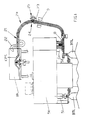
- Figure 1 shows a capping unit for containers, particularly a unit for capping drink bottles of the PET type using screw caps, which unit mainly comprises a hopper 10, a capper 50 and a line 20 supplying capper 50 with caps CPS from hopper 10.
- Hopper 10, of the rotating plate type, and capper 50, which comprises a plurality of capping heads for screwing caps CPS onto bottles BTL, are known in the art and normally used in such systems and accordingly they will not be shown and described in detail.
- Cap supply line 20 is also known and normally used to operate with hopper 10 and capper 50 and the same comprises the already mentioned "trap" device 21.
- This trap 21 is located immediately downstream hopper 10 and causes the caps CPS having the concave portion oriented downwardly to fall into S-shaped pipe 22 wherefrom the same are returned to hopper 10 by a blow of compressed air. It should be said at this point that the caps take the illustrated right position, in which they have the heavier closed or panel portion oriented downwardly, owing to the force of gravity.
- Trap 21 and S-shaped pipe 22 are also well known in the art and they will not be further described and illustrated.
- caps CPS move to capper 50 along supply line 20, the caps having the open concave portion oriented rightwardly in Figure 1 and the closed or panel portion oriented leftwardly.
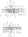
- a star wheel 25, comprising a plurality of arms 26, is mounted on a bracket 23 firmly anchored to length 24 of supply line 20 ( Figures 2 and 3), ends 27 of arms 26 being paddle-shaped.
- Star wheel 25 is mounted on bracket 23 so that, when the same is driven rotating, arms 26 enter window 28 opened in the wall of length 24 of line 20.
- each arm engages the concave portion of each cap CPS as the same pass by window 28 ( Figures 2 and 3) when moving within line 20 in the direction of arrow F1. It is evident that the relationship between each cap CPS and the arm 26 engaging therewith is such that the movement of the caps in the direction of arrow F1 causes idle wheel 25 to rotate in the counterclockwise direction ( Figure 2). Furthermore, a second bracket 29 ( Figures 4 and 5) supporting a light sensor 30 is mounted on length 24 of line 20. Light sensor 30 is of the kind able to emit and receive a ligh beam.
- light sensor 30 emits a light beam RLM directed to hit paddle 27' of arm 26' which follows arm 26" during the rotation of star wheel 25 ( Figures 2, 4 and 5), arm 26" being received within the cap CPS" reaching window 28.
- line 20 is not a pipe having closed walls but comprises four stainless steel guides 20 (A, B, C, D) (see Figure 3B) placed perpendicular to each other and held together by spaced rings 35 to facilitate, when necessary, the access to the train of caps moving therein. Therefore, the openings or windows such as window 28 are formed either by interrupting or by reducing the guide width.
- a double effect pneumatic unit 36 is supported on an appendix 32 of bracket 29, unit 36 being controlled in a known way by solenoid valves (not shown) operated by the electric pulses generated by light sensor 30 whenever beam RLM delivered thereby returns thereto.
- pneumatic unit 36 is such that piston 38 thereof in its active stroke is allowed to fit line 20 through a hole 40 formed in guide 20A and facing an opening 41 formed in guide 20C ( Figure 3) and having such a size that the caps CPS can easily pass therethrough. Opening 41 is closed by a lid 42 hinged on guide 20C to open outwardly when operated, against the bias of a return spring 43.
- the device of the invention works as follows: the train of caps CPS is moved both by gravity and air blows within line 20 from hopper 10 to capper 50, all the caps being oriented as described also owing to the action of trap 21.
- idle star wheel 25 is caused to rotate by the moving caps that push arms 26", the end 27" of which enters the cap CPS" which has passed by window 28 ( Figure 2).
- beam RLM delivered by light sensor 30 hits a side of paddle 27', is reflected within cap CPS where it is reflected three more times and then hits the other face of paddle 27' to be directed outside window 28 (Figure 4).
- light sensor 30 When the reflected beam RLM is received light sensor 30 emits an electric signal that is applied, in a known way, to the solenoid valves of double effect pneumatic unit 36. Accordingly, the piston of unit 36 is pushed into line 20 through hole 40 and violently hits the inverted cap CPS' aligned with hole 40, which cap CPS' causes lid 42 to open against the bias of spring 43 and it is ejected through opening 41.
- cap CPS' is removed in a fraction of a second and accordingly no significant stops in the movement of the caps to the capper take place.
- the double effect pneumatic unit can be replaced by an electromechanical ejector operated by a solenoid controlled by light sensor 30.
Landscapes
- Engineering & Computer Science (AREA)
- Mechanical Engineering (AREA)
- Sealing Of Jars (AREA)
- Closing Of Containers (AREA)
Applications Claiming Priority (2)
| Application Number | Priority Date | Filing Date | Title |
|---|---|---|---|
| ITRM950010 | 1995-01-05 | ||
| IT95RM000010A IT1277135B1 (it) | 1995-01-05 | 1995-01-05 | Dispositivo per l espulsione automatica da un condotto di alimentazione di capsule, tappi o elementi generalmente concavi, di |
Publications (3)
| Publication Number | Publication Date |
|---|---|
| EP0782888A2 true EP0782888A2 (de) | 1997-07-09 |
| EP0782888A3 EP0782888A3 (de) | 1998-03-04 |
| EP0782888B1 EP0782888B1 (de) | 2002-11-13 |
Family
ID=11402908
Family Applications (1)
| Application Number | Title | Priority Date | Filing Date |
|---|---|---|---|
| EP96830002A Expired - Lifetime EP0782888B1 (de) | 1995-01-05 | 1996-01-05 | Vorrichtung zur automatischen Entfernung falsch orientierter Elemente aus einer Zuleitung von Verschlüssen, Steckern oder allgemein konkaven Elementen |
Country Status (3)
| Country | Link |
|---|---|
| EP (1) | EP0782888B1 (de) |
| DE (1) | DE69624779T2 (de) |
| IT (1) | IT1277135B1 (de) |
Cited By (15)
| Publication number | Priority date | Publication date | Assignee | Title |
|---|---|---|---|---|
| WO1999020406A1 (de) * | 1997-10-18 | 1999-04-29 | Krupp Corpoplast Maschinenbau Gmbh | Vorrichtung zur prüfung von vorformlingen |
| EP1357064A1 (de) * | 2002-04-23 | 2003-10-29 | Amcor White Cap Deutschland GmbH & Co. KG | Vertikale Parallelförderung von Deckelverschlüssen |
| US7331443B2 (en) | 2004-04-22 | 2008-02-19 | Amcor Limited | Vertical parallel transportation of caps |
| WO2008022735A1 (de) * | 2006-08-19 | 2008-02-28 | Khs Ag | Vorrichtung zum zuführen von verschlüssen an eine verschliessmaschine |
| WO2008125898A1 (en) * | 2007-04-11 | 2008-10-23 | Sidel Participations | Cap feeding unit having shifted starwheels |
| CN102219114A (zh) * | 2011-05-03 | 2011-10-19 | 广州达意隆包装机械股份有限公司 | 一种剔反盖装置 |
| CN102914546A (zh) * | 2012-10-09 | 2013-02-06 | 昆山广达科技设备有限公司 | 一种基于机器视觉的喷雾罐罐盖质量检测系统和方法 |
| CN103086145A (zh) * | 2013-01-16 | 2013-05-08 | 南京保立隆包装机械有限公司 | 一种检盖装置 |
| CN103130158A (zh) * | 2013-03-06 | 2013-06-05 | 长沙经济技术开发区博雅机械有限公司 | 塑料瓶盖压盖机 |
| CN105000362A (zh) * | 2015-08-10 | 2015-10-28 | 江苏艾萨克科技有限公司 | 一种自动理管机 |
| EP2789574B1 (de) | 2013-01-11 | 2017-06-28 | Krones AG | Aseptikfüller sowie Verfahren zur Behandlung von Behälterverschlüssen in einem Aseptikfüller |
| CN108082906A (zh) * | 2017-12-29 | 2018-05-29 | 茂名市腾龙工业皮带有限公司 | 一种棘轮机构 |
| DE10307601B4 (de) | 2002-04-23 | 2019-07-04 | Silgan Holdings Inc.(N.D.Ges.D.Staates Delaware) | Verfahren und Vorrichtung zum Fördern von Verschlüssen aus Metallblech |
| CN114348666A (zh) * | 2022-01-05 | 2022-04-15 | 广州达意隆包装机械股份有限公司 | 反盖剔除装置 |
| CN116002599A (zh) * | 2021-10-21 | 2023-04-25 | 克朗斯公司 | 用于在饮料灌装设备中将封闭件供应给封闭器的装置 |
Families Citing this family (3)
| Publication number | Priority date | Publication date | Assignee | Title |
|---|---|---|---|---|
| DE102011016858B4 (de) * | 2011-04-13 | 2026-03-26 | Krones Aktiengesellschaft | Vorrichtung und Verfahren zum Transportieren von Kunststoffvorformlingen |
| DE102020123392A1 (de) | 2020-09-08 | 2022-03-10 | Khs Gmbh | Vorrichtung und Verfahren zum Fördern von Behälterverschlüssen |
| DE102023100794A1 (de) * | 2023-01-13 | 2024-07-18 | Bausch + Ströbel SE + Co. KG | Transporteinrichtung zum Transport von insbesondere pharmazeutischen Behältern und Vorrichtung zum Verarbeiten solcher Behälter |
Family Cites Families (2)
| Publication number | Priority date | Publication date | Assignee | Title |
|---|---|---|---|---|
| US4895243A (en) * | 1988-05-26 | 1990-01-23 | Graham S Neal | Starwheel cap selecting apparatus |
| NL8901626A (nl) * | 1989-06-27 | 1991-01-16 | Thomassen & Drijver | Inrichting voor het uitstoten van verkeerd geoerienteerde deksels uit een continue stroom. |
-
1995
- 1995-01-05 IT IT95RM000010A patent/IT1277135B1/it active IP Right Grant
-
1996
- 1996-01-05 DE DE69624779T patent/DE69624779T2/de not_active Expired - Lifetime
- 1996-01-05 EP EP96830002A patent/EP0782888B1/de not_active Expired - Lifetime
Cited By (22)
| Publication number | Priority date | Publication date | Assignee | Title |
|---|---|---|---|---|
| WO1999020406A1 (de) * | 1997-10-18 | 1999-04-29 | Krupp Corpoplast Maschinenbau Gmbh | Vorrichtung zur prüfung von vorformlingen |
| EP1357064A1 (de) * | 2002-04-23 | 2003-10-29 | Amcor White Cap Deutschland GmbH & Co. KG | Vertikale Parallelförderung von Deckelverschlüssen |
| DE10307601B4 (de) | 2002-04-23 | 2019-07-04 | Silgan Holdings Inc.(N.D.Ges.D.Staates Delaware) | Verfahren und Vorrichtung zum Fördern von Verschlüssen aus Metallblech |
| US7837022B2 (en) | 2004-04-22 | 2010-11-23 | Silgan Holdings, Inc. | Vertical parallel transportation of caps |
| US7331443B2 (en) | 2004-04-22 | 2008-02-19 | Amcor Limited | Vertical parallel transportation of caps |
| WO2008022735A1 (de) * | 2006-08-19 | 2008-02-28 | Khs Ag | Vorrichtung zum zuführen von verschlüssen an eine verschliessmaschine |
| JP2010501436A (ja) * | 2006-08-19 | 2010-01-21 | カーハーエス・アクチエンゲゼルシヤフト | 蓋を蓋付け機に供給する装置 |
| RU2416562C2 (ru) * | 2006-08-19 | 2011-04-20 | Кхс Аг | Устройство для подачи крышек к укупорочной машине |
| CN101516747B (zh) * | 2006-08-19 | 2013-12-18 | Khs有限责任公司 | 用于将封盖供给到封口机的装置 |
| US10207835B2 (en) | 2006-08-19 | 2019-02-19 | Khs Gmbh | Capping machine in a beverage bottling plant configures to cap beverage bottles with beverage bottle crown caps or beverage bottle screw caps and a capping machine configured to cap containers with container caps |
| WO2008125898A1 (en) * | 2007-04-11 | 2008-10-23 | Sidel Participations | Cap feeding unit having shifted starwheels |
| CN101678965B (zh) * | 2007-04-11 | 2014-08-13 | 西德尔合作公司 | 具有偏移星形轮的盖供给单元 |
| CN102219114A (zh) * | 2011-05-03 | 2011-10-19 | 广州达意隆包装机械股份有限公司 | 一种剔反盖装置 |
| CN102914546A (zh) * | 2012-10-09 | 2013-02-06 | 昆山广达科技设备有限公司 | 一种基于机器视觉的喷雾罐罐盖质量检测系统和方法 |
| EP2789574B1 (de) | 2013-01-11 | 2017-06-28 | Krones AG | Aseptikfüller sowie Verfahren zur Behandlung von Behälterverschlüssen in einem Aseptikfüller |
| CN103086145A (zh) * | 2013-01-16 | 2013-05-08 | 南京保立隆包装机械有限公司 | 一种检盖装置 |
| CN103130158B (zh) * | 2013-03-06 | 2015-04-01 | 长沙经济技术开发区博雅机械有限公司 | 塑料瓶盖压盖机 |
| CN103130158A (zh) * | 2013-03-06 | 2013-06-05 | 长沙经济技术开发区博雅机械有限公司 | 塑料瓶盖压盖机 |
| CN105000362A (zh) * | 2015-08-10 | 2015-10-28 | 江苏艾萨克科技有限公司 | 一种自动理管机 |
| CN108082906A (zh) * | 2017-12-29 | 2018-05-29 | 茂名市腾龙工业皮带有限公司 | 一种棘轮机构 |
| CN116002599A (zh) * | 2021-10-21 | 2023-04-25 | 克朗斯公司 | 用于在饮料灌装设备中将封闭件供应给封闭器的装置 |
| CN114348666A (zh) * | 2022-01-05 | 2022-04-15 | 广州达意隆包装机械股份有限公司 | 反盖剔除装置 |
Also Published As
| Publication number | Publication date |
|---|---|
| ITRM950010A0 (it) | 1995-01-05 |
| IT1277135B1 (it) | 1997-11-04 |
| EP0782888B1 (de) | 2002-11-13 |
| EP0782888A3 (de) | 1998-03-04 |
| DE69624779D1 (de) | 2002-12-19 |
| DE69624779T2 (de) | 2003-07-17 |
| ITRM950010A1 (it) | 1996-07-05 |
Similar Documents
| Publication | Publication Date | Title |
|---|---|---|
| EP0782888B1 (de) | Vorrichtung zur automatischen Entfernung falsch orientierter Elemente aus einer Zuleitung von Verschlüssen, Steckern oder allgemein konkaven Elementen | |
| US6520318B1 (en) | Device for introducing and/or eliminating containers | |
| US20100037557A1 (en) | Capping machine in a beverage bottling plant configured to cap beverage bottles with beverage bottle crown caps or beverage bottle screw caps and a capping machine configured to cap containers with container caps | |
| US6390328B1 (en) | Modular article dispensing unit for an automatic vending machine | |
| US8704674B2 (en) | Device for detecting wrong position of a container in a container handling machine | |
| WO1991006496A1 (en) | Pellet dispenser | |
| EP2196417B1 (de) | Vorrichtung zum orientieren von Gegenständen, insbesondere von Verschlusskappen | |
| JPH01288514A (ja) | 形成品引渡し装置 | |
| CA2451567A1 (en) | Container diverter | |
| US6961638B2 (en) | Reject bottle detection and ejection mechanisms | |
| JPS587557B2 (ja) | 回転式構造の容器蓋閉じ機械のコルク送りロツク機構の制御装置 | |
| US11795010B2 (en) | Transport device and method for transporting containers in a manner revolving about a vertical machine axis | |
| US4337608A (en) | Method and apparatus for cleaning bottle filling devices after bottle breakage | |
| JPH0470069B2 (de) | ||
| US20050061619A1 (en) | Foreign bottle detection device | |
| US5464089A (en) | Electromagnet crown sorting and un-jamming device | |
| WO1995007770A1 (en) | Device for sorting and distributing of packaging units | |
| US3722658A (en) | Closure handling and orienting apparatus | |
| JPH05310319A (ja) | 高速搬送ライン上におけるワーク休止装置 | |
| US3421616A (en) | Ejector apparatus for article feedlines | |
| US5309694A (en) | Device for use with a closure magazine for introducing closures into a closure channel | |
| JPH01242310A (ja) | 容器整列ミス品のライン外自動排出システム | |
| SU654498A1 (ru) | Устройство дл подачи круглой тары | |
| CN222592525U (zh) | 一种自动分离装置 | |
| SU212643A1 (ru) | УСТРОЙСТВО дл ХРАНЕНИЯ И ВЫДАЧИ ШТУЧНЫХ ТОВАРОВ |
Legal Events
| Date | Code | Title | Description |
|---|---|---|---|
| PUAI | Public reference made under article 153(3) epc to a published international application that has entered the european phase |
Free format text: ORIGINAL CODE: 0009012 |
|
| AK | Designated contracting states |
Kind code of ref document: A2 Designated state(s): DE ES FR GB |
|
| PUAL | Search report despatched |
Free format text: ORIGINAL CODE: 0009013 |
|
| AK | Designated contracting states |
Kind code of ref document: A3 Designated state(s): DE ES FR GB |
|
| 17P | Request for examination filed |
Effective date: 19980903 |
|
| 17Q | First examination report despatched |
Effective date: 20001023 |
|
| GRAG | Despatch of communication of intention to grant |
Free format text: ORIGINAL CODE: EPIDOS AGRA |
|
| GRAG | Despatch of communication of intention to grant |
Free format text: ORIGINAL CODE: EPIDOS AGRA |
|
| GRAH | Despatch of communication of intention to grant a patent |
Free format text: ORIGINAL CODE: EPIDOS IGRA |
|
| GRAH | Despatch of communication of intention to grant a patent |
Free format text: ORIGINAL CODE: EPIDOS IGRA |
|
| GRAH | Despatch of communication of intention to grant a patent |
Free format text: ORIGINAL CODE: EPIDOS IGRA |
|
| GRAA | (expected) grant |
Free format text: ORIGINAL CODE: 0009210 |
|
| AK | Designated contracting states |
Kind code of ref document: B1 Designated state(s): DE ES FR GB |
|
| REG | Reference to a national code |
Ref country code: GB Ref legal event code: FG4D |
|
| REF | Corresponds to: |
Ref document number: 69624779 Country of ref document: DE Date of ref document: 20021219 |
|
| PG25 | Lapsed in a contracting state [announced via postgrant information from national office to epo] |
Ref country code: GB Free format text: LAPSE BECAUSE OF NON-PAYMENT OF DUE FEES Effective date: 20030213 |
|
| PG25 | Lapsed in a contracting state [announced via postgrant information from national office to epo] |
Ref country code: ES Free format text: LAPSE BECAUSE OF FAILURE TO SUBMIT A TRANSLATION OF THE DESCRIPTION OR TO PAY THE FEE WITHIN THE PRESCRIBED TIME-LIMIT Effective date: 20030529 |
|
| ET | Fr: translation filed | ||
| PLBE | No opposition filed within time limit |
Free format text: ORIGINAL CODE: 0009261 |
|
| STAA | Information on the status of an ep patent application or granted ep patent |
Free format text: STATUS: NO OPPOSITION FILED WITHIN TIME LIMIT |
|
| GBPC | Gb: european patent ceased through non-payment of renewal fee | ||
| 26N | No opposition filed |
Effective date: 20030814 |
|
| PGFP | Annual fee paid to national office [announced via postgrant information from national office to epo] |
Ref country code: FR Payment date: 20111226 Year of fee payment: 17 |
|
| PGFP | Annual fee paid to national office [announced via postgrant information from national office to epo] |
Ref country code: DE Payment date: 20111216 Year of fee payment: 17 |
|
| REG | Reference to a national code |
Ref country code: FR Ref legal event code: ST Effective date: 20130930 |
|
| PG25 | Lapsed in a contracting state [announced via postgrant information from national office to epo] |
Ref country code: DE Free format text: LAPSE BECAUSE OF NON-PAYMENT OF DUE FEES Effective date: 20130801 |
|
| REG | Reference to a national code |
Ref country code: DE Ref legal event code: R119 Ref document number: 69624779 Country of ref document: DE Effective date: 20130801 |
|
| PG25 | Lapsed in a contracting state [announced via postgrant information from national office to epo] |
Ref country code: FR Free format text: LAPSE BECAUSE OF NON-PAYMENT OF DUE FEES Effective date: 20130131 |