EP0782936A1 - Bandage pneumatique - Google Patents
Bandage pneumatique Download PDFInfo
- Publication number
- EP0782936A1 EP0782936A1 EP96309413A EP96309413A EP0782936A1 EP 0782936 A1 EP0782936 A1 EP 0782936A1 EP 96309413 A EP96309413 A EP 96309413A EP 96309413 A EP96309413 A EP 96309413A EP 0782936 A1 EP0782936 A1 EP 0782936A1
- Authority
- EP
- European Patent Office
- Prior art keywords
- circumferential
- width
- groove
- tyre
- ground contacting
- Prior art date
- Legal status (The legal status is an assumption and is not a legal conclusion. Google has not performed a legal analysis and makes no representation as to the accuracy of the status listed.)
- Granted
Links
- 230000004323 axial length Effects 0.000 claims description 2
- 238000012360 testing method Methods 0.000 description 21
- 239000011324 bead Substances 0.000 description 5
- XLYOFNOQVPJJNP-UHFFFAOYSA-N water Substances O XLYOFNOQVPJJNP-UHFFFAOYSA-N 0.000 description 5
- 230000007423 decrease Effects 0.000 description 3
- 230000003247 decreasing effect Effects 0.000 description 3
- 230000001133 acceleration Effects 0.000 description 2
- 238000011056 performance test Methods 0.000 description 2
- 230000008094 contradictory effect Effects 0.000 description 1
- 230000000694 effects Effects 0.000 description 1
- 230000007613 environmental effect Effects 0.000 description 1
- 230000007246 mechanism Effects 0.000 description 1
- 238000012986 modification Methods 0.000 description 1
- 230000004048 modification Effects 0.000 description 1
- 238000013112 stability test Methods 0.000 description 1
- 238000010998 test method Methods 0.000 description 1
Images



Classifications
-
- B—PERFORMING OPERATIONS; TRANSPORTING
- B60—VEHICLES IN GENERAL
- B60C—VEHICLE TYRES; TYRE INFLATION; TYRE CHANGING; CONNECTING VALVES TO INFLATABLE ELASTIC BODIES IN GENERAL; DEVICES OR ARRANGEMENTS RELATED TO TYRES
- B60C11/00—Tyre tread bands; Tread patterns; Anti-skid inserts
- B60C11/03—Tread patterns
- B60C11/0306—Patterns comprising block rows or discontinuous ribs
-
- B—PERFORMING OPERATIONS; TRANSPORTING
- B60—VEHICLES IN GENERAL
- B60C—VEHICLE TYRES; TYRE INFLATION; TYRE CHANGING; CONNECTING VALVES TO INFLATABLE ELASTIC BODIES IN GENERAL; DEVICES OR ARRANGEMENTS RELATED TO TYRES
- B60C11/00—Tyre tread bands; Tread patterns; Anti-skid inserts
- B60C11/03—Tread patterns
- B60C11/0302—Tread patterns directional pattern, i.e. with main rolling direction
-
- B—PERFORMING OPERATIONS; TRANSPORTING
- B60—VEHICLES IN GENERAL
- B60C—VEHICLE TYRES; TYRE INFLATION; TYRE CHANGING; CONNECTING VALVES TO INFLATABLE ELASTIC BODIES IN GENERAL; DEVICES OR ARRANGEMENTS RELATED TO TYRES
- B60C11/00—Tyre tread bands; Tread patterns; Anti-skid inserts
- B60C11/03—Tread patterns
- B60C11/0318—Tread patterns irregular patterns with particular pitch sequence
-
- B—PERFORMING OPERATIONS; TRANSPORTING
- B60—VEHICLES IN GENERAL
- B60C—VEHICLE TYRES; TYRE INFLATION; TYRE CHANGING; CONNECTING VALVES TO INFLATABLE ELASTIC BODIES IN GENERAL; DEVICES OR ARRANGEMENTS RELATED TO TYRES
- B60C11/00—Tyre tread bands; Tread patterns; Anti-skid inserts
- B60C11/03—Tread patterns
- B60C11/12—Tread patterns characterised by the use of narrow slits or incisions, e.g. sipes
-
- B—PERFORMING OPERATIONS; TRANSPORTING
- B60—VEHICLES IN GENERAL
- B60C—VEHICLE TYRES; TYRE INFLATION; TYRE CHANGING; CONNECTING VALVES TO INFLATABLE ELASTIC BODIES IN GENERAL; DEVICES OR ARRANGEMENTS RELATED TO TYRES
- B60C11/00—Tyre tread bands; Tread patterns; Anti-skid inserts
- B60C11/03—Tread patterns
- B60C2011/0337—Tread patterns characterised by particular design features of the pattern
- B60C2011/0339—Grooves
- B60C2011/0374—Slant grooves, i.e. having an angle of about 5 to 35 degrees to the equatorial plane
Definitions
- the present invention relates to a pneumatic tyre with an improved tread region capable of reducing pass-by noise and improving wet performances.
- the air tube resonance sound can be reduced by decreasing the width of a circumferential groove and/or the number of circumferential grooves in the tread.
- an object of the present invention to provide to a pneumatic tyre in which the above-mentioned contradictory problems can be solved, that is, pass-by noise is reduced and drainage is improved.
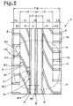
- a pneumatic tyre comprises a tread portion having a ground contacting width TW, provided in a central region Y1 with a wide circumferential groove having a groove width W1 of from 0.05 to 0.15 times the ground contacting width TW and extending continuously in the tyre circumferential direction, where the central region Y1 is defined as being between a pair of first circumferential lines X1 one drawn on each side of the tyre equator at an axial distance L1 from the tyre equator of 0.1 to 0.15 times the ground contacting width TW, wherein the tread portion is not provided either in the middle regions Y2 or in the shoulder regions Y3 with a circumferential continuously extending groove, but a plurality of axial grooves each extending from the central region Y1 through one of the middle regions Y2 and one of the shoulder regions Y3 to one of tread edges, the axial grooves having a groove width W2 of from 0.02 to 0.0
- the middle regions Y2 are provided with sipes having a width of not more than 1.5 mm, wherein, in each region which is surround by the circumferentially adjacent axial grooves G and the first and second circumferential lines X1 and X2, the total LC of the circumferential components of all the sipes therein, the total LW of the axial components thereof, and the ground contacting width TW satisfy: 0.7 ⁇ (LC+LW)/TW ⁇ 1.2.
- the tyre 1 comprises, as shown in Fig.1, a tread portion 2, a pair of sidewall portions 3, a pair of bead portions 4 each with a bead core 5 therein, a radial carcass 6 extending between the bead portions 4 and turned up around the bead cores 5 to be secured in the bead portions 4, and a belt 7 disposed radially outside the carcass 6 and inside the tread 2.
- a central region Y1 of the tread portion 2 is provided with at least one wide circumferential groove M extending continuously in the tyre circumferential direction.
- a pair of middle regions Y2 and a pair of shoulder regions Y3 of the tread portion 2 are not provided with any circumferentially continuously extending groove, but a plurality of axial grooves G.
- the central region Y1 is defined between a pair of first circumferential lines X1 each drawn on each side of the tyre equator C at an axial distance L1 from the tyre equator C.
- the distance L1 is 0.125, times the ground contacting width TW of the tread portion 2.
- Each of the middle regions Y2 is defined between one of the first circumferential lines X1 and a second circumferential line X2 drawn at an axial distance L2 from the tyre equator C.
- the distance L2 is 0.35 times the ground contacting width TW.
- Each of the shoulder regions Y3 is defined as extending axially outwardly from the second circumferential line X2.
- the ground contacting width TW is defined as the maximum ground contacting width between the axial outermost edges of the ground contacting area Y when the tyre is mounted on its standard rim, inflated to its standard pressure (2.0kgf/sq.cm in this example), and then loaded with 70 % of the maximum load.
- standard rim a rim officially approved for the tyre by, for example JATMA (Japan), TRA (USA), ETRTO (Europe) and the like is used.
- the standard pressure and the maximum load are those specified by the same associations.
- the wide circumferential groove M is centred on the tyre equator C, and the groove width W1 thereof is set in the range of from 0.05 to 0.15 times the ground contacting width TW.
- the wide circumferential groove M is independent, namely, no groove is connected thereto, and in this example it is a straight groove. Therefore, a big water drainage towards the front and rear directions is provided in the central region Y1.
- the resonance sound hardly leaks outside the tyre because no groove is connected to the wide groove.
- the central region Y1 is further provided on each side of the wide circumferential groove M with a narrow circumferential groove m extending continuously in the tyre circumferential direction.
- the narrow circumferential groove m is a straight groove, and the groove width W3 thereof is less than 0.05 times, in this example 0.02 to 0.035 times the ground contacting width TW.
- the drainage from the central region Y1 is further improved without increasing the air tube resonance sound because an air tube resonance phenomenon hardly occurs in such a narrow groove.
- the circumferential grooves M and m are preferably straight, but a gentle zigzag or wavy configuration may be used.
- the axial grooves G extend across the whole width of the middle region Y2 and shoulder region Y3, and the inner end Gi of each axial groove G is connected to one of the narrow circumferential grooves m, and the outer end Go thereof is open to the tread edge E.
- the axial grooves G have a relatively narrow groove width W2 of from 0.02 to 0.035 times the ground contacting width TW to preclude air resonance noise being generated.
- the inner ends Gi are preferably terminated in the central region Y1 without connecting to the central wide circumferential groove M.
- the main part G1 of the axial groove G which is defined as a part in the middle region Y2 intersect or cross the first circumferential line X1 at an angle ⁇ 1 of from 10 to 25 degrees and intersect the second circumferential line X2 at an angle ⁇ 2 of from 30 to 45 degrees.
- the main part G1 is bent in the middle thereof so as to be composed of two straight segments.
- the outer part G2 of the axial groove G which is defined as the part in the shoulder region Y3 is inclined at an angle 3 of from 90 to 60 degrees, in this example 90 degrees with respect to the tyre circumferential direction. Accordingly, the axial groove G is bent at the line X2, forming an angle of 60 to 45 degrees.
- the number of axial grooves G which is equal to the number of all the existing grooves (exclude sipes) is preferably set in the range of from 25 to 45 in case of passenger car tyres. If the number is less than 25, the improvement in wet performance is insufficient. If the number is more than 45, running noise increases.
- a lug groove 10 is disposed between the axial grooves G, which lug groove 10 is substantially the same as the outer part G2 in respect of the width and inclination angle. Therefore, the number of all the existing grooves (exclude sipes) is doubled.
- the axial grooves G are inclined in the same direction.
- the inclining direction on one side is the same as the other side.
- the inclining direction on one side can be reversed to the other side as shown in Fig.4.
- the tread pattern shown in Fig.4 is otherwise the same as the pattern shown in Fig.2.
- the groove width W1 is more than 0.15 TW, the resonance noise is liable to leak. If the groove width W1 is less than 0.05 TW, the wet performances are greatly decreased.
- the groove width W2 is more than 0.035 TW, the noise is liable to increase. If the groove width W2 is less than 0.02 TW, the wet performances are greatly decreased.
- the inclination angle of the axial grooves G to the circumferential direction is relatively small in the axially inner part. Therefore, in and near the central region Y1, the axial grooves G function as a circumferential groove to improve drainage in this region.
- the inclination angle is larger in the axially outer part. Therefore, the groove line is akin to the actual flow line of the water discharged sideways from the tread centre, and the resistance to water flow is thus lower.
- middle and shoulder regions Y2 and Y3 are not provided with a circumferential groove, and the axial grooves G have a narrow width and an inclination angle. Accordingly, the occurrence of air tube resonance is effectively prevented and then the pass-by noise is minimised.
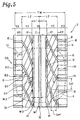
- Figs.5 and 6 show modifications of the tread patterns shown in Figs.2 and 4, respectively, wherein sipes 11 are disposed in the middle regions Y2 and optionally in the shoulder regions Y3.
- a sipe is a cut or slit having a width of not more than 1.5 mm and less than the width W3 of the narrow circumferential grooves m.
- Each sipe 11 has two ends which are not terminated in the tread rubber but open to the above-mentioned grooves such as the circumferential grooves M and m, the axial grooves G and the lug grooves 10.
- the arrangement is such that the total length LC of the circumferential lengths Lci of all the sipes 11 therein, the total length LW of the axial lengths Lwi thereof, and the above-mentioned ground contacting width TW satisfy the following relationship: 0.7 ⁇ (LC+LW)/TW ⁇ 1.2.
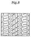
- the sipes 11 in Figs. 5 and 6 are straight in the middle regions Y2, but it is possible to bend the sipes as shown in Fig.7.
- the test car was coasted for a 50 meter distance at 60 km/h and 35 km/h on a straight test course, and the maximum noise sound level was measured with a microphone set at 1.2 meter height from the road surface and 7.5 meter sideways from the course.
- test car was run on various road surfaces on a test course, and the performances were evaluated by the test driver's feelings. The results are indicated by an index based on that the tyre No.9 is 100. The larger the index, the better the performance.
- the test results and tyre specifications are shown in the following Table 1. Through the tests, it was confirmed that the tyres according to the present invention were improved in both aquaplaning performance and pass-by noise.
Landscapes
- Engineering & Computer Science (AREA)
- Mechanical Engineering (AREA)
- Tires In General (AREA)
Applications Claiming Priority (3)
| Application Number | Priority Date | Filing Date | Title |
|---|---|---|---|
| JP35309495 | 1995-12-29 | ||
| JP35309495 | 1995-12-29 | ||
| JP353094/95 | 1995-12-29 |
Publications (2)
| Publication Number | Publication Date |
|---|---|
| EP0782936A1 true EP0782936A1 (fr) | 1997-07-09 |
| EP0782936B1 EP0782936B1 (fr) | 2001-07-18 |
Family
ID=18428527
Family Applications (1)
| Application Number | Title | Priority Date | Filing Date |
|---|---|---|---|
| EP96309413A Expired - Lifetime EP0782936B1 (fr) | 1995-12-29 | 1996-12-23 | Bandage pneumatique |
Country Status (3)
| Country | Link |
|---|---|
| US (1) | US5837074A (fr) |
| EP (1) | EP0782936B1 (fr) |
| DE (1) | DE69613952T2 (fr) |
Cited By (5)
| Publication number | Priority date | Publication date | Assignee | Title |
|---|---|---|---|---|
| EP0816130A1 (fr) * | 1996-06-28 | 1998-01-07 | Sumitomo Rubber Industries Limited | Bandage pneumatique |
| EP1120295A3 (fr) * | 2000-01-24 | 2003-02-12 | Sumitomo Rubber Industries Ltd. | Bandage pneumatique |
| EP1495882A1 (fr) * | 2003-07-07 | 2005-01-12 | The Goodyear Tire & Rubber Company | Perfectionnement dans le bruit de roulement par modulation de la fréquence de résonnance de la rainure |
| CN102310724A (zh) * | 2010-06-18 | 2012-01-11 | 横滨橡胶株式会社 | 充气轮胎 |
| US10245889B2 (en) | 2012-11-30 | 2019-04-02 | Bridgestone Corporation | Pneumatic tire having lug grooves forming a direction tread pattern |
Families Citing this family (12)
| Publication number | Priority date | Publication date | Assignee | Title |
|---|---|---|---|---|
| JP3718021B2 (ja) * | 1997-02-21 | 2005-11-16 | 株式会社ブリヂストン | オール・シーズン乗用車用空気入りラジアル・タイヤ |
| JP3391755B2 (ja) * | 1999-12-06 | 2003-03-31 | 住友ゴム工業株式会社 | 空気入りタイヤ |
| USD450032S1 (en) | 2000-06-13 | 2001-11-06 | The Goodyear Tire & Rubber Company | Tire tread |
| JP2006347227A (ja) * | 2005-06-13 | 2006-12-28 | Toyo Tire & Rubber Co Ltd | 空気入りタイヤ |
| JP4764085B2 (ja) * | 2005-07-22 | 2011-08-31 | 株式会社ブリヂストン | 空気入りタイヤ |
| US7594703B2 (en) * | 2007-05-14 | 2009-09-29 | Hall David R | Pick with a reentrant |
| JP5294735B2 (ja) * | 2008-07-03 | 2013-09-18 | 株式会社ブリヂストン | 空気入りタイヤ |
| DE102010016469A1 (de) * | 2010-04-16 | 2011-10-20 | Continental Reifen Deutschland Gmbh | Fahrzeugluftreifen für Nutzfahrzeuge |
| JP6306436B2 (ja) * | 2014-05-30 | 2018-04-04 | 株式会社ブリヂストン | 空気入りタイヤ |
| JP6312783B1 (ja) * | 2016-12-09 | 2018-04-18 | 東洋ゴム工業株式会社 | 空気入りタイヤ |
| US20230062051A1 (en) * | 2019-12-31 | 2023-03-02 | Sadi Kose | Tire having corkscrew sculpture with inverted central rib features |
| JP7694270B2 (ja) * | 2021-09-02 | 2025-06-18 | 住友ゴム工業株式会社 | タイヤ |
Citations (4)
| Publication number | Priority date | Publication date | Assignee | Title |
|---|---|---|---|---|
| DE3707953A1 (de) * | 1986-03-14 | 1987-10-15 | Bridgestone Corp | Radialreifen fuer hochgeschwindigkeitsfahrzeuge |
| EP0488740A1 (fr) * | 1990-11-30 | 1992-06-03 | Bridgestone Corporation | Bandages pneumatiques |
| EP0588781A1 (fr) * | 1992-09-15 | 1994-03-23 | Semperit Reifen Aktiengesellschaft | Bandage pneumatique pour véhicule |
| EP0627332A1 (fr) * | 1993-05-31 | 1994-12-07 | PIRELLI COORDINAMENTO PNEUMATICI S.p.A. | Bandage pneumatique pour roues de véhicule motorisé pourvu d'une bande de roulement peu bruyante |
Family Cites Families (9)
| Publication number | Priority date | Publication date | Assignee | Title |
|---|---|---|---|---|
| DE614574C (de) * | 1933-06-09 | 1935-06-13 | Gottfried Kiewitt | Elastischer Radreifen fuer Kraftfahrzeuge, Fahrraeder und andere Fahrzeuge |
| DE2455130A1 (de) * | 1974-11-21 | 1976-05-26 | Continental Gummi Werke Ag | Luftreifen fuer kraftfahrzeuge |
| US4700762A (en) * | 1985-03-22 | 1987-10-20 | The Goodyear Tire & Rubber Company | Pneumatic tire therad with wide central groove and arcuate grooves |
| DE9000204U1 (de) * | 1990-01-10 | 1991-02-21 | Uniroyal Englebert Reifen GmbH, 5100 Aachen | Fahrzeugluftreifen |
| DE9000203U1 (de) * | 1990-01-10 | 1991-02-21 | Uniroyal Englebert Reifen GmbH, 5100 Aachen | Fahrzeugluftreifen |
| DE9002986U1 (de) * | 1990-03-12 | 1991-04-04 | Uniroyal Englebert Reifen GmbH, 5100 Aachen | Fahrzeugluftreifen |
| US5176766B1 (en) * | 1991-03-08 | 1996-04-30 | Goodyear Tire & Rubber | Pneumatic tire having a unique footprint |
| FR2692201A1 (fr) * | 1992-06-11 | 1993-12-17 | Michelin & Cie | Train de pneumatiques à sculptures directionnelles. |
| US5501258A (en) * | 1994-06-27 | 1996-03-26 | Pirelli Armstrong Tire Corporation | Tire tread having a circumferential groove deeper than tread element height |
-
1996
- 1996-12-23 US US08/771,923 patent/US5837074A/en not_active Expired - Fee Related
- 1996-12-23 EP EP96309413A patent/EP0782936B1/fr not_active Expired - Lifetime
- 1996-12-23 DE DE69613952T patent/DE69613952T2/de not_active Expired - Fee Related
Patent Citations (4)
| Publication number | Priority date | Publication date | Assignee | Title |
|---|---|---|---|---|
| DE3707953A1 (de) * | 1986-03-14 | 1987-10-15 | Bridgestone Corp | Radialreifen fuer hochgeschwindigkeitsfahrzeuge |
| EP0488740A1 (fr) * | 1990-11-30 | 1992-06-03 | Bridgestone Corporation | Bandages pneumatiques |
| EP0588781A1 (fr) * | 1992-09-15 | 1994-03-23 | Semperit Reifen Aktiengesellschaft | Bandage pneumatique pour véhicule |
| EP0627332A1 (fr) * | 1993-05-31 | 1994-12-07 | PIRELLI COORDINAMENTO PNEUMATICI S.p.A. | Bandage pneumatique pour roues de véhicule motorisé pourvu d'une bande de roulement peu bruyante |
Cited By (10)
| Publication number | Priority date | Publication date | Assignee | Title |
|---|---|---|---|---|
| EP0816130A1 (fr) * | 1996-06-28 | 1998-01-07 | Sumitomo Rubber Industries Limited | Bandage pneumatique |
| US6343636B1 (en) | 1996-06-28 | 2002-02-05 | Sumitomo Rubber Industries, Ltd. | Pneumatic tire including non-directional tread pattern |
| EP1120295A3 (fr) * | 2000-01-24 | 2003-02-12 | Sumitomo Rubber Industries Ltd. | Bandage pneumatique |
| US6626215B2 (en) | 2000-01-24 | 2003-09-30 | Sumitomo Rubber Industries, Ltd. | Pneumatic tire including long and narrow blocks with at least two sipes |
| KR100791867B1 (ko) * | 2000-01-24 | 2008-01-07 | 스미도모 고무 고교 가부시기가이샤 | 공기 타이어 |
| CN100436165C (zh) * | 2000-01-24 | 2008-11-26 | 住友橡胶工业株式会社 | 充气轮胎 |
| EP1495882A1 (fr) * | 2003-07-07 | 2005-01-12 | The Goodyear Tire & Rubber Company | Perfectionnement dans le bruit de roulement par modulation de la fréquence de résonnance de la rainure |
| CN102310724A (zh) * | 2010-06-18 | 2012-01-11 | 横滨橡胶株式会社 | 充气轮胎 |
| US10245889B2 (en) | 2012-11-30 | 2019-04-02 | Bridgestone Corporation | Pneumatic tire having lug grooves forming a direction tread pattern |
| EP2927025B1 (fr) * | 2012-11-30 | 2021-03-17 | Bridgestone Corporation | Pneumatique |
Also Published As
| Publication number | Publication date |
|---|---|
| US5837074A (en) | 1998-11-17 |
| DE69613952T2 (de) | 2001-11-08 |
| EP0782936B1 (fr) | 2001-07-18 |
| DE69613952D1 (de) | 2001-08-23 |
Similar Documents
| Publication | Publication Date | Title |
|---|---|---|
| EP3705314B1 (fr) | Pneumatique | |
| US6340040B1 (en) | Vehicle tire including main grooves and lug grooves | |
| EP0594380B1 (fr) | Bandage pneumatique | |
| US9950572B2 (en) | Pneumatic tire | |
| EP2716477B1 (fr) | Pneu | |
| EP0648622B1 (fr) | Bandage pneumatique | |
| EP0787599B1 (fr) | Bandage pneumatique | |
| EP0782936B1 (fr) | Bandage pneumatique | |
| US11560018B2 (en) | Tyre | |
| EP0858916A2 (fr) | Bandage pneumatique pour véhicule | |
| EP0728599B1 (fr) | Bandage pneumatique | |
| EP0661182B1 (fr) | Bandage pneumatique | |
| JP3332358B2 (ja) | 空気入りタイヤ | |
| EP0676305B1 (fr) | Bandage pneumatique | |
| JP2698739B2 (ja) | 空気入りタイヤ | |
| JPH07186628A (ja) | 空気入りタイヤ | |
| CN114829163B (zh) | 轮胎 | |
| EP0678403B1 (fr) | Bandage pneumatique | |
| US11780270B2 (en) | Tire | |
| JPH06191226A (ja) | 空気入りタイヤ | |
| EP0791487B1 (fr) | Bandage pneumatique | |
| JP3046818B1 (ja) | 空気入りタイヤ | |
| JP2742363B2 (ja) | 空気入りタイヤ |
Legal Events
| Date | Code | Title | Description |
|---|---|---|---|
| PUAI | Public reference made under article 153(3) epc to a published international application that has entered the european phase |
Free format text: ORIGINAL CODE: 0009012 |
|
| AK | Designated contracting states |
Kind code of ref document: A1 Designated state(s): DE FR GB |
|
| 17P | Request for examination filed |
Effective date: 19971125 |
|
| 17Q | First examination report despatched |
Effective date: 19991104 |
|
| GRAG | Despatch of communication of intention to grant |
Free format text: ORIGINAL CODE: EPIDOS AGRA |
|
| GRAG | Despatch of communication of intention to grant |
Free format text: ORIGINAL CODE: EPIDOS AGRA |
|
| GRAH | Despatch of communication of intention to grant a patent |
Free format text: ORIGINAL CODE: EPIDOS IGRA |
|
| GRAH | Despatch of communication of intention to grant a patent |
Free format text: ORIGINAL CODE: EPIDOS IGRA |
|
| GRAA | (expected) grant |
Free format text: ORIGINAL CODE: 0009210 |
|
| AK | Designated contracting states |
Kind code of ref document: B1 Designated state(s): DE FR GB |
|
| REF | Corresponds to: |
Ref document number: 69613952 Country of ref document: DE Date of ref document: 20010823 |
|
| ET | Fr: translation filed | ||
| REG | Reference to a national code |
Ref country code: GB Ref legal event code: IF02 |
|
| PLBE | No opposition filed within time limit |
Free format text: ORIGINAL CODE: 0009261 |
|
| STAA | Information on the status of an ep patent application or granted ep patent |
Free format text: STATUS: NO OPPOSITION FILED WITHIN TIME LIMIT |
|
| 26N | No opposition filed | ||
| PGFP | Annual fee paid to national office [announced via postgrant information from national office to epo] |
Ref country code: FR Payment date: 20081212 Year of fee payment: 13 |
|
| PGFP | Annual fee paid to national office [announced via postgrant information from national office to epo] |
Ref country code: DE Payment date: 20081219 Year of fee payment: 13 |
|
| PGFP | Annual fee paid to national office [announced via postgrant information from national office to epo] |
Ref country code: GB Payment date: 20081217 Year of fee payment: 13 |
|
| GBPC | Gb: european patent ceased through non-payment of renewal fee |
Effective date: 20091223 |
|
| REG | Reference to a national code |
Ref country code: FR Ref legal event code: ST Effective date: 20100831 |
|
| PG25 | Lapsed in a contracting state [announced via postgrant information from national office to epo] |
Ref country code: FR Free format text: LAPSE BECAUSE OF NON-PAYMENT OF DUE FEES Effective date: 20091231 |
|
| PG25 | Lapsed in a contracting state [announced via postgrant information from national office to epo] |
Ref country code: DE Free format text: LAPSE BECAUSE OF NON-PAYMENT OF DUE FEES Effective date: 20100701 |
|
| PG25 | Lapsed in a contracting state [announced via postgrant information from national office to epo] |
Ref country code: GB Free format text: LAPSE BECAUSE OF NON-PAYMENT OF DUE FEES Effective date: 20091223 |