EP0782943B1 - Fixation d'un gonfleur de coussin de sécurité par enclenchement dans un manchon adéquat - Google Patents
Fixation d'un gonfleur de coussin de sécurité par enclenchement dans un manchon adéquat Download PDFInfo
- Publication number
- EP0782943B1 EP0782943B1 EP97300011A EP97300011A EP0782943B1 EP 0782943 B1 EP0782943 B1 EP 0782943B1 EP 97300011 A EP97300011 A EP 97300011A EP 97300011 A EP97300011 A EP 97300011A EP 0782943 B1 EP0782943 B1 EP 0782943B1
- Authority
- EP
- European Patent Office
- Prior art keywords
- inflator
- sleeve
- airbag
- airbag inflator
- attachment
- Prior art date
- Legal status (The legal status is an assumption and is not a legal conclusion. Google has not performed a legal analysis and makes no representation as to the accuracy of the status listed.)
- Expired - Lifetime
Links
- 101100533749 Danio rerio snap25a gene Proteins 0.000 claims description 31
- 101100533751 Danio rerio snap25b gene Proteins 0.000 claims description 31
- 101100310525 Drosophila melanogaster alphaSnap gene Proteins 0.000 claims description 31
- 101100366070 Rattus norvegicus Napa gene Proteins 0.000 claims description 31
- 101150080510 snap25 gene Proteins 0.000 claims description 31
- 102000000583 SNARE Proteins Human genes 0.000 claims description 13
- 108010041948 SNARE Proteins Proteins 0.000 claims description 13
- 230000000717 retained effect Effects 0.000 claims description 8
- 238000000034 method Methods 0.000 description 2
- 238000003466 welding Methods 0.000 description 2
- 229910000831 Steel Inorganic materials 0.000 description 1
- 208000027418 Wounds and injury Diseases 0.000 description 1
- XAGFODPZIPBFFR-UHFFFAOYSA-N aluminium Chemical compound [Al] XAGFODPZIPBFFR-UHFFFAOYSA-N 0.000 description 1
- 229910052782 aluminium Inorganic materials 0.000 description 1
- 239000004411 aluminium Substances 0.000 description 1
- 230000006378 damage Effects 0.000 description 1
- 208000014674 injury Diseases 0.000 description 1
- 239000000463 material Substances 0.000 description 1
- 238000012986 modification Methods 0.000 description 1
- 230000004048 modification Effects 0.000 description 1
- 230000000452 restraining effect Effects 0.000 description 1
- 239000010959 steel Substances 0.000 description 1
- 230000001960 triggered effect Effects 0.000 description 1
Images


Classifications
-
- B—PERFORMING OPERATIONS; TRANSPORTING
- B60—VEHICLES IN GENERAL
- B60R—VEHICLES, VEHICLE FITTINGS, OR VEHICLE PARTS, NOT OTHERWISE PROVIDED FOR
- B60R21/00—Arrangements or fittings on vehicles for protecting or preventing injuries to occupants or pedestrians in case of accidents or other traffic risks
- B60R21/02—Occupant safety arrangements or fittings, e.g. crash pads
- B60R21/16—Inflatable occupant restraints or confinements designed to inflate upon impact or impending impact, e.g. air bags
- B60R21/20—Arrangements for storing inflatable members in their non-use or deflated condition; Arrangement or mounting of air bag modules or components
- B60R21/217—Inflation fluid source retainers, e.g. reaction canisters; Connection of bags, covers, diffusers or inflation fluid sources therewith or together
- B60R21/2171—Inflation fluid source retainers, e.g. reaction canisters; Connection of bags, covers, diffusers or inflation fluid sources therewith or together specially adapted for elongated cylindrical or bottle-like inflators with a symmetry axis perpendicular to the main direction of bag deployment, e.g. extruded reaction canisters
Definitions
- the present invention relates to an airbag module. More particularly, the present invention relates to an airbag inflator attachment with a snap-in sleeve for mounting an airbag inflator in a side-impact or passenger side airbag module.
- An airbag module is part of an inflatable restraint system that is employed in an automobile for protecting an occupant against injury by physically restraining the occupant's body when the automobile encounters a collision.
- a side impact airbag module protects occupants from side collisions to the automobile and can be positioned in a seat, on the exterior of a seat, in a door or in a side pillar.
- a passenger side airbag module protects a passenger and is normally positioned in the dashboard in front of the passenger side seat.
- a side impact or passenger side airbag module typically includes an airbag cushion and an inflator contained within a reaction canister.
- the inflator has an elongated cylindrical housing having gas exhaust ports and containing gas generant that, once triggered by a remote collision sensor, provides the inflation gas for inflating the airbag cushion.
- a hybrid inflator has gas exhaust ports located centrally or at one end while pyrotechnic inflators have gas exhaust ports distributed substantially along their entire length.
- the inflator is usually mounted in the reaction canister by a flange end or attachment and fasteners such as a nut and threaded stud, the stud extending from the other end of the inflator.
- the flange end or attachment and the fastener engage opposite endplates of the reaction canister to secure the inflator therein.
- US-A-5,308,108 which discloses the features of the preamble of claims 1 and 2 shows a manifold for holding a generally cylindrically shaped inflator for a passenger side airbag system.
- the manifold comprises a hollow extruded cylindrical structure of aluminium comprising a cylindrical middle portion, a first end and a second end.
- the first end of the structure has a diameter slightly smaller than the diameter of the middle portion of the gas generator.
- the second end of the manifold is conically shaped to receive a conically shaped end of the gas generator. Both the first and second end of the manifold provide interference fits with the gas generator.
- an inflator attachment for mounting an airbag inflator including an elongated sidewall, the inflator attachment comprising:
- the invention also provides an airbag inflator assembly for use in an airbag module, the airbag inflator assembly comprising:
- a plurality of spaced-apart protrusions extend inwardly from the sleeve and are sized to securely and grippingly engage the sidewall of the airbag inflator to provide a shake-and rattle-free engagement between the airbag inflator and the sleeve.
- These spaced-apart protrusions are preferably in the form of at least two spaced-apart pairs of diametrically opposed ribs.
- the sleeve includes an endwall for butting against the airbag inflator, and the sleeve defines at least one gas exhaust outlet, located adjacent at least one gas exhaust port defined by the sidewall of the airbag inflator.
- the airbag inflator is simply inserted into the sleeve of the inflator attachment and retained therein by the butting engagement and snap engagement. The whole inflator assembly is then ready to be mounted in an airbag inflator and secured therein with the at least one mount.
- the stop provides a flange stop at an end of the airbag inflator, extending outwardly from the sidewall and butting against the sleeve.
- the snap projection comprises a resilient tab extending inwardly from the sleeve and facing away from the flange stop.
- the snap receptor comprises a gas exhaust port defined by the sidewall of the airbag inflator, the gas exhaust port engaged by the resilient tab.
- the stop comprises an endwall at an end of the sleeve that butts against the airbag inflator.
- the snap projection comprises a resilient tab extending inwardly from the sleeve and facing the endwall.
- the snap receptor comprises a gas exhaust port defined by the sidewall of the airbag inflator, the gas exhaust port engaged by the resilient tab.
- the present invention therefore, provides means for mounting an airbag inflator within an airbag module that requires fewer parts, less assembly time, is conducive to automated assembly, and reduces the size of an airbag module.
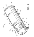
- the present invention is directed to an airbag inflator assembly generally represented by the reference numeral 10.
- the inflator assembly 10 is for use in an airbag module and comprises an airbag inflator 12 having an elongated cylindrical sidewall 15 defining a plurality of gas exhaust ports 16, and an inflator attachment 17 including a sleeve 18 that receives and supports the sidewall 15 of the airbag inflator 12.
- the airbag inflator 12 contains a gas generant system that, when initiated, delivers inflation gas that exits the airbag inflator 12 through the gas exhaust ports 16 for inflating an airbag cushion of an airbag module. Only the sidewall 15 and gas exhaust ports 16 of the airbag inflator 12 are, however, related to the present invention and described in detail.
- the airbag inflator 12 has at an end 13 thereof a flange stop 20 that extends radially outwardly from the sidewall 15.
- the flange stop 20 provides butting engagement with an end 21 of the sleeve 18.
- the sleeve 18 has an inwardly projecting grip 22 to engage the airbag inflator 12.
- the grip is in the form of a snap projection provided as a resilient tab 22 that extends inwardly from the sleeve 18 and faces away from the flange stop 20 and sleeve end 21.
- the resilient tab 22 is snap engaged in one gas exhaust port 24 of the plurality of gas exhaust ports 16 defined by the sidewall 15 of the airbag inflator 12, whereby the gas exhaust port 24 engaged by the tab 22 provides a snap receptor engaged by the snap projection.
- the sleeve 18 includes as a further grip, two spaced-apart pairs of diametrically opposed, inwardly extending protrusions in the form of ribs 29 that grippingly engage the sidewall 15 of the airbag inflator 12.
- the ribs 29 grip the airbag inflator 12 to provide a shake and rattle free engagement between the airbag inflator 12 and the sleeve 18.
- the ribs 29 also provide less contact area between the sleeve 18 and the airbag inflator 12 and, therefore, less frictional resistance to sliding, making it easier to insert the airbag inflator 12 into the sleeve 18.
- the sleeve 18 substantially surrounds the sidewall 15 of the airbag inflator 12 and also defines at least one gas exhaust outlet 28 positioned adjacent the plurality of gas exhaust ports 16 on the airbag inflator 12.
- the airbag inflator 12 shown is a hybrid type inflator having the plurality of gas exhaust ports 16 located at one end thereof.
- the gas exhaust outlet 28 is similarly located at one end of the sleeve 18.
- the ribs 29 additionally provide spacing from the sidewall 15 to allow inflation gas to exit the gas exhaust ports 16 that are positioned on the lower side of the airbag inflator 12 and covered by the sleeve 18 as shown in the figures.
- the sleeve 18 is made from a suitable material such as steel, for example, and the resilient tab 22 is punched in the sleeve 18.
- the inflator attachment 17 further includes mounts comprising studs 26 extending outwardly from and transversely to the sleeve 18 for securing the inflator attachment 17 and airbag inflator 12 within an airbag module.
- the studs 26 are secured to the sleeve by welding or another suitable method.
- the airbag inflator 12 is simply slid into the sleeve 18 until the sleeve end 21 butts against the flange stop 20 of the airbag inflator 12.
- the inwardly projecting resilient tab 22 is bendable away from the housing 14 of the airbag inflator 12 to allow passage of the airbag inflator 12, and the tab 22 snap engages the gas exhaust port 24 defined by the sidewall 15 of the airbag inflator 12 so that the airbag inflator 12, once inserted into the sleeve 18, is retained therein.
- the butting engagement of the flange stop 20 and sleeve end 21 and the snap engagement of the resilient tab 22 and gas exhaust port 24, in combination secure the airbag inflator 12 within the sleeve 18.
- the airbag inflator 12 and inflator attachment 17 are then ready to be mounted within an airbag module with the studs 26.
- the sleeve 18 is adapted for use with an existing airbag inflator 12.
- the present invention therefore, provides an inflator attachment 17 that easily mounts the airbag inflator 12 within an airbag module.
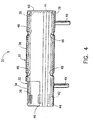
- the airbag inflator assembly 30 comprises an airbag inflator 32 having an elongated cylindrical sidewall 34 defining a plurality of gas exhaust ports 36, and an inflator attachment 37 having a tubular sleeve 38 receiving and supporting the sidewall 34 of the airbag inflator 32.
- the inflator attachment 37 has a stop in the form of an endwall 40 extending across an end 39 of the sleeve 38.
- the endwall 40 which has an access opening 41 to connect the airbag inflator 32 to a remote collision sensor, butts against an end 35 of the airbag inflator 32 to provide a butting engagement between the sleeve 38 and an end 35 of the airbag inflator 32.
- the sleeve 38 also has a grip provided as a snap projection in the form of an inwardly extending resilient tab 42 that faces the endwall 40 and is snap engaged in a snap receptor comprising one gas exhaust port 44 of the plurality of gas exhaust ports 36 defined by the sidewall 34 of the airbag inflator 32.
- the airbag inflator 32 once inserted into the sleeve 38, is retained in the sleeve 38 by the snap engagement between the resilient tab 42 and the gas exhaust port 44 which, in combination with the butting engagement between the endwall 40 and the end 35 of the inflator housing 33, secures the airbag inflator 32 within the sleeve 38.
- the sleeve 38 also defines a gas exhaust outlet 46 positioned adjacent the plurality of gas exhaust ports 36 on the airbag inflator 32, and the grip also includes two spaced-apart pairs of diametrically opposed, inwardly extending protrusions in the form of ribs 48 that grippingly engage the sidewall 34 of the airbag inflator 32, similar to sleeve 18 described above.
- Two studs 49 extending outwardly from and transversely to the sleeve 38 are provided as mounts for securing the inflator attachment 37 and airbag inflator 32 within an airbag module.
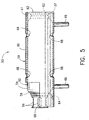
- the inflator assembly 50 comprises an airbag inflator 52 and an inflator attachment 59.
- the airbag inflator 52 has an elongated generally cylindrical sidewall 54 defining a plurality of gas exhaust ports 56 and a tapered neck 58 between the sidewall 54 and the gas exhaust ports 56.
- the inflator attachment 59 includes a tubular sleeve 60 receiving and supporting the sidewall 54 of the airbag inflator 52, and a stop in the form of an endwall 62 located at an end 61 of the sleeve 60.
- the endwall 62 which has an access opening 63 to connect the airbag inflator 52 to a remote collision sensor, butts against and end 57 of the airbag inflator 52 to provide a butting engagement between the sleeve 60 and the airbag inflator 52.
- the sleeve 60 also has a grip provided as a snap projection in the form of an inwardly extending resilient tab 64 that faces the endwall 62.
- the tapered neck 58 of the sidewall 54 of the airbag inflator 52 provides a snap receptor, which is snap engaged by the resilient tab 64.
- the airbag inflator 52 once inserted into the sleeve 60, is retained in the sleeve 60 by a snap engagement between the tab 64 and the tapered neck 58 which, in combination with the butting engagement between the endwall stop 62 and the end 55 of the inflator housing 53, secures the airbag inflator 52 within the sleeve 60.
- the sleeve 60 also defines a gas exhaust outlet 66 positioned adjacent the plurality of gas exhaust ports 56 on the airbag inflator 52 .
- the grip of the sleeve 60 additionally includes two spaced-apart pairs of diametrically opposed, inwardly extending protrusions in the form of ribs 68 that grippingly engage the sidewall 54 of the airbag inflator 52.
- Two mounts comprising studs 69 extend outwardly from and transversely to the sleeve 60 for securing the inflator attachment 59 and airbag inflator 52 within an airbag module.
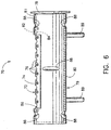
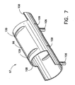
- the inflator assembly 70 comprises an airbag inflator 72 having an elongated cylindrical sidewall 74 defining a plurality of gas exhaust ports 76, and a flange stop 78 located at an end thereof and extending radially outwardly from the sidewall 74.
- the airbag inflator 72 is a pyrotechnic type inflator having the plurality of gas exhaust ports 76 distributed substantially along its entire length.
- An inflator attachment 79 includes a tubular sleeve 80 receiving the sidewall 74 of the airbag inflator 72 with the flange stop 78 of the airbag inflator 72 butting against an end 81 of the sleeve 80 to provide a butting engagement.
- the sleeve 80 also has a grip provided as a snap projection in the form of an inwardly extending resilient tab 82 that faces away from the flange stop 78 and is snap engaged in snap receptor comprising a gas exhaust port 84 of the plurality of gas exhaust ports 76 defined by the sidewall 74 of the airbag inflator 72.
- the airbag inflator 72 once inserted into the sleeve 80, is prevented from being pulled out of the sleeve 80 by a snap engagement between the resilient tab 82 and the gas exhaust port 84, which in combination with the butting engagement between the flange stop 78 and the end 81 of the sleeve 80, secures the airbag inflator 72 within the sleeve 80.
- the sleeve 80 also defines an elongated gas exhaust outlet 86 extending almost the length of the sleeve 80 and positioned adjacent the plurality of gas exhaust ports 76 defined by the sidewall of the airbag inflator 72 .
- the grip of the sleeve 80 further includes three spaced-apart pairs of diametrically opposed inwardly extending protrusions comprising ribs 88 that grippingly engage the sidewall 74 of the airbag inflator 72.
- Two mounts comprising studs 89 extend outwardly from and transversely to the sleeve 80, opposite the gas outlet 86 , for securing the inflator attachment 79 and inflator 72 within an airbag module.
- the inflator assembly 90 comprises an airbag inflator 92 having an elongated cylindrical sidewall 95 defining a plurality of gas exhaust ports 96, and an inflator attachment 97 including a sleeve 98 that receives and supports the sidewall 95 of the airbag inflator 92.
- the sleeve 98 includes a grip in the form of two spaced-apart pairs of diametrically opposed, inwardly extending protrusions provided as ribs 109 that grippingly engage the sidewall 95 of the airbag inflator 92 to secure the inflator within the sleeve.
- the ribs 109 also provide a shake and rattle free engagement between the airbag inflator 92 and the sleeve 98.
- the sleeve 98 substantially surrounds the sidewall 95 of the airbag inflator 92 and also defines gas exhaust outlets 108 at both ends of the sleeve.
- the gas exhaust outlets 108 are positioned so that one of the outlets is located adjacent the plurality of gas exhaust ports 96 on the airbag inflator 92 no matter which side of the sleeve 98 the inflator is inserted into.
- the ribs 109 additionally provide spacing from the sidewall 95 to allow inflation gas to exit the gas exhaust ports 96 that are positioned on the lower side of the airbag inflator 92 and covered by the sleeve 98 as shown in the figures.
- the inflator attachment 97 further includes mounts comprising studs 106 extending outwardly from and transversely to the sleeve 98 for securing the inflator attachment 97 and airbag inflator 92 within an airbag module.
- the studs 106 are secured to the sleeve by welding or another suitable method.
- the airbag inflator 92 is press fit into the sleeve 98 until a sleeve end 101 butts against a flange stop 100 of the airbag inflator 92. It should be noted that there is an extremely tight fit between the two spaced-apart pairs of diametrically opposed, inwardly extending grips in the form of ribs 109 and the sidewall 95 of the airbag inflator 92, and that the sleeve can be provided with a thicker sidewall than the sleeves of FIGS. 1 - 6 to increase the rigidity of the sleeve.
- the two spaced-apart pairs of diametrically opposed, inwardly extending ribs 109 are sized and adapted to more tightly grip the sidewall 95 of the airbag inflator 92 than the inwardly projecting protrusions of the sleeves of FIGS. 1 - 6.
- the inside diameter of the protrusions of the sleeve of FIGS. 1 - 6 are about equal to the outside diameter of the sidewall of the airbag inflator, while the inside diameter of the ribs 109 is smaller than the outside diameter of the sidewall 95 of the inflator 92. This permits all of the gripping engagement to be achieved by the ribs 109, rather than by a combination of ribs and snap engagement.
- the ribs 109 grippingly engage the sidewall 95 of the airbag inflator 92 so that the airbag inflator 92, once inserted into the sleeve 98, is retained therein.
- the airbag inflator 92 and inflator attachment 97 are then ready to be mounted within an airbag module with the studs 106.
- the sleeve 98 may also include an endwall similar to the endwall 40 of the sleeve 38 of FIG. 4. The endwall would provide a butting engagement between the sleeve 98 and the airbag inflator 92.
- the sleeve may include more than one snap projection and the snap projection comprising the resilient tab may alternatively comprise an inwardly extending dimple that is able to slide over the sidewall of the inflator and snap engage a snap receptor of the inflator.
- the sleeve may alternatively include one or more than two mounts, and the mounts may comprise suitable fasteners other than studs such as a flat projecting bracket, for example.
- the sleeve may include more than two or three pairs of inwardly projecting protrusions for gripping the inflator, and the protrusions may comprise dimples, for example, in place of ribs.
Landscapes
- Engineering & Computer Science (AREA)
- Mechanical Engineering (AREA)
- Air Bags (AREA)
Claims (20)
- Dispositif d'attache de gonfleur (17) pour monter un gonfleur d'airbag (12) qui inclut une paroi latérale allongée (15), le dispositif d'attache de gonfleur comprenant :un manchon (18) d'une taille et d'une forme propre à recevoir le gonfleur en relation de butée et à supporter la paroi latérale du gonfleur, au moins une monture (26) s'étendant vers l'extérieur depuis le manchon pour fixer le dispositif d'attache de gonfleur et le gonfleur d'airbag dans un module d'airbag, le manchon ayant au moins un élément de saisie en projection vers l'intérieur, caractérisé en ce que ledit élément de saisie comprend une languette élastique (22) susceptible d'être fléchi vers l'extérieur pour permettre le passage de la paroi latérale du gonfleur d'airbag jusque dans le manchon et pour engager ensuite le gonfleur d'airbag de telle façon que, une fois introduit dans le manchon, le gonfleur est retenu dans le manchon par ledit élément de saisie en projection vers l'intérieur et par l'engagement de butée contre le manchon et le gonfleur d'airbag.
- Dispositif d'attache de gonfleur selon la revendication 1, destiné à être utilisé avec un gonfleur d'airbag (12) ayant une paroi latérale (15) définissant un récepteur à encliquetage sous la forme d'un orifice d'échappement de gaz afin de recevoir ladite languette élastique (22) par engagement d'encliquetage.
- Dispositif d'attache de gonfleur selon l'une ou l'autre des revendications 1 et 2, incluant en outre une pluralité de projections écartées les unes des autres (29), qui s'étendent vers l'intérieur depuis le manchon (18) et d'une taille propre à engager en la saisissant la paroi latérale (15) du gonfleur d'airbag (12).
- Dispositif d'attache de gonfleur selon la revendication 3, dans lequel la pluralité de projections écartées les unes des autres comprennent au moins deux paires écartées de nervures diamétralement opposées (29).
- Dispositif d'attache de gonfleur selon l'une quelconque des revendications précédentes, dans lequel le manchon (18) est conformé de manière à entourer sensiblement le gonfleur d'airbag (12) et définit au moins une sortie d'échappement de gaz (28) positionnée pour exposer au moins un orifice d'échappement de gaz (16) défini par la paroi latérale (15) du gonfleur d'airbag lorsque le gonfleur est retenu à l'intérieur du manchon.
- Dispositif d'attache de gonfleur selon l'une quelconque des revendications précédentes, dans lequel la monture (26) comprend une tige s'étendant généralement transversalement par rapport au manchon (18) et vers l'extérieur de celui-ci.
- Dispositif d'attache de gonfleur selon l'une quelconque des revendications précédentes, dans lequel le manchon (18) a une paroi terminale (40) pour venir buter contre le gonfleur d'airbag (32) quand le gonfleur est reçu dans le manchon.
- Ensemble de gonfleur d'airbag (10) destiné à être utilisé dans un module d'airbag, l'ensemble de gonfleur d'airbag comprenantcaractérisé parun gonfleur d'airbag (12) ayant une paroi latérale allongée (15) ;un dispositif d'attache de gonfleur (17) ayant manchon (18) qui reçoit et qui supporte la paroi latérale allongée du gonfleur d'airbag ;au moins une monture (26) qui s'étend depuis le manchon du dispositif d'attache de gonfleur pour fixer le dispositif d'attache de gonfleur et le gonfleur d'airbag à l'intérieur d'un module d'airbag,
au moins un arrêt (20, 40) sur l'un des éléments parmi le gonfleur d'airbag et le dispositif d'attache d'airbag, entraínant un engagement de butée entre le gonfleur d'airbag et le dispositif d'attache d'airbag ; et
au moins une projection à encliquetage (22, 64) sous la forme d'une languette élastique sur l'un des éléments parmi le gonfleur d'airbag et le dispositif d'attache d'airbag, en engagement d'encliquetage avec au moins un récepteur à encliquetage (24, 58) sur l'autre de ces éléments, tels que l'engagement de butée et l'engagement d'encliquetage retiennent le gonfleur d'airbag dans le manchon. - Ensemble de gonfleur d'airbag selon la revendication 8, dans lequel le récepteur à encliquetage (24, 58) est formé par le gonfleur d'airbag (12, 52) et la projection à encliquetage (22, 64) est située sur le dispositif d'attache de gonfleur (17).
- Ensemble de gonfleur d'airbag selon la revendication 9, dans lequel la languette élastique (22) s'étend vers l'intérieur depuis le manchon (18) du dispositif d'attache de gonfleur (17) et le récepteur à encliquetage comprend un orifice d'échappement de gaz (24) défini par la paroi latérale (15) du gonfleur d'airbag et recevant la languette élastique.
- Ensemble de gonfleur d'airbag selon la revendication 9, dans lequel la languette élastique (64) s'étend vers l'intérieur depuis le manchon (60) du dispositif d'attache de gonfleur (59) et le récepteur encliquetage comprend un étranglement effilé (58) défini par la paroi latérale (54) du gonfleur d'airbag (52) et engagé par la languette élastique.
- Ensemble de gonfleur d'airbag selon l'une quelconque des revendications 8 à 11, dans lequel l'arrêt (20) est situé sur le gonfleur d'airbag (12).
- Ensemble de gonfleur d'airbag selon la revendication 12, dans lequel l'arrêt comprend un arrêt en forme de bride (20) situé à une extrémité (13) du gonfleur d'airbag, s'étendant vers l'extérieur depuis la paroi latérale (15) et en butée contre le manchon (18).
- Ensemble de gonfleur d'airbag selon l'une quelconque des revendications 8 à 11, dans lequel l'arrêt (40) est situé sur le manchon (38).
- Ensemble de gonfleur d'airbag selon la revendication 14, dans lequel l'arrêt comprend une paroi terminale (40) située à une extrémité (39) du manchon (38) du dispositif d'attache de gonfleur (37) et en butée contre le gonfleur d'airbag (32).
- Ensemble de gonfleur d'airbag selon l'une quelconque des revendications 8 à 15, durant lequel le dispositif d'attache de gonfleur (17) inclut encore une pluralité de projections écartées les unes des autres (29) qui s'étendent vers l'intérieur depuis le manchon (18) et qui engagent en la saisissant la paroi latérale (15) du gonfleur d'airbag (12).
- Ensemble de gonfleur d'airbag selon la revendication 16, dans lequel la pluralité de projections espacées les unes des autres (29) comprennent au moins deux paires écartées de nervures diamétralement opposées, qui se projettent vers l'intérieur depuis le manchon (18) et qui engagent en la saisissant la paroi latérale (15) du gonfleur d'airbag (12).
- Ensemble de gonfleur d'airbag selon l'une quelconque des revendications 8 à 17, dans lequel le manchon (18) du dispositif d'attache de gonfleur (17) entoure sensiblement la paroi latérale (15) du gonfleur d'airbag (12) et définit au moins une sortie d'échappement de gaz (28) exposant au moins un orifice d'échappement de gaz (16) défini par la paroi latérale du gonfleur d'airbag.
- Ensemble de gonfleur d'airbag selon l'une quelconque des revendications 8 à 18, dans lequel la monture comprend une tige qui s'étend généralement transversalement par rapport au manchon et vers l'extérieur de celui-ci.
- Ensemble de gonfleur d'airbag selon l'une quelconque des revendications 8 à 19, dans lequel la projection à encliquetage comprend une languette élastique (22, 42, 64) qui s'étend vers l'intérieur depuis le manchon (18, 38, 60) et qui est détournée de l'extrémité du manchon depuis laquelle le gonfleur (12, 32, 52) est introduit.
Applications Claiming Priority (4)
| Application Number | Priority Date | Filing Date | Title |
|---|---|---|---|
| US58343896A | 1996-01-05 | 1996-01-05 | |
| US583438 | 1996-01-05 | ||
| US643450 | 1996-05-08 | ||
| US08/643,450 US5611563A (en) | 1996-01-05 | 1996-05-08 | Airbag inflator attachment with snap-in sleeve |
Publications (3)
| Publication Number | Publication Date |
|---|---|
| EP0782943A2 EP0782943A2 (fr) | 1997-07-09 |
| EP0782943A3 EP0782943A3 (fr) | 1999-04-07 |
| EP0782943B1 true EP0782943B1 (fr) | 2003-04-16 |
Family
ID=27078804
Family Applications (1)
| Application Number | Title | Priority Date | Filing Date |
|---|---|---|---|
| EP97300011A Expired - Lifetime EP0782943B1 (fr) | 1996-01-05 | 1997-01-02 | Fixation d'un gonfleur de coussin de sécurité par enclenchement dans un manchon adéquat |
Country Status (4)
| Country | Link |
|---|---|
| US (1) | US5611563A (fr) |
| EP (1) | EP0782943B1 (fr) |
| JP (1) | JP3039217U (fr) |
| DE (1) | DE69720812T2 (fr) |
Families Citing this family (32)
| Publication number | Priority date | Publication date | Assignee | Title |
|---|---|---|---|---|
| US5704634A (en) * | 1996-02-15 | 1998-01-06 | Trw Vehicle Safety Systems Inc. | Side impact air bag module |
| US5918898A (en) * | 1996-02-15 | 1999-07-06 | Trw Vehicle Safety Systems Inc. | Side impact air bag module |
| DE29606724U1 (de) * | 1996-04-15 | 1996-11-14 | Trw Occupant Restraint Systems Gmbh, 73551 Alfdorf | Gassack-Modul für ein Fahrzeug |
| US5687988A (en) * | 1996-07-17 | 1997-11-18 | Morton International, Inc. | Airbag cushion and airbag inflator retention device |
| US5803486A (en) * | 1996-12-17 | 1998-09-08 | General Motors Corporation | Air bag module with mounting and diffuser bracket |
| JP2000289510A (ja) * | 1999-04-02 | 2000-10-17 | T S Tec Kk | エアーバッグ装置装備シート |
| JP3528818B2 (ja) | 2000-12-27 | 2004-05-24 | トヨタ自動車株式会社 | エアバッグ装置 |
| JP3903801B2 (ja) * | 2002-01-28 | 2007-04-11 | タカタ株式会社 | インフレータの固定方法及び構造並びにエアバッグ装置 |
| JP3922073B2 (ja) * | 2002-04-02 | 2007-05-30 | タカタ株式会社 | 外面展開型エアバッグ装置 |
| US6945554B2 (en) * | 2002-08-26 | 2005-09-20 | Autoliv Asp, Inc. | Inflator press fit housing for inflatable curtains |
| US6976700B2 (en) * | 2002-11-12 | 2005-12-20 | Trw Vehicle Safety Systems Inc. | Air bag inflator bracket |
| US7063350B2 (en) * | 2003-09-23 | 2006-06-20 | Autoliv Asp, Inc. | Dual chamber side airbag apparatus and method |
| US20050206135A1 (en) * | 2003-10-27 | 2005-09-22 | Nelson James E | Curtain airbag handling device |
| US7125038B2 (en) * | 2003-10-27 | 2006-10-24 | Autoliv Asp, Inc. | Twist prevention apparatus and method for an inflatable airbag curtain |
| JP4281644B2 (ja) * | 2003-11-21 | 2009-06-17 | 豊田合成株式会社 | インフレーター |
| US7370884B2 (en) * | 2004-03-02 | 2008-05-13 | Autoliv Asp, Inc. | Expanding airbag inflator housing |
| DE102004022732B3 (de) * | 2004-05-07 | 2005-12-29 | Trw Automotive Gmbh | Baugruppe aus einem Gehäuse und einem Gasgenerator für ein Seitengassackmodul |
| DE102005049156A1 (de) * | 2005-10-14 | 2007-04-19 | GM Global Technology Operations, Inc., Detroit | Verfahren zum Befestigen eines Gasgenerators in einer Gasgeneratorkammer und Gehäuse mit einer Gasgeneratorkammer |
| JP4853215B2 (ja) * | 2006-10-10 | 2012-01-11 | 豊田合成株式会社 | エアバッグ装置 |
| US7699340B2 (en) * | 2006-10-10 | 2010-04-20 | Toyoda Gosei Co., Ltd. | Air bag apparatus |
| EP1923276B1 (fr) * | 2006-11-15 | 2008-09-10 | Delphi Technologies, Inc. | Modul de sac gonflable |
| JP5154840B2 (ja) * | 2007-06-06 | 2013-02-27 | オートリブ ディベロップメント エービー | インフレータ付きハウジングおよびこれを備えた車両用サイドエアバッグ装置 |
| US7938436B2 (en) * | 2008-01-29 | 2011-05-10 | Autoliv Asp, Inc. | Slide-on inflator housing |
| DE102008039181A1 (de) * | 2008-08-20 | 2010-03-04 | Takata-Petri Ag | Airbagmodul mit einem Gassack und einem an einem Modulgehäuse befestigbaren Rohrgasgenerator |
| DE102008056946A1 (de) * | 2008-11-07 | 2010-05-12 | Takata-Petri Ag | Airbagmodul mit einem Gassack und einem an einem Modulgehäuse befestigbaren Rohrgasgenerator |
| JP6494105B2 (ja) * | 2015-08-06 | 2019-04-03 | 本田技研工業株式会社 | インフレータ及びエアバッグ装置 |
| JP6760181B2 (ja) * | 2017-03-30 | 2020-09-23 | 豊田合成株式会社 | エアバッグ装置 |
| US10518736B2 (en) | 2017-11-02 | 2019-12-31 | The Boeing Company | Thrust neutral inflation assembly and methods of use |
| DE102018105445A1 (de) * | 2018-03-09 | 2019-09-12 | Benteler Steel/Tube Gmbh | Gehäuse eines Gasgeneratormoduls für ein Airbagsystem eines Kraftfahrzeuges |
| DE102020104986A1 (de) * | 2020-02-26 | 2021-08-26 | Zf Automotive Germany Gmbh | Gassackmodul, Verfahren zum Austausch eines Gasgenerators eines Gassackmoduls sowie Verfahren zur Herstellung eines Gassackmoduls |
| US11708043B2 (en) * | 2021-04-20 | 2023-07-25 | Autoliv Asp, Inc. | Inflator bracket |
| US11718263B2 (en) * | 2021-09-02 | 2023-08-08 | ZF Passive Safety Systems US Inc. | Fill tube adaptor for inflator |
Family Cites Families (5)
| Publication number | Priority date | Publication date | Assignee | Title |
|---|---|---|---|---|
| US5308108A (en) * | 1992-10-26 | 1994-05-03 | Allied-Signal Inc. | Manifold or retainer for a gas generator |
| DE4415374A1 (de) * | 1994-05-02 | 1995-11-09 | Trw Repa Gmbh | Gassack-Modul |
| US5468012A (en) * | 1994-06-13 | 1995-11-21 | Trw Vehicle Safety Systems Inc. | Air bag module |
| US5458364A (en) * | 1994-08-22 | 1995-10-17 | Morton International, Inc. | Inflator secured in diffuser housing of airbag module assembly by locking end cap |
| US5498029A (en) * | 1995-01-19 | 1996-03-12 | Morton International, Inc. | Toothed inflator adapter for an airbag assembly |
-
1996
- 1996-05-08 US US08/643,450 patent/US5611563A/en not_active Expired - Lifetime
-
1997
- 1997-01-02 EP EP97300011A patent/EP0782943B1/fr not_active Expired - Lifetime
- 1997-01-02 DE DE69720812T patent/DE69720812T2/de not_active Expired - Lifetime
- 1997-01-06 JP JP1997000005U patent/JP3039217U/ja not_active Expired - Lifetime
Also Published As
| Publication number | Publication date |
|---|---|
| EP0782943A2 (fr) | 1997-07-09 |
| DE69720812D1 (de) | 2003-05-22 |
| DE69720812T2 (de) | 2004-03-04 |
| JP3039217U (ja) | 1997-07-15 |
| US5611563A (en) | 1997-03-18 |
| EP0782943A3 (fr) | 1999-04-07 |
Similar Documents
| Publication | Publication Date | Title |
|---|---|---|
| EP0782943B1 (fr) | Fixation d'un gonfleur de coussin de sécurité par enclenchement dans un manchon adéquat | |
| JP2604972B2 (ja) | 膨張式クッションを反応容器部材に取付ける装置及び方法 | |
| US5407226A (en) | Inflatable restraint system reaction canister | |
| US5620200A (en) | Airbag module reaction canister endwall with airbag inflator mount | |
| US5556127A (en) | Seat mounted side impact module | |
| EP0620140B2 (fr) | Boítier de réaction d'un système de retenue gonflable | |
| US6161865A (en) | Interlocking airbag attachment and module assembly | |
| EP0722862B1 (fr) | Couvercle pour l'ouverture d'un panneau dans un système de sécurité à sac gonflable | |
| JP2522623B2 (ja) | 車輌乗員拘束装置 | |
| US5687988A (en) | Airbag cushion and airbag inflator retention device | |
| US20050029780A1 (en) | Head-protecting airbag device | |
| US5752715A (en) | Airbag module diffuser | |
| JPH08230596A (ja) | 同乗者用エアバック拘束装置 | |
| US5615907A (en) | Airbag inflator retention tabs | |
| JPH09164895A (ja) | 自動車用エアバッグモジュール | |
| US5788266A (en) | Simplified airbag module housing | |
| US5431433A (en) | Fastenerless tethered deployment door for passenger-side airbag module | |
| US5511818A (en) | Passenger side airbag module | |
| EP0679556B1 (fr) | Assemblage d'un gonfleur d'un air-bag pour installation dans le tableau de bord d'un véhicule | |
| US5560643A (en) | Airbag module with clamped attachment of airbag cushion | |
| US5568936A (en) | Airbag module case for side impact airbag module | |
| EP0714816B1 (fr) | Couvercle de déploiement pour utilisation dans un dispositif de retenue d'un occupant de véhicule | |
| US6364343B1 (en) | Grab handle bracket/airbag igniter retainer | |
| WO2004067337A1 (fr) | Airbag | |
| US5419584A (en) | Air bag retention clip |
Legal Events
| Date | Code | Title | Description |
|---|---|---|---|
| PUAI | Public reference made under article 153(3) epc to a published international application that has entered the european phase |
Free format text: ORIGINAL CODE: 0009012 |
|
| AK | Designated contracting states |
Kind code of ref document: A2 Designated state(s): DE FR GB IT |
|
| 17P | Request for examination filed |
Effective date: 19981203 |
|
| PUAL | Search report despatched |
Free format text: ORIGINAL CODE: 0009013 |
|
| AK | Designated contracting states |
Kind code of ref document: A3 Designated state(s): DE FR GB IT |
|
| 17Q | First examination report despatched |
Effective date: 20010919 |
|
| GRAG | Despatch of communication of intention to grant |
Free format text: ORIGINAL CODE: EPIDOS AGRA |
|
| GRAG | Despatch of communication of intention to grant |
Free format text: ORIGINAL CODE: EPIDOS AGRA |
|
| GRAG | Despatch of communication of intention to grant |
Free format text: ORIGINAL CODE: EPIDOS AGRA |
|
| GRAH | Despatch of communication of intention to grant a patent |
Free format text: ORIGINAL CODE: EPIDOS IGRA |
|
| GRAH | Despatch of communication of intention to grant a patent |
Free format text: ORIGINAL CODE: EPIDOS IGRA |
|
| GRAA | (expected) grant |
Free format text: ORIGINAL CODE: 0009210 |
|
| RAP1 | Party data changed (applicant data changed or rights of an application transferred) |
Owner name: AUTOLIV ASP, INC. |
|
| AK | Designated contracting states |
Designated state(s): DE FR GB IT |
|
| PG25 | Lapsed in a contracting state [announced via postgrant information from national office to epo] |
Ref country code: IT Free format text: LAPSE BECAUSE OF FAILURE TO SUBMIT A TRANSLATION OF THE DESCRIPTION OR TO PAY THE FEE WITHIN THE PRESCRIBED TIME-LIMIT;WARNING: LAPSES OF ITALIAN PATENTS WITH EFFECTIVE DATE BEFORE 2007 MAY HAVE OCCURRED AT ANY TIME BEFORE 2007. THE CORRECT EFFECTIVE DATE MAY BE DIFFERENT FROM THE ONE RECORDED. Effective date: 20030416 |
|
| REG | Reference to a national code |
Ref country code: GB Ref legal event code: FG4D |
|
| REF | Corresponds to: |
Ref document number: 69720812 Country of ref document: DE Date of ref document: 20030522 Kind code of ref document: P |
|
| PGFP | Annual fee paid to national office [announced via postgrant information from national office to epo] |
Ref country code: GB Payment date: 20031224 Year of fee payment: 8 |
|
| ET | Fr: translation filed | ||
| PLBE | No opposition filed within time limit |
Free format text: ORIGINAL CODE: 0009261 |
|
| STAA | Information on the status of an ep patent application or granted ep patent |
Free format text: STATUS: NO OPPOSITION FILED WITHIN TIME LIMIT |
|
| 26N | No opposition filed |
Effective date: 20040119 |
|
| PG25 | Lapsed in a contracting state [announced via postgrant information from national office to epo] |
Ref country code: GB Free format text: LAPSE BECAUSE OF NON-PAYMENT OF DUE FEES Effective date: 20050102 |
|
| GBPC | Gb: european patent ceased through non-payment of renewal fee |
Effective date: 20050102 |
|
| PGFP | Annual fee paid to national office [announced via postgrant information from national office to epo] |
Ref country code: FR Payment date: 20081124 Year of fee payment: 13 |
|
| REG | Reference to a national code |
Ref country code: FR Ref legal event code: ST Effective date: 20100930 |
|
| PG25 | Lapsed in a contracting state [announced via postgrant information from national office to epo] |
Ref country code: FR Free format text: LAPSE BECAUSE OF NON-PAYMENT OF DUE FEES Effective date: 20100201 |
|
| PGFP | Annual fee paid to national office [announced via postgrant information from national office to epo] |
Ref country code: DE Payment date: 20101116 Year of fee payment: 15 |
|
| PG25 | Lapsed in a contracting state [announced via postgrant information from national office to epo] |
Ref country code: DE Free format text: LAPSE BECAUSE OF NON-PAYMENT OF DUE FEES Effective date: 20120801 |
|
| REG | Reference to a national code |
Ref country code: DE Ref legal event code: R119 Ref document number: 69720812 Country of ref document: DE Effective date: 20120801 |