EP0783089A2 - Brûleur sous forme d'un cÔne - Google Patents
Brûleur sous forme d'un cÔne Download PDFInfo
- Publication number
- EP0783089A2 EP0783089A2 EP96810821A EP96810821A EP0783089A2 EP 0783089 A2 EP0783089 A2 EP 0783089A2 EP 96810821 A EP96810821 A EP 96810821A EP 96810821 A EP96810821 A EP 96810821A EP 0783089 A2 EP0783089 A2 EP 0783089A2
- Authority
- EP
- European Patent Office
- Prior art keywords
- burner
- cone
- outlet diffuser
- fuel
- air inlet
- Prior art date
- Legal status (The legal status is an assumption and is not a legal conclusion. Google has not performed a legal analysis and makes no representation as to the accuracy of the status listed.)
- Granted
Links
Images


Classifications
-
- F—MECHANICAL ENGINEERING; LIGHTING; HEATING; WEAPONS; BLASTING
- F23—COMBUSTION APPARATUS; COMBUSTION PROCESSES
- F23C—METHODS OR APPARATUS FOR COMBUSTION USING FLUID FUEL OR SOLID FUEL SUSPENDED IN A CARRIER GAS OR AIR
- F23C7/00—Combustion apparatus characterised by arrangements for air supply
- F23C7/002—Combustion apparatus characterised by arrangements for air supply the air being submitted to a rotary or spinning motion
-
- F—MECHANICAL ENGINEERING; LIGHTING; HEATING; WEAPONS; BLASTING
- F23—COMBUSTION APPARATUS; COMBUSTION PROCESSES
- F23C—METHODS OR APPARATUS FOR COMBUSTION USING FLUID FUEL OR SOLID FUEL SUSPENDED IN A CARRIER GAS OR AIR
- F23C15/00—Apparatus in which combustion takes place in pulses influenced by acoustic resonance in a gas mass
-
- F—MECHANICAL ENGINEERING; LIGHTING; HEATING; WEAPONS; BLASTING
- F23—COMBUSTION APPARATUS; COMBUSTION PROCESSES
- F23D—BURNERS
- F23D17/00—Burners for combustion simultaneously or alternately of gaseous or liquid or pulverulent fuel
- F23D17/002—Burners for combustion simultaneously or alternately of gaseous or liquid or pulverulent fuel gaseous or liquid fuel
-
- F—MECHANICAL ENGINEERING; LIGHTING; HEATING; WEAPONS; BLASTING
- F23—COMBUSTION APPARATUS; COMBUSTION PROCESSES
- F23R—GENERATING COMBUSTION PRODUCTS OF HIGH PRESSURE OR HIGH VELOCITY, e.g. GAS-TURBINE COMBUSTION CHAMBERS
- F23R3/00—Continuous combustion chambers using liquid or gaseous fuel
- F23R3/02—Continuous combustion chambers using liquid or gaseous fuel characterised by the air-flow or gas-flow configuration
- F23R3/04—Air inlet arrangements
- F23R3/10—Air inlet arrangements for primary air
- F23R3/12—Air inlet arrangements for primary air inducing a vortex
-
- F—MECHANICAL ENGINEERING; LIGHTING; HEATING; WEAPONS; BLASTING
- F23—COMBUSTION APPARATUS; COMBUSTION PROCESSES
- F23R—GENERATING COMBUSTION PRODUCTS OF HIGH PRESSURE OR HIGH VELOCITY, e.g. GAS-TURBINE COMBUSTION CHAMBERS
- F23R3/00—Continuous combustion chambers using liquid or gaseous fuel
- F23R3/28—Continuous combustion chambers using liquid or gaseous fuel characterised by the fuel supply
- F23R3/283—Attaching or cooling of fuel injecting means including supports for fuel injectors, stems, or lances
-
- F—MECHANICAL ENGINEERING; LIGHTING; HEATING; WEAPONS; BLASTING
- F23—COMBUSTION APPARATUS; COMBUSTION PROCESSES
- F23R—GENERATING COMBUSTION PRODUCTS OF HIGH PRESSURE OR HIGH VELOCITY, e.g. GAS-TURBINE COMBUSTION CHAMBERS
- F23R3/00—Continuous combustion chambers using liquid or gaseous fuel
- F23R3/28—Continuous combustion chambers using liquid or gaseous fuel characterised by the fuel supply
- F23R3/30—Continuous combustion chambers using liquid or gaseous fuel characterised by the fuel supply comprising fuel prevapourising devices
-
- F—MECHANICAL ENGINEERING; LIGHTING; HEATING; WEAPONS; BLASTING
- F23—COMBUSTION APPARATUS; COMBUSTION PROCESSES
- F23C—METHODS OR APPARATUS FOR COMBUSTION USING FLUID FUEL OR SOLID FUEL SUSPENDED IN A CARRIER GAS OR AIR
- F23C2900/00—Special features of, or arrangements for combustion apparatus using fluid fuels or solid fuels suspended in air; Combustion processes therefor
- F23C2900/07002—Premix burners with air inlet slots obtained between offset curved wall surfaces, e.g. double cone burners
Definitions
- the invention relates to a cone burner for gaseous and / or liquid fuels, according to the preamble of claim 1.
- EP-B1-0321809 discloses a double-cone burner suitable for the combustion of gaseous and / or liquid fuels.
- This burner consists of two hollow partial cone bodies that complement one another and have tangential air inlet slots.
- a line for gaseous fuel is arranged at the radial end of each air inlet slot. The gaseous fuel is therefore mixed into the tangentially flowing combustion air within the air inlet slots, specifically in the entire interior of the burner. If liquid fuel is used, it is injected into the burner interior via a centrally arranged nozzle.
- a central backflow zone of the combustion mixture is formed.
- an average fuel profile over the burner cross-section has already been achieved on average.
- the combustion mixture is ignited at the top of the return flow zone, so that a stable flame front is created there.
- the sudden expansion of the area to the combustion chamber also creates an outer recirculation area, which also contributes to flame stabilization.
- the fuel concentration is reduced in the axial direction by the tangentially introduced combustion air, so that a well-premixed fuel mixture is created.
- gaseous fuel is used, the distance from the mixing points of the fuel arranged in the downstream region of the burner to the flame is only very small. For this reason, the fuel mixture present there, which has not yet been completely homogenized in terms of time and location, leads to increased production of nitrogen oxides and carbon monoxide.
- the invention tries to avoid all of these disadvantages. It is based on the task of creating a cone burner for gaseous and / or liquid fuels which has a reduced NOx and CO emission.
- the partial cone bodies have a common outlet diffuser at their downstream end.
- the partial cone bodies have a transition area to the outlet diffuser, in which the size of the air inlet slots decreases continuously in the direction of flow.
- the outlet diffuser is circular and has no air inlet slots.
- the cone burner now has a circular outlet cross-section to the combustion chamber, which means that, compared to the known double-cone burners, there is no need for cooling air for the sickles used there.
- the outlet diffuser provides a stronger shielding of the reaction zone from the neighboring burners, which results in increased flame stability.
- the diameter of the fuel supply decreases in the direction of flow in the transition area of the partial cone body to the outlet diffuser.
- the gas perforation in the transition area is adjusted according to the local slot width and a uniform distribution of the gaseous fuel in the combustion air is achieved.
- the outlet diffuser has a length of approximately 10 to 25 percent of the total length of the cone burner and has an outlet area which is not greater than 1.3 times a cross-sectional area of the double cone part formed by the partial cone bodies at the beginning of the transition region .
- Such a relatively short diffuser results in a small boundary layer thickness, so that the flame does not kick back in the boundary layer.
- the outlet diffuser has an opening angle which increases continuously in the direction of flow and which initially corresponds to the cone angle of the burner and is continuously larger downstream than this. This stabilizes the wall boundary layer and minimizes the risk of flow separation.
- the drawing shows two exemplary embodiments of the invention using a double-cone burner connected to a combustion chamber.
- the double-cone burner has a burner interior 6 which widens conically in the direction of flow 3. Tangential air inlet slots 7, 8 are formed between the partial cone bodies 1, 2.
- a fuel line 9, 10 for gaseous fuel 11 is arranged on each of the two partial cone bodies 1, 2 and there at the outer end of the air inlet slots 7, 8 (FIG. 1).
- the fuel lines 9, 10 are provided with several, in the entire area of the air inlet slots 7, 8 evenly distributed and formed as openings fuel supply lines 12.
- Both partial cone bodies 1, 2 each have a cylindrical starting part 13, 14, which are also arranged offset from one another.
- the tangential air inlet slots 7, 8 are thus formed on the upstream side over the entire length of the double-cone burner.
- a central liquid fuel nozzle 15 opening into the burner interior 6 is arranged.
- Both partial cone bodies 1, 2 have a flat cone angle 16 formed in the range from 10 ° to 30 °.
- a collar-shaped end plate 18 serving as anchoring for the partial cone bodies 1, 2 is arranged on the double-cone burner.
- a number of bores 19 are formed, through which cooling air 20 for the crescent-shaped ends of the partial cone bodies 1, 2 located immediately upstream of the end plate 18 is discharged to the combustion chamber 17.
- FIG. 3 shows a schematic representation of a double-cone burner according to the invention. For the sake of clarity, only the essential components or the components which have been changed compared to the prior art shown in FIGS. 1 and 2 are shown.
- the two half, hollow partial cone bodies 1, 2 of the burner complement one another to form a body 26 which is designed as a double cone part and which merges downstream into a common, circular outlet diffuser 27.
- a transition region 28 from the double cone part 26 to the outlet diffuser 27 is formed.
- the size of the air inlet slots 7, 8 decreases continuously in the direction of flow 3.
- the burner cross section is continuously expanded, as a result of which the area through which the fuel mixture flows is also larger in the transition region 28 or at least remains constant.
- the outlet diffuser 27 has a length 29 of approximately 15 percent of the total length 30 of the double-burner burner. Its exit surface 31 corresponds approximately to 1.3 times the cross-sectional area 32 at the beginning of the transition region 28. It has an opening angle 33 which is initially equal to the cone angle 16 of the burner and increases continuously in the direction of flow 3.
- transition region 28 to the outlet diffuser 27 is shown enlarged in FIG. 4, as a result of which the arrangement and configuration of the fuel line 9 ending at the downstream end of the transition region 28 become clear.
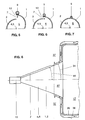
- FIGS. 5 to 7 show three partial cross sections of the double-cone part 26 in its transition region 28. The beginning of FIG. 5, the middle part in FIG. 6 and the end of the transition region 28 in FIG. 7 are shown. In the transition region 28, the diameter of the fuel line 9 and of the openings 12 in the flow direction 3 is reduced. At the end of the transition area 28, the air inlet slots 7, 8 and the openings 12 are completely closed. Neither air inlet slots 7, 8 nor fuel lines 9, 10 are arranged on the circular outlet diffuser 27 that adjoins downstream (FIG. 3).
- the arrangement of the outlet diffuser 27 additionally provides time and space for the mixing in of the gaseous fuel 11 which is only introduced in the downstream region of the double-cone part 26. In this way, an optimal fuel concentration is achieved across the cross-section of the burner. When burning such a homogenized fuel mixture, the NOx and CO emissions are significantly reduced. A reduction in emissions is also achieved when using liquid fuel 21, but the advantage in this case is not that great.
- the flow of the fuel mixture is slightly delayed in the outlet diffuser 27 and is therefore unstable at its center.
- the central backflow zone 24 of the fuel mixture is formed and the conical fuel profile 22 bursts only in the vicinity of the downstream end of the outlet diffuser 27 reached in the combustion chamber 17.
- the boundary layer in its interior does not detach, so that a stable flame front 25 can advantageously only be formed downstream of the double-cone burner.
- the outlet diffuser 27 has an opening angle 34, which is formed equal to the cone angle 16 of the burner (FIG. 8). Due to the simple, straight shape of the outlet diffuser 27, this double-cone burner can be manufactured much lighter and cheaper.
- a cooling air baffle is outside the combustion chamber wall 35 36 arranged, which extends upstream to the outlet diffuser 27 and ends at the downstream end of the air inlet slots 7, 8.
- the outlet diffuser 27 is cooled from the outside with cooling air flowing back in the space between the combustion chamber wall 35 and the cooling air baffle 36, the latter finally opening into a plenum 37 formed upstream of the burner. Because of this convective cooling of the outlet diffuser 27, the operational safety is further improved compared to the first exemplary embodiment.
Landscapes
- Engineering & Computer Science (AREA)
- Chemical & Material Sciences (AREA)
- Combustion & Propulsion (AREA)
- Mechanical Engineering (AREA)
- General Engineering & Computer Science (AREA)
- Pressure-Spray And Ultrasonic-Wave- Spray Burners (AREA)
- Spray-Type Burners (AREA)
Applications Claiming Priority (2)
| Application Number | Priority Date | Filing Date | Title |
|---|---|---|---|
| DE19548853A DE19548853A1 (de) | 1995-12-27 | 1995-12-27 | Kegelbrenner |
| DE19548853 | 1995-12-27 |
Publications (3)
| Publication Number | Publication Date |
|---|---|
| EP0783089A2 true EP0783089A2 (fr) | 1997-07-09 |
| EP0783089A3 EP0783089A3 (fr) | 1998-11-11 |
| EP0783089B1 EP0783089B1 (fr) | 2001-04-11 |
Family
ID=7781504
Family Applications (1)
| Application Number | Title | Priority Date | Filing Date |
|---|---|---|---|
| EP96810821A Expired - Lifetime EP0783089B1 (fr) | 1995-12-27 | 1996-11-25 | Brûleur sous forme d'un cône |
Country Status (5)
| Country | Link |
|---|---|
| US (1) | US5807097A (fr) |
| EP (1) | EP0783089B1 (fr) |
| JP (1) | JP3810502B2 (fr) |
| CN (1) | CN1119560C (fr) |
| DE (2) | DE19548853A1 (fr) |
Cited By (2)
| Publication number | Priority date | Publication date | Assignee | Title |
|---|---|---|---|---|
| WO2013144048A1 (fr) * | 2012-03-29 | 2013-10-03 | Alstom Technology Ltd | Chambre de combustion de turbine à gaz |
| EP2722592A1 (fr) * | 2012-10-22 | 2014-04-23 | Alstom Technology Ltd | Brûleur à multiples cones pour une turbine à gaz |
Families Citing this family (14)
| Publication number | Priority date | Publication date | Assignee | Title |
|---|---|---|---|---|
| EP0924458B1 (fr) * | 1997-12-22 | 2002-08-28 | Alstom | Brûleur |
| RU2167363C2 (ru) * | 1999-05-25 | 2001-05-20 | Открытое акционерное общество "Авиадвигатель" | Горелка с предварительным смешением газового топлива и воздуха |
| EP1217295B1 (fr) * | 2000-12-23 | 2006-08-23 | ALSTOM Technology Ltd | Brûleur pour la génération d'un gaz chaud |
| DE10342763A1 (de) * | 2003-09-16 | 2005-07-07 | BSH Bosch und Siemens Hausgeräte GmbH | Gasbrenner für flüssigen Brennstoff |
| FR2870741B1 (fr) * | 2004-05-25 | 2008-03-14 | Coletica Sa | Phase lamellaires hydratees ou liposomes, contenant une monoamine grasse ou un polymere cationique favorisant la penetration intercellulaire, et composition cosmetique ou pharmaceutique la contenant. |
| EP1817526B1 (fr) * | 2004-11-30 | 2019-03-20 | Ansaldo Energia Switzerland AG | Procédé et dispositif de combustion d'hydrogène dans un brûleur a prémelange |
| USD544090S1 (en) * | 2005-06-03 | 2007-06-05 | Emerson Electric Co. | Radial diffuser |
| FR2915989B1 (fr) * | 2007-05-10 | 2011-05-20 | Saint Gobain Emballage | Injecteur mixte a bas nox |
| CN101852443B (zh) * | 2010-03-15 | 2012-04-18 | 高海华 | 生物质锅炉加氧猛火燃尽装置 |
| US8967985B2 (en) | 2012-11-13 | 2015-03-03 | Roper Pump Company | Metal disk stacked stator with circular rigid support rings |
| CN104566371A (zh) * | 2014-12-15 | 2015-04-29 | 昆山富凌能源利用有限公司 | 一种环保节能燃气灶芯 |
| KR101990767B1 (ko) * | 2017-08-09 | 2019-06-20 | 한국기계연구원 | 이중 원추형 가스터빈용 버너 및 이 버너에 공기를 공급하는 방법 |
| CN109737450B (zh) * | 2018-12-11 | 2019-12-03 | 北京航空航天大学 | 燃烧室燃烧振荡控制装置及燃烧室燃烧振荡控制方法 |
| CN116557908B (zh) * | 2023-02-28 | 2025-09-09 | 中山大学·深圳 | 一种带有气动雾化功能的可变火焰稳定器 |
Citations (1)
| Publication number | Priority date | Publication date | Assignee | Title |
|---|---|---|---|---|
| EP0321809B1 (fr) | 1987-12-21 | 1991-05-15 | BBC Brown Boveri AG | Procédé pour la combustion de combustible liquide dans un brûleur |
Family Cites Families (5)
| Publication number | Priority date | Publication date | Assignee | Title |
|---|---|---|---|---|
| DE3707773C2 (de) * | 1987-03-11 | 1996-09-05 | Bbc Brown Boveri & Cie | Einrichtung zur Prozesswärmeerzeugung |
| CH679692A5 (fr) * | 1989-04-24 | 1992-03-31 | Asea Brown Boveri | |
| ATE124528T1 (de) * | 1990-10-17 | 1995-07-15 | Asea Brown Boveri | Brennkammer einer gasturbine. |
| DE4316474A1 (de) * | 1993-05-17 | 1994-11-24 | Abb Management Ag | Vormischbrenner zum Betrieb einer Brennkraftmaschine, einer Brennkammer einer Gasturbogruppe oder Feuerungsanlage |
| DE4426353A1 (de) * | 1994-07-25 | 1996-02-01 | Abb Research Ltd | Brenner |
-
1995
- 1995-12-27 DE DE19548853A patent/DE19548853A1/de not_active Withdrawn
-
1996
- 1996-11-25 DE DE59606762T patent/DE59606762D1/de not_active Expired - Lifetime
- 1996-11-25 EP EP96810821A patent/EP0783089B1/fr not_active Expired - Lifetime
- 1996-12-04 US US08/760,688 patent/US5807097A/en not_active Expired - Fee Related
- 1996-12-27 JP JP35030796A patent/JP3810502B2/ja not_active Expired - Lifetime
- 1996-12-27 CN CN96121396A patent/CN1119560C/zh not_active Expired - Lifetime
Patent Citations (1)
| Publication number | Priority date | Publication date | Assignee | Title |
|---|---|---|---|---|
| EP0321809B1 (fr) | 1987-12-21 | 1991-05-15 | BBC Brown Boveri AG | Procédé pour la combustion de combustible liquide dans un brûleur |
Cited By (3)
| Publication number | Priority date | Publication date | Assignee | Title |
|---|---|---|---|---|
| WO2013144048A1 (fr) * | 2012-03-29 | 2013-10-03 | Alstom Technology Ltd | Chambre de combustion de turbine à gaz |
| EP2722592A1 (fr) * | 2012-10-22 | 2014-04-23 | Alstom Technology Ltd | Brûleur à multiples cones pour une turbine à gaz |
| US9464810B2 (en) | 2012-10-22 | 2016-10-11 | General Electric Technology Gmbh | Burner including a swirl chamber with slots having different widths |
Also Published As
| Publication number | Publication date |
|---|---|
| JPH09189406A (ja) | 1997-07-22 |
| EP0783089A3 (fr) | 1998-11-11 |
| DE59606762D1 (de) | 2001-05-17 |
| EP0783089B1 (fr) | 2001-04-11 |
| US5807097A (en) | 1998-09-15 |
| JP3810502B2 (ja) | 2006-08-16 |
| CN1158397A (zh) | 1997-09-03 |
| CN1119560C (zh) | 2003-08-27 |
| DE19548853A1 (de) | 1997-07-03 |
Similar Documents
| Publication | Publication Date | Title |
|---|---|---|
| EP0918191B1 (fr) | Brûleur pour la mise en oeuvre d'un générateur de chaleur | |
| DE3222347C2 (fr) | ||
| EP0321809B1 (fr) | Procédé pour la combustion de combustible liquide dans un brûleur | |
| EP0675322B1 (fr) | Brûleur à prémélange | |
| EP0833105B1 (fr) | Brûleur à prémélange | |
| EP0777081B1 (fr) | Brûleur à prémélange | |
| EP0783089B1 (fr) | Brûleur sous forme d'un cône | |
| EP0911583B1 (fr) | Procédé de mise en oeuvre d'un brûleur à prémélange | |
| DE19545310B4 (de) | Vormischbrenner | |
| DE4426351A1 (de) | Brennkammer | |
| CH680467A5 (fr) | ||
| EP0778445B1 (fr) | Brûleur à prémélange | |
| DE19547912A1 (de) | Brenner für einen Wärmeerzeuger | |
| EP0718561A2 (fr) | Brûleur | |
| EP0851172B1 (fr) | Brûleur et méthode pour la mise en oeuvre d'une chambre de combustion avec un combustible liquide et/ou gazeux | |
| DE4330083A1 (de) | Verfahren zum Betrieb eines Vormischbrenners | |
| EP0394800B1 (fr) | Brûleur à mélange préalable pour la génération de gaz chaud | |
| EP0994300B1 (fr) | Brûleur pour la conduite d'un générateur de chaleur | |
| EP0742411B1 (fr) | Alimentation en air pour une chambre de combustion à prémélange | |
| DE4412315B4 (de) | Verfahren und Vorrichtung zum Betreiben der Brennkammer einer Gasturbine | |
| EP0740108A2 (fr) | Brûleur | |
| EP0777082A2 (fr) | Brûleur à prémélange | |
| EP0903540A1 (fr) | Brûleur pour la mise en oeuvre d'un générateur de chaleur | |
| EP0866268B1 (fr) | Procédé de fonctionnement d'un brûleur stabilisé par vortex et brûleur mettant en oeuvre le procédé | |
| EP0730121A2 (fr) | Brûleur à prémélange |
Legal Events
| Date | Code | Title | Description |
|---|---|---|---|
| PUAI | Public reference made under article 153(3) epc to a published international application that has entered the european phase |
Free format text: ORIGINAL CODE: 0009012 |
|
| AK | Designated contracting states |
Kind code of ref document: A2 Designated state(s): DE FR GB IT |
|
| PUAL | Search report despatched |
Free format text: ORIGINAL CODE: 0009013 |
|
| AK | Designated contracting states |
Kind code of ref document: A3 Designated state(s): DE FR GB IT |
|
| 17P | Request for examination filed |
Effective date: 19981022 |
|
| GRAG | Despatch of communication of intention to grant |
Free format text: ORIGINAL CODE: EPIDOS AGRA |
|
| 17Q | First examination report despatched |
Effective date: 20000515 |
|
| GRAG | Despatch of communication of intention to grant |
Free format text: ORIGINAL CODE: EPIDOS AGRA |
|
| GRAG | Despatch of communication of intention to grant |
Free format text: ORIGINAL CODE: EPIDOS AGRA |
|
| GRAH | Despatch of communication of intention to grant a patent |
Free format text: ORIGINAL CODE: EPIDOS IGRA |
|
| GRAH | Despatch of communication of intention to grant a patent |
Free format text: ORIGINAL CODE: EPIDOS IGRA |
|
| GRAA | (expected) grant |
Free format text: ORIGINAL CODE: 0009210 |
|
| AK | Designated contracting states |
Kind code of ref document: B1 Designated state(s): DE FR GB IT |
|
| REF | Corresponds to: |
Ref document number: 59606762 Country of ref document: DE Date of ref document: 20010517 |
|
| ITF | It: translation for a ep patent filed | ||
| GBT | Gb: translation of ep patent filed (gb section 77(6)(a)/1977) |
Effective date: 20010615 |
|
| ET | Fr: translation filed | ||
| REG | Reference to a national code |
Ref country code: GB Ref legal event code: 732E |
|
| REG | Reference to a national code |
Ref country code: GB Ref legal event code: IF02 |
|
| PLBE | No opposition filed within time limit |
Free format text: ORIGINAL CODE: 0009261 |
|
| STAA | Information on the status of an ep patent application or granted ep patent |
Free format text: STATUS: NO OPPOSITION FILED WITHIN TIME LIMIT |
|
| 26N | No opposition filed | ||
| REG | Reference to a national code |
Ref country code: FR Ref legal event code: TP |
|
| REG | Reference to a national code |
Ref country code: GB Ref legal event code: 732E Free format text: REGISTERED BETWEEN 20120802 AND 20120808 |
|
| REG | Reference to a national code |
Ref country code: FR Ref legal event code: TP Owner name: ALSTOM TECHNOLOGY LTD., CH Effective date: 20120918 |
|
| REG | Reference to a national code |
Ref country code: DE Ref legal event code: R082 Ref document number: 59606762 Country of ref document: DE Representative=s name: ROESLER PATENTANWALTSKANZLEI, DE |
|
| REG | Reference to a national code |
Ref country code: DE Ref legal event code: R082 Ref document number: 59606762 Country of ref document: DE Representative=s name: RUEGER, BARTHELT & ABEL, DE Effective date: 20130508 Ref country code: DE Ref legal event code: R082 Ref document number: 59606762 Country of ref document: DE Representative=s name: ROESLER PATENTANWALTSKANZLEI, DE Effective date: 20130508 Ref country code: DE Ref legal event code: R081 Ref document number: 59606762 Country of ref document: DE Owner name: GENERAL ELECTRIC TECHNOLOGY GMBH, CH Free format text: FORMER OWNER: ALSTOM, PARIS, FR Effective date: 20130508 Ref country code: DE Ref legal event code: R081 Ref document number: 59606762 Country of ref document: DE Owner name: ALSTOM TECHNOLOGY LTD., CH Free format text: FORMER OWNER: ALSTOM, PARIS, FR Effective date: 20130508 |
|
| REG | Reference to a national code |
Ref country code: FR Ref legal event code: TP Owner name: ALSTOM (SWITZERLAND) LTD, CH Effective date: 20131003 |
|
| REG | Reference to a national code |
Ref country code: FR Ref legal event code: PLFP Year of fee payment: 20 |
|
| PGFP | Annual fee paid to national office [announced via postgrant information from national office to epo] |
Ref country code: GB Payment date: 20151118 Year of fee payment: 20 Ref country code: DE Payment date: 20151119 Year of fee payment: 20 Ref country code: IT Payment date: 20151125 Year of fee payment: 20 |
|
| PGFP | Annual fee paid to national office [announced via postgrant information from national office to epo] |
Ref country code: FR Payment date: 20151119 Year of fee payment: 20 |
|
| REG | Reference to a national code |
Ref country code: DE Ref legal event code: R082 Ref document number: 59606762 Country of ref document: DE Representative=s name: RUEGER ABEL PATENTANWAELTE PARTGMBB, DE Ref country code: DE Ref legal event code: R082 Ref document number: 59606762 Country of ref document: DE Representative=s name: RUEGER, BARTHELT & ABEL, DE |
|
| REG | Reference to a national code |
Ref country code: DE Ref legal event code: R082 Ref document number: 59606762 Country of ref document: DE Representative=s name: RUEGER, BARTHELT & ABEL, DE Ref country code: DE Ref legal event code: R081 Ref document number: 59606762 Country of ref document: DE Owner name: GENERAL ELECTRIC TECHNOLOGY GMBH, CH Free format text: FORMER OWNER: ALSTOM TECHNOLOGY LTD., BADEN, CH |
|
| REG | Reference to a national code |
Ref country code: DE Ref legal event code: R071 Ref document number: 59606762 Country of ref document: DE |
|
| REG | Reference to a national code |
Ref country code: GB Ref legal event code: PE20 Expiry date: 20161124 |
|
| PG25 | Lapsed in a contracting state [announced via postgrant information from national office to epo] |
Ref country code: GB Free format text: LAPSE BECAUSE OF EXPIRATION OF PROTECTION Effective date: 20161124 |