EP0783103B1 - Dispositif et procédé de séparation d'un échantillon dans ses composants individuels dans un conduit capillaire d'un appareil d'analyse chromatographique en phase gazeuse - Google Patents
Dispositif et procédé de séparation d'un échantillon dans ses composants individuels dans un conduit capillaire d'un appareil d'analyse chromatographique en phase gazeuse Download PDFInfo
- Publication number
- EP0783103B1 EP0783103B1 EP96120144A EP96120144A EP0783103B1 EP 0783103 B1 EP0783103 B1 EP 0783103B1 EP 96120144 A EP96120144 A EP 96120144A EP 96120144 A EP96120144 A EP 96120144A EP 0783103 B1 EP0783103 B1 EP 0783103B1
- Authority
- EP
- European Patent Office
- Prior art keywords
- sample
- column
- capillary
- solvent
- evap
- Prior art date
- Legal status (The legal status is an assumption and is not a legal conclusion. Google has not performed a legal analysis and makes no representation as to the accuracy of the status listed.)
- Expired - Lifetime
Links
- 238000004458 analytical method Methods 0.000 title claims description 50
- 238000000034 method Methods 0.000 title claims description 33
- 238000004817 gas chromatography Methods 0.000 title claims description 26
- 238000000926 separation method Methods 0.000 title claims description 9
- 239000002904 solvent Substances 0.000 claims description 81
- 239000012159 carrier gas Substances 0.000 claims description 53
- 239000007924 injection Substances 0.000 claims description 40
- 238000002347 injection Methods 0.000 claims description 40
- 238000001704 evaporation Methods 0.000 claims description 30
- 230000008020 evaporation Effects 0.000 claims description 30
- 239000011159 matrix material Substances 0.000 claims description 7
- 230000001105 regulatory effect Effects 0.000 claims description 7
- 239000000243 solution Substances 0.000 claims description 6
- 238000011144 upstream manufacturing Methods 0.000 claims description 5
- 238000005457 optimization Methods 0.000 description 10
- 238000013022 venting Methods 0.000 description 8
- 239000007789 gas Substances 0.000 description 7
- 238000004587 chromatography analysis Methods 0.000 description 6
- 150000001875 compounds Chemical class 0.000 description 6
- 238000010586 diagram Methods 0.000 description 6
- 230000006870 function Effects 0.000 description 4
- 230000014759 maintenance of location Effects 0.000 description 4
- VLKZOEOYAKHREP-UHFFFAOYSA-N n-Hexane Chemical group CCCCCC VLKZOEOYAKHREP-UHFFFAOYSA-N 0.000 description 4
- 239000007788 liquid Substances 0.000 description 3
- 238000002360 preparation method Methods 0.000 description 3
- 230000008901 benefit Effects 0.000 description 2
- 238000004807 desolvation Methods 0.000 description 2
- 230000005526 G1 to G0 transition Effects 0.000 description 1
- 230000033228 biological regulation Effects 0.000 description 1
- 230000008859 change Effects 0.000 description 1
- 230000001276 controlling effect Effects 0.000 description 1
- 230000000694 effects Effects 0.000 description 1
- 230000008030 elimination Effects 0.000 description 1
- 238000003379 elimination reaction Methods 0.000 description 1
- 238000000605 extraction Methods 0.000 description 1
- 230000002349 favourable effect Effects 0.000 description 1
- 239000008246 gaseous mixture Substances 0.000 description 1
- 238000003780 insertion Methods 0.000 description 1
- 230000037431 insertion Effects 0.000 description 1
- 230000003993 interaction Effects 0.000 description 1
- 230000008569 process Effects 0.000 description 1
- 238000000746 purification Methods 0.000 description 1
- 230000000717 retained effect Effects 0.000 description 1
- 238000000935 solvent evaporation Methods 0.000 description 1
Images


Classifications
-
- G—PHYSICS
- G01—MEASURING; TESTING
- G01N—INVESTIGATING OR ANALYSING MATERIALS BY DETERMINING THEIR CHEMICAL OR PHYSICAL PROPERTIES
- G01N30/00—Investigating or analysing materials by separation into components using adsorption, absorption or similar phenomena or using ion-exchange, e.g. chromatography or field flow fractionation
- G01N30/02—Column chromatography
- G01N30/04—Preparation or injection of sample to be analysed
- G01N30/06—Preparation
- G01N30/12—Preparation by evaporation
-
- G—PHYSICS
- G01—MEASURING; TESTING
- G01N—INVESTIGATING OR ANALYSING MATERIALS BY DETERMINING THEIR CHEMICAL OR PHYSICAL PROPERTIES
- G01N30/00—Investigating or analysing materials by separation into components using adsorption, absorption or similar phenomena or using ion-exchange, e.g. chromatography or field flow fractionation
- G01N30/02—Column chromatography
- G01N2030/022—Column chromatography characterised by the kind of separation mechanism
- G01N2030/025—Gas chromatography
-
- G—PHYSICS
- G01—MEASURING; TESTING
- G01N—INVESTIGATING OR ANALYSING MATERIALS BY DETERMINING THEIR CHEMICAL OR PHYSICAL PROPERTIES
- G01N30/00—Investigating or analysing materials by separation into components using adsorption, absorption or similar phenomena or using ion-exchange, e.g. chromatography or field flow fractionation
- G01N30/02—Column chromatography
- G01N30/04—Preparation or injection of sample to be analysed
- G01N30/06—Preparation
- G01N30/12—Preparation by evaporation
- G01N2030/126—Preparation by evaporation evaporating sample
- G01N2030/127—PTV evaporation
-
- G—PHYSICS
- G01—MEASURING; TESTING
- G01N—INVESTIGATING OR ANALYSING MATERIALS BY DETERMINING THEIR CHEMICAL OR PHYSICAL PROPERTIES
- G01N30/00—Investigating or analysing materials by separation into components using adsorption, absorption or similar phenomena or using ion-exchange, e.g. chromatography or field flow fractionation
- G01N30/02—Column chromatography
- G01N30/88—Integrated analysis systems specially adapted therefor, not covered by a single one of the groups G01N30/04 - G01N30/86
- G01N2030/8804—Integrated analysis systems specially adapted therefor, not covered by a single one of the groups G01N30/04 - G01N30/86 automated systems
Definitions
- the present invention relates to a device and a method for the separation into its individual components of a sample which is injected into a stream of carrier gas in the capillary conduit of a gas chromatography analysis apparatus.
- Sample here means a certain quantity of a solution of one or more components dissolved in a solvent.
- the invention has applications in gas chromatography analysis in general and in the gas chromatography analysis of high volume samples in particular.
- Gas chromatographic analysis is usually carried out on an apparatus fitted with a capillary conduit consisting generally of a pre-column "retention gap", a capillary analytical column lodged in an oven, and an injector upstream of the pre-column.
- a supply line connected to the injector for a carrier gas which carries the sample through the capillary conduit.
- a means of regulating the oven temperature and a means of regulating the pressure of the carrier gas fed into the injector are provided.
- the step that immediately precedes the gas chromatographic analysis with the type of apparatus described above involves the evaporation of a certain quantity of solvent from the solution that constitutes the initially injected sample.
- Most of the solvent (which is always the most volatile component of the sample) is removed in the vapour phase through the SVE valve.
- the latter is closed at a certain point in such a way as to transfer the sample compounds and the solvent residue from the pre-column to the capillary analytical column.
- what arrives on the capillary analytical column is the remnants of the "desolvation" i.e what remains after removal of the excess solvent.
- the main problem in the known art, especially where the sample volume is high, is to determine the exact moment to close the valve in such a way to give reliable, repetable analyses and to transfer a quantity of sample to the analytical column compatible with the column itself.
- signal here is meant the plot generated by detectors of known type downstream of the gas chromatography apparatus. The plot generally consists of a series of peaks, each representing the identification of particular compound contained in the sample.
- US-A-3,881,892 discloses a gas-chromatographic system permitting the introduction of large volume samples into the chromatographic column.
- the system includes a flow controller and a rotameter for the carrier gas, a precolumn and an analytical column and a venting apparatus.
- the venting apparatus incorporates solvent venting means connected between the precolumn and analytical column for venting the solvent from the chromatographic system, and means for by-passing a portion of the carrier gas supply into the analytical column downstream of the venting connection to assist the solvent venting operation.
- the venting cycle i.e. the period of time for the aperture of the solenoid valve of the venting means, is preset by a timer control.
- the evaporation rate and the length of flooded zone are determined and the maximum speed of injection and/or the length of the retention gap are adjusted so that no solvent Him will reach the stationary phase of the GC column.
- the evaporation rate was determined by varying the speed of injection during subsequent GC runs and closing the solvent vapour exit precisely at the end of the injection.
- the flooded zone was calculated from said evaporation rate and the speed of injection.
- the instant of closing of the valve is determined empirically.
- the method for determining the optimal method defined by a series of parameters which correspond to the analysis conditions involves the repetition of single analysis where the solvent evaporation valve opening time is varied in relation to some of the aforementioned parameters. The repetition continues until an output signal is obtained that identifies all the compounds of interest in the sample with the required accuracy.
- gas chromatography analysis apparatus with the method as known at present does not lend itself readily to repeated analysis involving variation of even one of the experimental conditions e.g. the oven temperature in which the analytical capillary column is housed, the initial volume of the sample, the carrier gas pressure or any of the other conditions that influence the previously established opening time of the valve.
- the aim of the present invention is to overcome the drawbacks of the present art.
- An object within the scope of this aim is the provision of a device and a method which will produce correct gas chromatographic analyses in a short time and will give well defined signal at the output of the detector.
- a further object of the present invention is the provision of a device and a method which will easily reproduce the same experimental conditions for the analysis of different samples, or to repeat the analysis on the same sample while varying one or more of the experimental conditions of a previously determined optimum analytical method.
- Another object of the present invention is the provision of a device and a method which will facilitate the analysis of samples having particularly large volumes.
- the present invention relates to a device for the separation into its individual components of a sample which is injected into a stream of carrier gas in the capillary conduit of a gas chromatography analysis apparatus, where the sample consists of a solution of one or more components dissolved in a solvent.
- the device is characterized by comprising:
- the means of calculating and memorizing the r evap and R evap values for the evaporation rates of solvents preferably comprise a processor with a means of function selection and/or data input as well as a means of displaying information related to the said processor.
- the device thus conceived allows the parameters of each phase of solvent separation of the separation to be input and calculated.
- the processor follows a program which guides the operator through a series of steps to select for example, the carrier gas and/or solvent used, the geometric parameters of the capillary column together with other functions and operations which will be described below.
- the invention provides a simple and effective way of controlling the injection of high-volume samples, thus limiting the time spent on preparing the sample for analysis.
- the means for generating the control signals for the gas chromatographic analysis apparatus preferably comprise a control unit connected to the processor and the gas chromatographic analysis apparatus.
- an "open circuit" control system is set up which has the advantage of allowing the analysis to be done under conditions either controlled automatically by the processor and/or set up manually by the operator.
- the operator may select to set up the analysis conditions automatically on the basis of the specific parameters already known (e.g. corresponding to a process of analysis that has already given satisfactory results), but may also choose to change one or more parameters, within determined limits, according to the requirements of the analysis.
- the invention also relates to a method for the separation into its individual components of a sample which is injected into a stream of carrier gas in the capillary conduit of a gas chromatography analysis apparatus, in which the sample consists of a solution of one or more components to be analized dissolved in a solvent.
- the method is characterized by comprising:
- valve open time t V evap /r evap in which r evap is the evaporation rate of the solvent under operating conditions.
- calculating the evaporation rate r evap of the solvent is not simple, since the value is influenced by many factors which depend on, for example, the physical characteristics of the liquid and vapour phases of the solvent, the physical characteristics of the carrier gas, the conditions in which the solvent is separated i.e. the initial temperature of the injected sample, the volume initially injected, the injection rate, the carrier gas pressure and the oven temperature. Further factors influencing the evaporation rate is the nature of the inner surface of the pre-column and its physical parameters i.e. length and internal diameter.
- the variables P, T, V inj are respectively the carrier gas pressure in the column, the oven temperature, and the volume injected, i.e. the analysis initial conditions which are maintained constant during injection and removal of the solvent.
- the variable U inj is the sample injection rate
- Solv represents the set of those variables related to the physical characteristics of the solvent e.g. density, viscosity, entropy of the liquid and vapour states, the specific heat in the liquid state etc.
- a reference value R evap(i,j,k,s) is determined experimentally for the evaporation rate of the solvent for a plurality of values of only the variables P i ,T j ,V k and U s within pre-set limits.
- the values R evap(i,j,k,s) for a determined combination of solvent/carrier gas can be collected into a single matrix and easily memorized in a computer.
- the effective evaporation rate r evap is calculated by interpolation of the geometrically nearest R evap reference values in the environment determined by the actual conditions of carrier gas pressure in the capillary conduit, actual temperature, to which is subject the capillary conduit, the actual initial sample injected volume and the actual sample injection rate.
- the method also allows conditions for the carrying out of the analysis to be optimized for all its phases.
- the method provides for the calculation of the temperature and pressure conditions which must be maintained during sample injection and solvent removal to ensure the maximum volume of injected sample in the pre-column, and the distinct temperature and pressure conditions which must be maintained after the SVE valve is closed to ensure optimum flow in the analytical capillary column.
- the method provides for the calculation of the carrier pressure and temperature that must be maintained during the sample injection and solvent removal phase in order to ensure a pre-set flow rate of solvent vapour through the SVE valve, and the distinct temperature and pressure conditions which must be maintained after the SVE valve is closed to ensure optimum flow in the analytical capillary column.
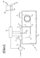
- the apparatus 1 comprises substantially an oven 2, an injector 3 (preferably of the "on-column” type) to inject the sample to be analyzed, a valve 4 to allow the evacuation of the solvent in the vapour phase (SVE valve), a detector 5 connected to the outlet of the capillary analytical column 6, lodged in the oven 2.
- a supply line 7 for the carrier gas To the injector 3 is connected a supply line 7 for the carrier gas; on the said supply line a valve 8 is arranged, said valve being operated electronically to regulate the flow rate and the pressure of the carrier gas to the apparatus 1.
- a pre-column 9 connected downstream of the injector 3 and upstream of the capillary analytical column 6. Between the pre-column tube 9 and the analytical capillary column 6 there is a "T" junction 10 from which a tube 11 departs that connects the capillary ducts 6 and 9 to the valve 4. Inside the oven 2 there are means 12 of regulation of the temperature in the same oven.
- the device according to the invention provides for a control unit 13 to generate the necessary control signals for the valve 8 on the carrier gas supply line, the means 12 of regulating the temperature, the injector 3 and the evacuation valve 4 of the solvent.
- the control unit 13 is in turn connected to a computer 14 from which it receives the inserted and/or calculated data for each phase of analysis.
- the computer 14 may be of any commonly known type, comprising at least a monitor 15, a hard-disk memory unit, a RAM memory, a keyboard 16 and a mouse 17 to select functions and/or insert data.
- the hard-disk of the computer 14 stores a plurality of reference values R evap corresponding to the evaporation rates of the solvent in relation to a corresponding plurality of discrete values of the variables P i , T j , V k and U s within respective pre-set intervals.
- the values of R evap(i,j,k,s) for a particular combination of carrier gas and solvent can be collected into a single matrix and memorized on the computer 14 as such.
- the reference values of the evaporation rates of the solvent are calculated only in terms of pre-set conditions i.e. for discrete representative values of the carrier gas pressure in the supply line 7, of the temperature inside the oven 2, of the initial volume of injected sample, and of the injection rate.
- the keyboard 16 and the mouse 17 allow the insertion or the selection of the data which characterize the actual analysis in all its phases.
- Also memorized in the computer are the data relating to the geometrical parameters of the capillary columns 6 and 9, e.g. length and internal diameter of the capillary column 6, data related to the volume of the injected sample, and date relating to the temperature inside the oven 2 and the pressure conditions of the carrier gas. All data are arranged in configurations which allows it to be moved easily between the hard-disk and the RAM.
- the computer 14 allows the effective value of the evaporation rate r evap of the solvent in use to be calculated in relation to data stored in the memory and/or inserted by the operator, and thus to calculate the parameters which characterize each phase of the gas chromatography analysis.
- Fig.2 shows a sequence comprising some of the steps the operator must go through on the computer 14 to set up an analysis correctly.
- some parameters are pre-inserted e.g. those related to the kind of carrier gas to be used and the type of retention gap 9 used in the gas chromatography apparatus.
- the reference values R evap are presumed to have been already calculated and memorized on the computer 14.
- a program which allows interaction between the operator and the computer 14 by means of a graphic interface.
- the selection of the data to be input in the steps of Fig.2 referred to above can be done either by the keyboard 16 or the mouse 17. It is important to state that the program run by the computer 14 has other functions which are not shown in fig.2; e.g. the memorization of a particular configuration on the hard disk; the retrieval of a particular configuration from the hard disk and recally it to the RAM; the sending of information related to a particular configuration to the control unit 13.
- Block 201 indicates the selection of the solvent used in the preparation of the sample to be analyzed.
- the selection of the solvent gives the computer 14 the information it needs to identify the matrix of reference values R evap to be used to calculate the actual values r evap related to the evaporation rate of the solvent.
- Block 202 indicates the inputting of the geometrical characteristics of the analytical capillary column, in particular the length and internal diameter, i.e. the data which influence the flow in the analytical column 6 after the solvent elimination phase.
- Blocks 211 and 212 indicate respectively the carrier gas pressure and the oven temperature at which the capillary conduit sections 6 and 9 in the oven 2 are maintained during the desolvation.
- the computer 14 proceeds to calculate the series of parameters particularly important indicated by the block 213. In particularly, it is made the calculation of the actual evaporation rate r evap of the solvent. Once r evap is known, the maximum injection volume V max , the volume of pre-column 9 with the valve 4 open and the volume of the conduit comprising the analytical column 6 and the pre-column 9 with the valve 4 closed, can all be determined.
- stage 22 information (block 221) relating to injected sample volume is requested, while at stage 23 information (block 231) relating to residual volume which remains in the pre-column 9 after the valve 4 has been closed and which will transfer to the analytical column 6 after the valve 4 has been closed, is requested.
- Block 232 contains the information relating to the sample injection rate and the time the valve 4 remains open after the end of the sample injection phase.
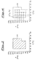
- Fig. 3 shows a Cartesian plane (T,P) containing the domain 215 from which the values of P and T can be selected at stage 21 of fig.2.
- Fig.4 shows the same domain 215 of fig.3 in which the reference values R evap calculated corresponding to the discrete value pairs (P i ,T j ) are indicated by (x).
- the point A(T A ,P A ) is any point within the domain 215 for which there is no a priori reference value R evap ; i.e. a pair of values T A and P A which represent the conditions of temperature and pressure imposed by the operator in stage 21 of fig. 2.
- the calculation of the actual value of the evaporation rate of the solvent r evap is by interpolation to the geometrically nearest reference value R evap to the point A i.e. the R evap for which the expression (P A -P i ) 2 + (T A -T j ) 2 is minimum.
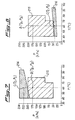
- Fig. 5 shows an example of a Cartesian plane (T,P) which is displayed on the monitor 15 of the computer 14 during selection of the temperature and pressure by the operator, during the initial selection of such values.
- the hatched area 215 in fig.5 shows the domain 215 already indicated in figs. 3 and 4, while the shaded area 216 shows the domain of the values of temperature and pressure which would give optimum flow conditions in the capillary column 6 after the valve 4 is closed.
- the point D (T D , P D ) could be in any position inside the area 215 but is not limited in any way to any position in area 216. So, if point D is inside the intersection of the areas 215 and 216 (as is shown in fig.5), then conditions can be chosen which are valid both for the sample injection and solvent removal phase, and for the transfer of the residual sample fraction from the pre-column 9 to the analytical capillary column 6. If point D is inside the area 215 but not inside area 216, then the flow rate through the column 6 will not be optimum for the analytical capillary column size after the valve 4 is closed.
- an initial point B (T B ,P B ) can be selected which defines the temperature and pressure conditions during injection of the sample and removewal of the solvent, and a second point C (T C , P C ) which defines the temperature and pressure conditions after the valve 4 is closed.
- Point B may be anywhere within the area 215 and point C may be anywhere within the area 216.
- an initial criterium for optimization might be maximum volume injectable in the pre-column 9. It is known that - all other things (e.g. temperature and pre-column type) being equal - the volume of sample which can ber injected on the pre-column increases with increasing carrier gas pressure. However, a high carrier gas pressure may not be ideal in the capillary analytical column after the SVE is closed. So, it is particularly advantageous to be able to set one pressure P B to give large volume sample injection and then a second pressure P C which gives optimum analytical column flow performance.
- the program run by the computer 14 facilitates the selection of such optimization which may be selected at stage 21 of fig.2.
- a diagram similar to that of fig.5 is shown on the monitor 15 when the operator must select temperature and pressure, on which the point D represents the predefined values of temperature T D and pressure P D , e.g the default values calculated by the program and/or memorized by the computer 14. The operator may keep those values or adjust the temperature and/or pressure while keeping the point D within the area 215.
- the pressure PB is always greater than the pressure PC while the temperature TB and TC are kept constant at the same value TD which was calculated or set before the optimization.
- a further criterion of optimization of the method according to the present invention is the imposition of a pre-set solvent flow-rate through the valve 4.
- This option (which is particularly practical for operators in the field) allows the automatic calculation of conditions which give optimum flow rate in the analytical capillary column after the valve 4 is closed, while the solvent flow-rate through the said valve 4 in the prior phase is set by the operator.
- the practice is widespread of estimating approximately both the length of time the valve SVE is open and the quantity of solvent removed through it on the basis of the flow-rate through the same valve.
- the program provides for the manual adjustment of certain parameters, among which are the sample injection flow-rate, the opening time of the value 4, at least the carrier gas pressure during the sample injection and solvent removal phases, together with a temperature value different to that previously set or calculated by the program.
Landscapes
- Physics & Mathematics (AREA)
- Health & Medical Sciences (AREA)
- Life Sciences & Earth Sciences (AREA)
- Chemical & Material Sciences (AREA)
- Analytical Chemistry (AREA)
- Biochemistry (AREA)
- General Health & Medical Sciences (AREA)
- General Physics & Mathematics (AREA)
- Immunology (AREA)
- Pathology (AREA)
- Sampling And Sample Adjustment (AREA)
- Treatment Of Liquids With Adsorbents In General (AREA)
Claims (18)
- Dispositif pour la séparation en ses composants individuels d'un échantillon qui est injecté dans un flux de gaz porteur dans le tube capillaire d'un appareil (1) d'analyse de chromatographie en phase gazeuse, dans lequel l'échantillon consiste en une solution d'un ou plusieurs composants devant être analysés dissous dans un solvant, le dispositif comprenant :des moyens permettant de calculer, de recueillir en matrice et de mémoriser préalablement une pluralité de valeurs de référence Révap correspondant à la vitesse d'évaporation dudit solvant, combiné audit gaz porteur, lesdites valeurs de référence Révap correspondant à une pluralité de valeurs discrètes entre des intervalles pré-définis respectifs, lesdites valeurs discrètes étant représentatives des conditions spécifiques de pression du gaz porteur dans ledit tube capillaire, des températures spécifiques auxquelles ledit tube capillaire est soumis, des volumes initiaux pré-définis de l'échantillon injectés dans ledit tube capillaire et du débit d'injection pré-défini dudit échantillon ;des moyens permettant de calculer, en utilisant la matrice mémorisée des valeurs de référence Révap identifiées pour ledit solvant, et de mémoriser la valeur révap réelle pour la vitesse d'évaporation du solvant correspondant aux pressions réelles du gaz porteur dans ledit tube capillaire, aux températures spécifiques auxquelles ledit tube capillaire est soumis, pour les volumes initiaux réels injectés d'échantillon et pour le débit réel d'injection (232) ; etdes moyens permettant de générer un ou plusieurs signaux (13) de commande pour l'appareil (1) de chromatographie en phase gazeuse afin de déterminer la fraction volumétrique de l'échantillon transféré (231) à travers le tube capillaire par rapport à ses caractéristiques et à ses dimensions (202), géométriques.
- Dispositif selon la revendication 1, caractérisé en ce que les moyens permettant de calculer et de mémoriser les valeurs Révap et révap pour la vitesse d'évaporation du solvant comprennent de préférence au moins un ordinateur (14).
- Dispositif selon la revendication 1 ou 2, caractérisé en ce que ledit moyen permettant de générer lesdits signaux de commande comprend une unité (13) de commande qui est connectée audit ordinateur (14) et audit appareil (1) de chromatographie en phase gazeuse.
- Dispositif selon l'une quelconque des revendications précédentes, caractérisé en ce que ledit tube capillaire comprend une pré-colonne (9) dudit appareil de chromatographie en phase gazeuse (1).
- Dispositif selon l'une quelconque des revendications précédentes, caractérisé en ce que ledit tube capillaire comprend une colonne (6) capillaire analytique dudit appareil de chromatographie en phase gazeuse (1).
- Dispositif selon l'une quelconque des revendications précédentes, caractérisé en ce que ledit appareil de chromatographie en phase gazeuse (1) comprend une colonne (6) capillaire analytique logée dans un four (2), un injecteur (3) monté en amont de ladite colonne (6) capillaire analytique, une conduite d'alimentation pour le gaz porteur (7) connectée audit injecteur (3), une pré-colonne (9) logée dans ledit four (2) entre ledit injecteur et la colonne capillaire analytique, un moyen à soupape (4) montée en aval de la pré-colonne (9) et en amont de la colonne (6) capillaire analytique destiné à l'élimination de la vapeur de solvant provenant de l'appareil, un moyen de régulation de la température (12) dudit four (2), et un moyen de régulation de la pression (8) dudit gaz porteur.
- Dispositif selon l'une quelconque des revendications précédentes, caractérisé en ce que ladite unité (13) de commande comprend un moyen permettant de générer au moins un signal de commande pour ledit injecteur (3), au moins un signal de commande pour ledit moyen à soupape (4), au moins un signal de commande pour ledit moyen de régulation de la température (12) du four, au moins un signal de commande pour ledit moyen de régulation de la pression (8) dudit gaz porteur dans ledit tube capillaire.
- Procédé destiné à la séparation en ses composants individuels d'un échantillon qui est injecté dans un flux de gaz porteur dans le tube capillaire d'un appareil (1) de chromatographie en phase gazeuse, ledit échantillon consistant en une solution d'un ou de plusieurs composants devant être analysés, dissous dans un solvant, le procédé comprenant :le calcul, la collecte en matrice et la mémorisation préalables d'une pluralité de valeurs de référence Révap correspondant aux vitesses d'évaporation dudit solvant, combiné audit gaz porteur utilisé, lesdites valeurs de référence Révap correspondant à une pluralité de valeurs discrètes à des intervalles pré-définis respectifs, lesdites valeurs discrètes étant représentatives des conditions spécifiques de pression du gaz porteur dans ledit tube capillaire, des températures spécifiques auxquelles ledit tube capillaire est soumis, des volumes initiaux pré-définis de l'échantillon injecté dans ledit tube capillaire et des débits d'injection pré-définis de l'échantillon ;le calcul en utilisant la matrice mémorisée des valeurs de référence Révap identifiées pour ledit solvant, et la mémorisation de la valeur révap réelle pour les vitesses d'évaporation des solvants (201) correspondant aux pressions (210) réelles du gaz porteur dans le tube capillaire, aux températures (212) réelles auxquelles est soumis ledit tube capillaire, aux volumes initiaux réels d'échantillon injecté et aux débits (232) réels d'injection dudit échantillon ;la génération d'un ou de plusieurs signaux de commande pour l'appareil (1) de chromatographie en phase gazeuse afin de déterminer la fraction volumétrique de l'échantillon transféré à travers le tube capillaire par rapport à ses caractéristiques et à ses dimensions géométriques.
- Procédé selon la revendication 8, caractérisé en ce que la vitesse réelle d'évaporation révap est calculée par interpolation vers les valeurs de référence Révap géométriquement les plus proches dans un ensemble de valeurs représentatives des conditions réelles de pression du gaz porteur dans ledit tube capillaire, des températures réelles auxquelles le tube capillaire est soumis, du volume réel d'échantillon initialement injecté et du débit réel d'injection dudit échantillon.
- Procédé selon la revendication 8 ou 9, caractérisé en ce que ledit tube capillaire comprend une pré-colonne (9) et une colonne (6) capillaire analytique dudit appareil de chromatographie en phase gazeuse, et comprend un moyen à soupape (4) monté en aval de la pré-colonne (9) et en amont de la colonne (6) capillaire analytique destiné à l'élimination de la vapeur de solvant évaporée à partir dudit échantillon.
- Procédé selon la revendication 10, caractérisé en ce que le calcul du volume maximum d'échantillon qui peut être injecté sur ladite pré-colonne est fourni.
- Procédé selon la revendication 10, caractérisé en ce qu'il est fourni le calcul de la fraction volumétrique de l'échantillon éliminée par évaporation à travers le moyen à soupape (4) par rapport à la quantité d'échantillon qui est transférée sur la colonne (6) capillaire analytique dudit appareil (1) de chromatographie en phase gazeuse.
- Procédé selon la revendication 10, caractérisé en ce qu'il est fourni le calcul d'un intervalle de temps correspondant à la durée de la phase d'élimination du solvant pendant la période dans laquelle le moyen à soupape reste ouvert, le commencement de ladite période d'ouverture coïncidant avec l'achèvement de la phase d'injection de l'échantillon sur ladite pré-colonne (9).
- Procédé selon la revendication 10, caractérisé en ce que ladite phase d'injection de l'échantillon sur ladite pré-colonne (9) et ladite phase d'élimination du solvant à travers le moyen à soupape (4) sont réalisés tout en maintenant ladite pré-colonne (9) à la même température et le gaz porteur à la même pression.
- Procédé selon l'une quelconque des revendications 8 à 14, caractérisé en ce qu'il est fourni le calcul d'une valeur initiale correspondant aux conditions de pression du gaz porteur dans ledit tube capillaire pour une température spécifique pendant la phase d'injection de l'échantillon dans la pré-colonne (9) et pendant l'élimination du solvant évaporé à travers ledit moyen à soupape (4) ; ladite valeur initiale de pression étant calculée afin de faire en sorte que le volume maximum d'échantillon soit injecté sur ladite pré-colonne.
- Procédé selon l'une quelconque des revendications 8 à 14, caractérisé en ce qu'il est fourni le calcul d'une valeur initiale correspondant aux conditions de pression du gaz porteur dans ledit tube capillaire pour une température spécifique pendant la phase d'injection de l'échantillon sur la pré-colonne (9) et pendant l'élimination du solvant évaporé à travers ledit moyen à soupape (4), ladite valeur initiale étant calculée afin d'assurer un débit pré-défini à travers ledit moyen à soupape par rapport aux caractéristiques et aux dimensions géométriques de ladite pré-colonne.
- Procédé selon l'une quelconque des revendications 8 à 16, caractérisé en ce qu'il est fourni le calcul d'une seconde valeur correspondant aux conditions de pression du gaz porteur dans ladite pré-colonne (9) et dans ladite colonne (6) capillaire analytique après la fermeture dudit moyen à soupape (4), ladite seconde valeur étant calculée afin d'assurer un débit pré-défini à travers la colonne (6) capillaire analytique par rapport à ses caractéristiques et à ses dimensions géométriques.
- Procédé selon l'une quelconque des revendications 15 à 17, caractérisé en ce que la température à laquelle la pression initiale est calculée est identique à la température à laquelle la seconde valeur de pression est calculée.
Applications Claiming Priority (2)
| Application Number | Priority Date | Filing Date | Title |
|---|---|---|---|
| ITMI952785 | 1995-12-29 | ||
| IT95MI002785A IT1277749B1 (it) | 1995-12-29 | 1995-12-29 | Dispositivo e metodo per effettuare la separazione di un campione in singoli componenti in un condotto capillare di un apparecchio per la |
Publications (3)
| Publication Number | Publication Date |
|---|---|
| EP0783103A2 EP0783103A2 (fr) | 1997-07-09 |
| EP0783103A3 EP0783103A3 (fr) | 1999-05-12 |
| EP0783103B1 true EP0783103B1 (fr) | 2005-08-03 |
Family
ID=11372837
Family Applications (1)
| Application Number | Title | Priority Date | Filing Date |
|---|---|---|---|
| EP96120144A Expired - Lifetime EP0783103B1 (fr) | 1995-12-29 | 1996-12-16 | Dispositif et procédé de séparation d'un échantillon dans ses composants individuels dans un conduit capillaire d'un appareil d'analyse chromatographique en phase gazeuse |
Country Status (4)
| Country | Link |
|---|---|
| US (1) | US5738707A (fr) |
| EP (1) | EP0783103B1 (fr) |
| DE (1) | DE69635013T2 (fr) |
| IT (1) | IT1277749B1 (fr) |
Families Citing this family (7)
| Publication number | Priority date | Publication date | Assignee | Title |
|---|---|---|---|---|
| IT1292452B1 (it) | 1997-07-02 | 1999-02-08 | Thermoquest Italia Spa | Metodo,dispositivo e apparecchio per rilevare cambiamenti di stato in un capillare e ottimizzare le condizioni di iniezione di un campione |
| ITMI981142A1 (it) * | 1998-05-22 | 1999-11-22 | Thermoquest Italia Spa | Metodo e apparecchio per l'introduzione di campioni di volume elevato in colonne capillari per gascromatografia |
| US6036747A (en) * | 1998-07-24 | 2000-03-14 | Hewlett-Packard Company | Column specific parameters for retention time locking in chromatography |
| DE10049079A1 (de) * | 2000-10-02 | 2002-04-18 | Merck Patent Gmbh | Verfahren und System zur Methodenoptimierung in der Chromatographie |
| DE10128546A1 (de) * | 2001-06-13 | 2002-12-19 | Merck Patent Gmbh | Verfahren und Vorrichtung zur automatischen, optimierten Durchführung chromatographischer Analysen |
| ATE555186T1 (de) * | 2001-06-15 | 2012-05-15 | Shell Int Research | Ein mikrokristallines wachs |
| JP4699520B2 (ja) * | 2005-06-14 | 2011-06-15 | パーキンエルマー・ヘルス・サイエンシズ・インコーポレーテッド | クロマトグラフカラムを冷却する方法 |
Family Cites Families (17)
| Publication number | Priority date | Publication date | Assignee | Title |
|---|---|---|---|---|
| US3881892A (en) * | 1972-04-28 | 1975-05-06 | Charles W Gehrke | Chromatograph system and method |
| JPS63131059A (ja) * | 1986-11-19 | 1988-06-03 | Yokogawa Electric Corp | ガスクロマトグラフ |
| US4805441A (en) * | 1988-02-22 | 1989-02-21 | Cms Research Corporation | Continuous air monitoring apparatus and method |
| IT1226748B (it) * | 1988-08-22 | 1991-02-05 | Erba Strumentazione | Metodo e dispositivo per il controllo di funzioni in un gascromatografo. |
| US4994096A (en) * | 1989-05-09 | 1991-02-19 | Hewlett-Packard Co. | Gas chromatograph having integrated pressure programmer |
| US4948389A (en) * | 1989-05-22 | 1990-08-14 | Hewlett-Packard Company | Gas chromatograph having cyro blast coolings |
| US5083450A (en) * | 1990-05-18 | 1992-01-28 | Martin Marietta Energy Systems, Inc. | Gas chromatograph-mass spectrometer (gc/ms) system for quantitative analysis of reactive chemical compounds |
| US5096471A (en) * | 1990-09-28 | 1992-03-17 | The Regents Of The University Of Michigan | Gas chromatography system and methods |
| US5108466A (en) * | 1990-12-21 | 1992-04-28 | Hewlett-Packard Company | Apparatus and methods for controlling fluids provided to a chromatographic detector |
| US5305232A (en) * | 1992-05-13 | 1994-04-19 | The University Of Rochester | Chromatography system |
| DE69323645T2 (de) * | 1992-05-18 | 1999-09-09 | Hewlett-Packard Co. | Verfahren zur Berechnung der Betriebsparameter eines Gaschromatografens |
| US5476000A (en) * | 1994-03-31 | 1995-12-19 | Hewlett-Packard Company | Retention time stability in a gas chromatographic apparatus |
| US5431712A (en) * | 1994-05-31 | 1995-07-11 | Hewlett-Packard Company | Reconfigurable pneumatic control for split/splitless injection |
| US5467635A (en) * | 1994-12-12 | 1995-11-21 | Shimadzu Corporation | Gas chromatograph |
| US5524084A (en) * | 1994-12-30 | 1996-06-04 | Hewlett-Packard Company | Method and apparatus for improved flow and pressure measurement and control |
| US5567227A (en) * | 1995-01-23 | 1996-10-22 | Hewlett-Packard Company | Method for improving the range of stable control of the pneumatic system of a gas chromatograph |
| US5545252A (en) * | 1995-03-01 | 1996-08-13 | The Perkin-Elmer Corporation | Flow regulation in gas chromatograph |
-
1995
- 1995-12-29 IT IT95MI002785A patent/IT1277749B1/it active IP Right Grant
-
1996
- 1996-12-12 US US08/766,397 patent/US5738707A/en not_active Expired - Lifetime
- 1996-12-16 EP EP96120144A patent/EP0783103B1/fr not_active Expired - Lifetime
- 1996-12-16 DE DE69635013T patent/DE69635013T2/de not_active Expired - Lifetime
Also Published As
| Publication number | Publication date |
|---|---|
| IT1277749B1 (it) | 1997-11-12 |
| EP0783103A2 (fr) | 1997-07-09 |
| ITMI952785A0 (fr) | 1995-12-29 |
| DE69635013D1 (de) | 2005-09-08 |
| DE69635013T2 (de) | 2006-06-01 |
| EP0783103A3 (fr) | 1999-05-12 |
| US5738707A (en) | 1998-04-14 |
| ITMI952785A1 (it) | 1997-06-29 |
Similar Documents
| Publication | Publication Date | Title |
|---|---|---|
| US4883504A (en) | Gas chromatograph | |
| EP0355546B1 (fr) | Appareil et procédé de contrÔle des fonctions d'un chromatographe à gaz | |
| EP0570707B1 (fr) | Procédé de calcul des paramètres de fonctionnement d'un chromatographe à gaz | |
| US5196039A (en) | Apparatus and method of multi-dimensional chemical separation | |
| EP0783103B1 (fr) | Dispositif et procédé de séparation d'un échantillon dans ses composants individuels dans un conduit capillaire d'un appareil d'analyse chromatographique en phase gazeuse | |
| US8716025B2 (en) | Drifting two-dimensional separation with adaption of second dimension gradient to actual first dimension condition | |
| US20020194898A1 (en) | Retention-time locked comprehensive multidimensional gas chromatography | |
| CN102879508B (zh) | 用于液相色谱仪的控制设备 | |
| US20140157878A1 (en) | System and program for controlling liquid chromatograph | |
| EP0829717B1 (fr) | Système de courant inverse pour chromatographie en phase gazeuse | |
| US5759234A (en) | Method and device for the injection of liquid samples in a gas chromatograph | |
| EP1993705B1 (fr) | Modulateur de commutation à deux valves pour chromatographie en phase gazeuse bidimensionnelle globale | |
| US4038053A (en) | Method and apparatus for introducing liquid samples into a gas chromatographic column | |
| US4442217A (en) | Sample injection | |
| EP2256490A1 (fr) | Contrôle de la pression gazeuse pour la chromatographie gazeuse | |
| JP6575384B2 (ja) | 液体クロマトグラフ装置 | |
| JP5081825B2 (ja) | 定量データ分析を可能にするために包括的2(多)次元クロマトグラフィー(分離)システムにおいてデータ取り込みおよびモジュレーションを同期させるシステムおよび方法 | |
| CA1078215A (fr) | Dilution d'un echantillon liquide pour analyse chromatographique | |
| EP3849682B1 (fr) | Système et procédé de division commandée par pression d'un échantillon chimique | |
| JP5076807B2 (ja) | マルチディメンジョナルガスクロマトグラフ装置 | |
| Snow | Inlet systems for gas chromatography | |
| JP2004309252A (ja) | クロマトグラフ用データ処理装置 | |
| JP2014153075A (ja) | ガス流路切替装置、ガス流路切替方法及びガス流路切替プログラム | |
| JPH1026616A (ja) | クロマトグラフ分析システム | |
| JPH11352120A (ja) | 高分子物質の分析装置 |
Legal Events
| Date | Code | Title | Description |
|---|---|---|---|
| PUAI | Public reference made under article 153(3) epc to a published international application that has entered the european phase |
Free format text: ORIGINAL CODE: 0009012 |
|
| AK | Designated contracting states |
Kind code of ref document: A2 Designated state(s): DE |
|
| PUAL | Search report despatched |
Free format text: ORIGINAL CODE: 0009013 |
|
| AK | Designated contracting states |
Kind code of ref document: A3 Designated state(s): DE |
|
| 17P | Request for examination filed |
Effective date: 19990721 |
|
| RAP1 | Party data changed (applicant data changed or rights of an application transferred) |
Owner name: THERMO FINNIGAN ITALIA S.P.A. |
|
| 17Q | First examination report despatched |
Effective date: 20031021 |
|
| GRAP | Despatch of communication of intention to grant a patent |
Free format text: ORIGINAL CODE: EPIDOSNIGR1 |
|
| GRAS | Grant fee paid |
Free format text: ORIGINAL CODE: EPIDOSNIGR3 |
|
| GRAA | (expected) grant |
Free format text: ORIGINAL CODE: 0009210 |
|
| RAP1 | Party data changed (applicant data changed or rights of an application transferred) |
Owner name: THERMO ELECTRON S.P.A. |
|
| AK | Designated contracting states |
Kind code of ref document: B1 Designated state(s): DE |
|
| REF | Corresponds to: |
Ref document number: 69635013 Country of ref document: DE Date of ref document: 20050908 Kind code of ref document: P |
|
| PLBE | No opposition filed within time limit |
Free format text: ORIGINAL CODE: 0009261 |
|
| STAA | Information on the status of an ep patent application or granted ep patent |
Free format text: STATUS: NO OPPOSITION FILED WITHIN TIME LIMIT |
|
| 26N | No opposition filed |
Effective date: 20060504 |
|
| REG | Reference to a national code |
Ref country code: DE Ref legal event code: R082 Ref document number: 69635013 Country of ref document: DE Representative=s name: GODEMEYER BLUM LENZE PATENTANWAELTE, PARTNERSC, DE Ref country code: DE Ref legal event code: R082 Ref document number: 69635013 Country of ref document: DE Representative=s name: GODEMEYER BLUM LENZE - WERKPATENT, DE Ref country code: DE Ref legal event code: R082 Ref document number: 69635013 Country of ref document: DE Representative=s name: GODEMEYER BLUM LENZE PARTNERSCHAFT, PATENTANWA, DE |
|
| PGFP | Annual fee paid to national office [announced via postgrant information from national office to epo] |
Ref country code: DE Payment date: 20141211 Year of fee payment: 19 |
|
| REG | Reference to a national code |
Ref country code: DE Ref legal event code: R119 Ref document number: 69635013 Country of ref document: DE |
|
| PG25 | Lapsed in a contracting state [announced via postgrant information from national office to epo] |
Ref country code: DE Free format text: LAPSE BECAUSE OF NON-PAYMENT OF DUE FEES Effective date: 20160701 |