EP0783106A1 - Poursuite d'un mouvement à l'aide des gradients thermiques appliqués - Google Patents
Poursuite d'un mouvement à l'aide des gradients thermiques appliqués Download PDFInfo
- Publication number
- EP0783106A1 EP0783106A1 EP96309523A EP96309523A EP0783106A1 EP 0783106 A1 EP0783106 A1 EP 0783106A1 EP 96309523 A EP96309523 A EP 96309523A EP 96309523 A EP96309523 A EP 96309523A EP 0783106 A1 EP0783106 A1 EP 0783106A1
- Authority
- EP
- European Patent Office
- Prior art keywords
- thermal
- unit
- temperature
- paper
- localized
- Prior art date
- Legal status (The legal status is an assumption and is not a legal conclusion. Google has not performed a legal analysis and makes no representation as to the accuracy of the status listed.)
- Granted
Links
- 230000001939 inductive effect Effects 0.000 claims abstract description 6
- 238000004364 calculation method Methods 0.000 claims description 7
- 230000004044 response Effects 0.000 claims description 6
- 230000001427 coherent effect Effects 0.000 claims description 5
- 239000002826 coolant Substances 0.000 claims 3
- 238000009529 body temperature measurement Methods 0.000 claims 1
- 230000003028 elevating effect Effects 0.000 claims 1
- 239000000463 material Substances 0.000 description 19
- 238000012545 processing Methods 0.000 description 14
- 238000010438 heat treatment Methods 0.000 description 9
- 238000000034 method Methods 0.000 description 9
- XUIMIQQOPSSXEZ-UHFFFAOYSA-N Silicon Chemical compound [Si] XUIMIQQOPSSXEZ-UHFFFAOYSA-N 0.000 description 5
- 238000004458 analytical method Methods 0.000 description 5
- 238000003491 array Methods 0.000 description 5
- 238000005259 measurement Methods 0.000 description 5
- 230000007246 mechanism Effects 0.000 description 5
- 239000000523 sample Substances 0.000 description 5
- 229910052710 silicon Inorganic materials 0.000 description 5
- 239000010703 silicon Substances 0.000 description 5
- 230000002123 temporal effect Effects 0.000 description 5
- 238000001514 detection method Methods 0.000 description 4
- 239000000976 ink Substances 0.000 description 4
- 230000003287 optical effect Effects 0.000 description 4
- 230000000737 periodic effect Effects 0.000 description 4
- 230000008569 process Effects 0.000 description 4
- 239000000919 ceramic Substances 0.000 description 3
- 238000011109 contamination Methods 0.000 description 3
- 238000001816 cooling Methods 0.000 description 3
- 230000006378 damage Effects 0.000 description 3
- 235000012431 wafers Nutrition 0.000 description 3
- -1 wires Substances 0.000 description 3
- 230000008901 benefit Effects 0.000 description 2
- 239000000975 dye Substances 0.000 description 2
- 238000005516 engineering process Methods 0.000 description 2
- 239000003000 extruded plastic Substances 0.000 description 2
- 238000005188 flotation Methods 0.000 description 2
- 239000012530 fluid Substances 0.000 description 2
- 239000011888 foil Substances 0.000 description 2
- 230000001965 increasing effect Effects 0.000 description 2
- 238000007689 inspection Methods 0.000 description 2
- 238000002955 isolation Methods 0.000 description 2
- 238000003913 materials processing Methods 0.000 description 2
- 229910052751 metal Inorganic materials 0.000 description 2
- 239000002184 metal Substances 0.000 description 2
- 150000002739 metals Chemical class 0.000 description 2
- 239000013307 optical fiber Substances 0.000 description 2
- 239000004033 plastic Substances 0.000 description 2
- 229920003023 plastic Polymers 0.000 description 2
- 230000005855 radiation Effects 0.000 description 2
- 239000004065 semiconductor Substances 0.000 description 2
- 239000000758 substrate Substances 0.000 description 2
- 230000005679 Peltier effect Effects 0.000 description 1
- 229910052581 Si3N4 Inorganic materials 0.000 description 1
- VYPSYNLAJGMNEJ-UHFFFAOYSA-N Silicium dioxide Chemical compound O=[Si]=O VYPSYNLAJGMNEJ-UHFFFAOYSA-N 0.000 description 1
- 229910000831 Steel Inorganic materials 0.000 description 1
- 230000004075 alteration Effects 0.000 description 1
- 229910052782 aluminium Inorganic materials 0.000 description 1
- XAGFODPZIPBFFR-UHFFFAOYSA-N aluminium Chemical compound [Al] XAGFODPZIPBFFR-UHFFFAOYSA-N 0.000 description 1
- 238000003486 chemical etching Methods 0.000 description 1
- 238000010276 construction Methods 0.000 description 1
- 238000012937 correction Methods 0.000 description 1
- 230000003247 decreasing effect Effects 0.000 description 1
- 230000008021 deposition Effects 0.000 description 1
- 238000003708 edge detection Methods 0.000 description 1
- 238000000609 electron-beam lithography Methods 0.000 description 1
- 238000003384 imaging method Methods 0.000 description 1
- 230000003116 impacting effect Effects 0.000 description 1
- 230000006698 induction Effects 0.000 description 1
- 230000001788 irregular Effects 0.000 description 1
- 238000004093 laser heating Methods 0.000 description 1
- 239000007788 liquid Substances 0.000 description 1
- 238000004519 manufacturing process Methods 0.000 description 1
- 239000003550 marker Substances 0.000 description 1
- 238000012986 modification Methods 0.000 description 1
- 230000004048 modification Effects 0.000 description 1
- 239000000123 paper Substances 0.000 description 1
- 238000005192 partition Methods 0.000 description 1
- 238000000206 photolithography Methods 0.000 description 1
- 229910021420 polycrystalline silicon Inorganic materials 0.000 description 1
- 229920005591 polysilicon Polymers 0.000 description 1
- HQVNEWCFYHHQES-UHFFFAOYSA-N silicon nitride Chemical compound N12[Si]34N5[Si]62N3[Si]51N64 HQVNEWCFYHHQES-UHFFFAOYSA-N 0.000 description 1
- 229910052814 silicon oxide Inorganic materials 0.000 description 1
- 239000002356 single layer Substances 0.000 description 1
- 239000007787 solid Substances 0.000 description 1
- 239000010959 steel Substances 0.000 description 1
- 230000003685 thermal hair damage Effects 0.000 description 1
- 238000012876 topography Methods 0.000 description 1
- 238000012546 transfer Methods 0.000 description 1
- 230000001052 transient effect Effects 0.000 description 1
- 239000002023 wood Substances 0.000 description 1
Images


Classifications
-
- B—PERFORMING OPERATIONS; TRANSPORTING
- B65—CONVEYING; PACKING; STORING; HANDLING THIN OR FILAMENTARY MATERIAL
- B65H—HANDLING THIN OR FILAMENTARY MATERIAL, e.g. SHEETS, WEBS, CABLES
- B65H7/00—Controlling article feeding, separating, pile-advancing, or associated apparatus, to take account of incorrect feeding, absence of articles, or presence of faulty articles
- B65H7/02—Controlling article feeding, separating, pile-advancing, or associated apparatus, to take account of incorrect feeding, absence of articles, or presence of faulty articles by feelers or detectors
-
- B—PERFORMING OPERATIONS; TRANSPORTING
- B65—CONVEYING; PACKING; STORING; HANDLING THIN OR FILAMENTARY MATERIAL
- B65H—HANDLING THIN OR FILAMENTARY MATERIAL, e.g. SHEETS, WEBS, CABLES
- B65H23/00—Registering, tensioning, smoothing or guiding webs
- B65H23/02—Registering, tensioning, smoothing or guiding webs transversely
- B65H23/0204—Sensing transverse register of web
-
- B—PERFORMING OPERATIONS; TRANSPORTING
- B65—CONVEYING; PACKING; STORING; HANDLING THIN OR FILAMENTARY MATERIAL
- B65H—HANDLING THIN OR FILAMENTARY MATERIAL, e.g. SHEETS, WEBS, CABLES
- B65H23/00—Registering, tensioning, smoothing or guiding webs
- B65H23/04—Registering, tensioning, smoothing or guiding webs longitudinally
- B65H23/046—Sensing longitudinal register of web
-
- B—PERFORMING OPERATIONS; TRANSPORTING
- B65—CONVEYING; PACKING; STORING; HANDLING THIN OR FILAMENTARY MATERIAL
- B65H—HANDLING THIN OR FILAMENTARY MATERIAL, e.g. SHEETS, WEBS, CABLES
- B65H5/00—Feeding articles separated from piles; Feeding articles to machines
- B65H5/22—Feeding articles separated from piles; Feeding articles to machines by air-blast or suction device
- B65H5/228—Feeding articles separated from piles; Feeding articles to machines by air-blast or suction device by air-blast devices
-
- G—PHYSICS
- G01—MEASURING; TESTING
- G01P—MEASURING LINEAR OR ANGULAR SPEED, ACCELERATION, DECELERATION, OR SHOCK; INDICATING PRESENCE, ABSENCE, OR DIRECTION, OF MOVEMENT
- G01P3/00—Measuring linear or angular speed; Measuring differences of linear or angular speeds
- G01P3/64—Devices characterised by the determination of the time taken to traverse a fixed distance
- G01P3/68—Devices characterised by the determination of the time taken to traverse a fixed distance using optical means, i.e. using infrared, visible, or ultraviolet light
-
- B—PERFORMING OPERATIONS; TRANSPORTING
- B65—CONVEYING; PACKING; STORING; HANDLING THIN OR FILAMENTARY MATERIAL
- B65H—HANDLING THIN OR FILAMENTARY MATERIAL, e.g. SHEETS, WEBS, CABLES
- B65H2511/00—Dimensions; Position; Numbers; Identification; Occurrences
- B65H2511/50—Occurence
- B65H2511/51—Presence
- B65H2511/512—Marks, e.g. invisible to the human eye; Patterns
-
- B—PERFORMING OPERATIONS; TRANSPORTING
- B65—CONVEYING; PACKING; STORING; HANDLING THIN OR FILAMENTARY MATERIAL
- B65H—HANDLING THIN OR FILAMENTARY MATERIAL, e.g. SHEETS, WEBS, CABLES
- B65H2513/00—Dynamic entities; Timing aspects
- B65H2513/40—Movement
-
- B—PERFORMING OPERATIONS; TRANSPORTING
- B65—CONVEYING; PACKING; STORING; HANDLING THIN OR FILAMENTARY MATERIAL
- B65H—HANDLING THIN OR FILAMENTARY MATERIAL, e.g. SHEETS, WEBS, CABLES
- B65H2515/00—Physical entities not provided for in groups B65H2511/00 or B65H2513/00
- B65H2515/40—Temperature; Thermal conductivity
-
- B—PERFORMING OPERATIONS; TRANSPORTING
- B65—CONVEYING; PACKING; STORING; HANDLING THIN OR FILAMENTARY MATERIAL
- B65H—HANDLING THIN OR FILAMENTARY MATERIAL, e.g. SHEETS, WEBS, CABLES
- B65H2553/00—Sensing or detecting means
- B65H2553/20—Sensing or detecting means using electric elements
- B65H2553/27—Electro mechanical thermal sensors, e.g. thermocouples, pyroelectric sensors, temperature sensitive sensor
-
- B—PERFORMING OPERATIONS; TRANSPORTING
- B65—CONVEYING; PACKING; STORING; HANDLING THIN OR FILAMENTARY MATERIAL
- B65H—HANDLING THIN OR FILAMENTARY MATERIAL, e.g. SHEETS, WEBS, CABLES
- B65H2557/00—Means for control not provided for in groups B65H2551/00 - B65H2555/00
- B65H2557/50—Use of particular electromagnetic waves, e.g. light, radiowaves or microwaves
- B65H2557/51—Laser
Definitions
- a material processing system must often precisely control position and velocity of objects moving through the system.
- material processing systems control object movement by physically engaging the object with a separate object drive mechanism moving at a predetermined velocity along a predetermined path.
- gear driven ratchets, rollers, hooks, or conveyors are widely employed to move objects as diverse as paper, semiconductors, plastics, or steel by mechanically engaging the objects, and moving the engaged objects along a desired path at a fixed velocity.
- mechanical or frictional engagement of objects does have a disadvantage of requiring direct physical contact with an object. For certain applications, including processing of high purity or delicate materials, contamination or damage to the object may result from mechanical grasping or contact. This is particularly true for high speed processing systems, which may damage objects simply by engaging them.
- high speed rollers may damage paper through differential engagement of misaligned paper with the roller, resulting in ripping or tearing of the paper.
- the possibility of contaminating high purity silicon wafers moving along a processing line is greatly increased by the use of high speed mechanical arms or grippers.
- Object drive mechanisms based on fluid support, electrostatic, or electromagnetic systems have all been employed to move objects with requiring solid mechanical contact.
- electromagnetic flotation systems can be used to move ferroelectric materials without physically contacting a ferroelectric object.
- material processing systems that rely on some form of fluid support are used, with object entrainment in liquids, bubble flotation methods, support on a laminar air flows, or support by directed air jets all being used to lift and propel objects through a materials processing system.
- a separate position and velocity sensor system is required.
- This can be a mechanical sensor, such as a lightweight ball roller that is situated in revolving contact with a moving object, or a non-contacting sensor such as an object edge detecting laser or video tracking camera.
- available mechanical sensor systems are difficult to use on levitated objects, still increase the risk of contamination, and are often fragile and difficult to calibrate.
- even lightly contacting roller bearings, lever arms, or other mechanical devices can unfavorably alter the dynamic behavior of the object.
- mechanical sensors are often overly sensitive to changes in object topography and surface properties, making consistent measurements difficult.
- Optical position/velocity measurement systems do not have the limitations of mechanical systems, but do have their own distinct disadvantages.
- a laser emitter/light detector combination that measures object position as a function of light blockage as an object's edge passes between the laser and its corresponding light detector may greatly reduce the risk of contamination as compared to mechanical sensors, but can be expensive and require an inordinate number of separate sensor/detector pairs to track three dimensional movements.
- Video tracking camera systems are similarly expensive, and may require substantial image processing to detect object features and reliably determine position and velocity.
- the present invention provides an object tracking and motion control system that includes a thermal marking unit for inducing localized thermal indicia on objects, an adjacent thermal tracking unit for measuring movement of objects marked with localized thermal indicia, and a motion control unit connected to the thermal tracking unit for adjusting motion of objects marked with induced localized thermal indicia based on their measured movement.
- the system preferably, further comprises a thermal marking unit for inducing localized thermal gradients on the object.
- the invention further provides a paper handling system according to claim 10 of the appended claims.
- An advantage of the present invention that it does not require physically contacting or permanently marking the tracked object. Furthermore, the present invention does not rely on edge or feature detection to determine object velocity, position, or orientation, and can easily work with either continuous or discrete objects moving through a materials processing system. In addition, the present invention does not require permanent physical alteration of the object, such as by deposition of patterned inks, cut grooves or lines in the object, or punched holes through the object.
- the thermal marking unit includes a directable heat source configured to elevate the temperature of a localized region on an object
- This directable heat source can be a laser emitting coherent optical or infrared radiation, or may alternatively be a non-coherent radiative heat source such as provided by electrical heating of metals.
- direct jets of either heated or cooled gas may be used, depending upon whether a positive or negative induced temperature gradient is needed.
- Touching an object with a probe is particularly useful for conductive cooling of a localized spot on an object, and may be enabled with a "cold finger" in contact with an open or closed circuit evaporative cooler or Peltier effect device.
- the motion control unit for adjusting motion of objects can use this information to correct for object misalignments, incorrect speed or travel path, or even object pitch, roll, and yaw (if three dimensional orientation information is available).
- paper or other graphically markable material is among the objects capable of being thermally marked and tracked in accordance with the present invention.
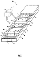
- High speed movement of paper can be enabled by use of independently adjustable mechanical movers such as differential rollers, or more advantageously, with air jets that support and move paper through a paper processing system such as a xerographic apparatus, laser printer, or electrostatic ink jet printer.
- the paper handling system includes a thermal marking unit (typically an infrared laser) for inducing a localized temperature gradient on a region of paper moving through the paper handling system.
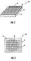
- a thermal sensing unit typically a two dimensional infrared sensing array, constructed using conventional micro electrical mechanical systems (MEMS) technology
- MEMS micro electrical mechanical systems
- a paper movement calculating module is connected to the thermal tracking unit, with the paper movement calculating module determining paper movement relative to the MEMS type thermal sensing unit based on determination of a centroid of the induced localized temperature gradient.
- a paper motion control unit connected to the paper movement calculating module is used to modify paper movement (for example, by selectively increasing or decreasing velocity of air jets impacting defined regions of the paper) to nearly instantaneously correct for paper misalignments.
- a thermal sensing unit 40 typically positioned adjacent to the thermal marking unit 30 (within a few meters, or often within a few centimeters) is used to measure object temperatures over the region of paper 12 having the induced localized temperature gradient 34, and pass this temperature information to a temperature analysis unit 50 capable of calculating movement of paper 12, including its position and velocity, relative to the thermal sensing unit 40. Using this calculated movement information, a motion control unit 52 connected to the temperature analysis unit sends control signals to modify movement of paper 12.
- the sensor measured temperature gradient in one, two, or three dimensions) to accurately determine position of the thermal marking (and consequently the paper 12).
- This positional information is passed to the motion control unit 52, which sends signals to selected air jets 26 to correct the misalignment, bringing the paper 12 back into an aligned position 18, ready for further processing by system 10.
- the present invention allows for thermal tracking, manipulation and control of a wide variety of objects and processes.
- the description of the present invention in conjunction with air jet conveyer 20 is for illustrative purposes only, and in suitable circumstances the conveyor 20 can be replaced by belts, friction drives, slides, chutes, mechanical grippers, vacuum attachment mechanisms, or any other conventional conveyor or drive mechanism.
- other articles of manufacture including those composed of plastics, ceramics, metals, wood, or any other conventional material, can be thermally tracked according to the present invention.
- Thermal tracking can also be employed to control movement of processing machinery.
- belts or rollers of xerographic copiers or other machinery having moving parts can be transiently marked with thermal indicia, the thermal indicia being thermally tracked to ensure proper speed, position, or rotational velocity of the moving parts.
- the present invention can be used with ordinary irregular articles capable of being visually or mechanically distinguished by appropriate imaging/identification systems
- the present invention is of particular utility in conjunction with processes that require precise high speed movement of delicate and visually featureless material.
- marking indicia such as inks, dyes, or physical cuts, notches or perforations.
- examples of such materials include rolls or sheets of paper, extruded plastics, metallic foils, wires, silicon wafers, high quality ceramics or machined parts, or even optical fibers.
- the present invention permits ready detection and correction of rotations, slight misalignments, or other orientation problems that can be difficult to quickly detect and provide suitable movement compensation for without application of undesirable markings to an otherwise featureless object.
- the thermal sensing unit 40 In order to ascertain object position properly, the thermal sensing unit 40 must be reliable and accurate, having a spatial, thermal, and temporal resolution sufficient for thermal tracking of a relatively small area (typically less than one square centimeter) at less than about 1/10 of a degree Celsius temperature gradient intervals.
- relatively low temperature elevations of a region of an object typically in the range of 10 to 100 degrees Celsius over ambient (ambient taken as about 20 degrees Celsius) are used.
- ambient taken as about 20 degrees Celsius
- even smaller temperature gradients may be employed. For example, if sinusoidal heat is applied to an object, temperature elevations as small as 1/100 of a degree Celsius may be detected after conventional signal processing techniques are used to filter out low frequency temperature changes.
- the thermal sensing unit 40 is a two dimensional MEMS-type sensor array 41.
- the sensor array 41 includes a substrate 43, typically silicon, that may be coated with single or multiple layers of doped silicon, polysilicon, silicon nitride, silicon, silicon oxide, oxynitride, or aluminum.
- a plurality of upwardly extending arms 42 that provide thermal isolation and enhance spatial resolution of the array 41 are attached to the substrate 43, with each arm 42 terminating in a thermally sensitive diode 44.
- a sensor array 41 will have overall dimensions between about one millimeter square to about one centimeter square, with anywhere from about 100 to 100,000 separate arms being used to support thermally sensitive diodes. In a most preferred embodiment, overall dimensions of between about 1 millimeter and 1 centimeter, with between about 100 and 100,000 thermally sensitive diodes being sufficient for measurement of temperature gradients with a desired spatial resolution
- Figure 5 illustrates the isotemperature gradient 146 in response to intermittent application of a heat spot (for example by a laser, not shown) as object 100 linearly passes in direction 71.
- a heat spot for example by a laser, not shown
- the two dimensional position of object 100 can readily be determined by calculation of centroid 156 of the temperature gradient. Again, it is possible to determine velocity of object 100, based on the direction and extent of broadening of the temperature gradient 146 as the object 100 moves away from the heat source and cools.
- Figures 6 and 7 illustrate possible thermal tracking schemes using multiple spaced apart thermal markings 147 and 148.
- Figure 7 illustrates application of periodic temperature pulses at discrete intervals to an object 100 to allow for accurate velocity determination.
- Figures 8-11 illustrate a few possible methods for heating paper 12 in addition to laser heating (heating via coherent radiation) as previously discussed in relation to Figure 1.
- a resistance element 82 connected to an electrical power source 80 can be used to provide a low cost and relatively steady source of radiative thermal energy to paper 12 moving in direction 73.
- Use of this resistance element 82 for heating an object would be expected to yield a isotemperature gradient qualitatively similar to that indicated in Figure 4.
Landscapes
- Physics & Mathematics (AREA)
- General Physics & Mathematics (AREA)
- Engineering & Computer Science (AREA)
- Mechanical Engineering (AREA)
- Length Measuring Devices By Optical Means (AREA)
- Handling Of Sheets (AREA)
- Length Measuring Devices With Unspecified Measuring Means (AREA)
- Delivering By Means Of Belts And Rollers (AREA)
- Control Of Position Or Direction (AREA)
Applications Claiming Priority (2)
| Application Number | Priority Date | Filing Date | Title |
|---|---|---|---|
| US08/583,240 US5682331A (en) | 1996-01-05 | 1996-01-05 | Motion tracking using applied thermal gradients |
| US583240 | 1996-01-05 |
Publications (2)
| Publication Number | Publication Date |
|---|---|
| EP0783106A1 true EP0783106A1 (fr) | 1997-07-09 |
| EP0783106B1 EP0783106B1 (fr) | 2002-04-24 |
Family
ID=24332282
Family Applications (1)
| Application Number | Title | Priority Date | Filing Date |
|---|---|---|---|
| EP96309523A Expired - Lifetime EP0783106B1 (fr) | 1996-01-05 | 1996-12-27 | Poursuite d'un mouvement à l'aide des gradients thermiques appliqués |
Country Status (4)
| Country | Link |
|---|---|
| US (1) | US5682331A (fr) |
| EP (1) | EP0783106B1 (fr) |
| JP (1) | JPH09237121A (fr) |
| DE (1) | DE69620857T2 (fr) |
Cited By (1)
| Publication number | Priority date | Publication date | Assignee | Title |
|---|---|---|---|---|
| EP0845430A3 (fr) * | 1996-11-26 | 1999-03-17 | Xerox Corporation | Système de manipulation de papier ayant des structures de commande encastrées |
Families Citing this family (24)
| Publication number | Priority date | Publication date | Assignee | Title |
|---|---|---|---|---|
| US6148248A (en) * | 1997-12-02 | 2000-11-14 | Zhongxue Gan | Apparatus and method for lobing and thermal-damage control in shoe centerless grinding |
| US6027112A (en) * | 1998-03-02 | 2000-02-22 | Xerox Corporation | Adaptive multiagent control system for controlling object motion with smart matter |
| US6039316A (en) * | 1998-03-02 | 2000-03-21 | Xerox Corporation | Multi-hierarchical control system for controlling object motion with smart matter |
| GB2360412B (en) * | 2000-03-13 | 2002-04-03 | Infrared Integrated Syst Ltd | The detection of obstacles in surveillance systems using pyroelectric arrays |
| CA2391171C (fr) * | 2002-06-20 | 2010-01-12 | Cashcode Company Inc. | Detecteur de mouvement pour objets plats |
| US7959517B2 (en) * | 2004-08-31 | 2011-06-14 | Acushnet Company | Infrared sensing launch monitor |
| US7918389B2 (en) * | 2007-05-15 | 2011-04-05 | Corning Incorporated | Method and system for tracking unfinished ceramic structures during manufacture |
| US9326689B2 (en) | 2012-05-08 | 2016-05-03 | Siemens Medical Solutions Usa, Inc. | Thermally tagged motion tracking for medical treatment |
| CN103176442B (zh) * | 2012-08-27 | 2015-01-28 | 中国科学院国家天文台南京天文光学技术研究所 | 天文望远镜与umac控制器通讯的方法 |
| US10134267B2 (en) | 2013-02-22 | 2018-11-20 | Universal City Studios Llc | System and method for tracking a passive wand and actuating an effect based on a detected wand path |
| US9056736B2 (en) | 2013-07-15 | 2015-06-16 | Eastman Kodak Company | Media-tracking system using thermally-formed holes |
| US9429419B2 (en) | 2013-07-15 | 2016-08-30 | Eastman Kodak Company | Media-tracking system using deformed reference marks |
| US8931874B1 (en) | 2013-07-15 | 2015-01-13 | Eastman Kodak Company | Media-tracking system using marking heat source |
| US8960842B2 (en) * | 2013-07-15 | 2015-02-24 | Eastman Kodak Company | Media-tracking system using thermal fluoresence quenching |
| US9433870B2 (en) | 2014-05-21 | 2016-09-06 | Universal City Studios Llc | Ride vehicle tracking and control system using passive tracking elements |
| US9429398B2 (en) | 2014-05-21 | 2016-08-30 | Universal City Studios Llc | Optical tracking for controlling pyrotechnic show elements |
| US9600999B2 (en) | 2014-05-21 | 2017-03-21 | Universal City Studios Llc | Amusement park element tracking system |
| US10207193B2 (en) | 2014-05-21 | 2019-02-19 | Universal City Studios Llc | Optical tracking system for automation of amusement park elements |
| US10025990B2 (en) | 2014-05-21 | 2018-07-17 | Universal City Studios Llc | System and method for tracking vehicles in parking structures and intersections |
| US9616350B2 (en) | 2014-05-21 | 2017-04-11 | Universal City Studios Llc | Enhanced interactivity in an amusement park environment using passive tracking elements |
| US10061058B2 (en) | 2014-05-21 | 2018-08-28 | Universal City Studios Llc | Tracking system and method for use in surveying amusement park equipment |
| US10238979B2 (en) | 2014-09-26 | 2019-03-26 | Universal City Sudios LLC | Video game ride |
| CN113064805A (zh) * | 2021-03-29 | 2021-07-02 | 联想(北京)有限公司 | 一种电子设备的控制方法以及控制装置 |
| EP4589470A1 (fr) * | 2024-01-17 | 2025-07-23 | Aptiv Technologies AG | Marquage thermique pour suivi d'objet |
Citations (10)
| Publication number | Priority date | Publication date | Assignee | Title |
|---|---|---|---|---|
| DE2616443B2 (de) * | 1976-04-14 | 1978-02-09 | Grünzweig + Hartmann und Glasfaser AG, 6700 Ludwigshafen | Verfahren zur beruehrungslosen laengen- bzw. geschwindigkeitsmessung eines sich bewegenden bandes |
| EP0063659A1 (fr) * | 1981-04-27 | 1982-11-03 | Automated Packaging Systems, Inc. | Détecteur de repères |
| EP0080353A2 (fr) * | 1981-11-25 | 1983-06-01 | FAG KUGELFISCHER GEORG SCHÄFER Kommanditgesellschaft auf Aktien | Appareil et méthode pour mesurer un profil de températures |
| DE3508257A1 (de) * | 1985-03-08 | 1986-09-11 | Roland 7114 Pfedelbach Wöhrl | Verfahren zum messen der geschwindigkeit mit hilfe von markierungen |
| JPS62282209A (ja) * | 1986-05-31 | 1987-12-08 | Nec Home Electronics Ltd | エンコ−ダ |
| US4777368A (en) * | 1986-08-28 | 1988-10-11 | University Of Tennessee | Apparatus and method for noncontact measurement of the velocity of a moving mass |
| GB2265361A (en) * | 1992-03-23 | 1993-09-29 | Heidelberger Druckmasch Ag | Device for controlling the lateral position of a web |
| US5258610A (en) * | 1992-09-02 | 1993-11-02 | Motorola, Inc. | Method and apparatus for sensing the presence of a sheet by sheet causing attenuation of radiation |
| GB2286822A (en) * | 1994-02-28 | 1995-08-30 | Rockwell International Corp | Continuous web printing press with page cutting control |
| DE19513861A1 (de) * | 1995-04-12 | 1996-10-17 | Madrzak Zygmunt | Verfahren zum Messen von Oberflächen-Geschwindigkeit und Oberflächen-Länge von Materialien und Materialbahnen |
Family Cites Families (8)
| Publication number | Priority date | Publication date | Assignee | Title |
|---|---|---|---|---|
| US3682554A (en) * | 1970-06-19 | 1972-08-08 | Reliance Electric Co | Non-contact measurement method and apparatus |
| US4662757A (en) * | 1984-05-18 | 1987-05-05 | Rca Corporation | Motion tracking system and method |
| US4662756A (en) * | 1984-05-18 | 1987-05-05 | Rca Corporation | Motion tracking device |
| US4861088A (en) * | 1986-09-04 | 1989-08-29 | Fedrigo Joseph G | Vehicle tailgate assembly |
| US4867054A (en) * | 1988-01-26 | 1989-09-19 | Thermo Electron Web Systems, Inc. | Caliper control system |
| US5021673A (en) * | 1989-10-10 | 1991-06-04 | Unisys Corp. (Formerly Burroughs Corp.) | Web transport with anti-skew arrangement |
| US5021676A (en) * | 1989-10-10 | 1991-06-04 | Unisys Corp. | Document-skew detection with photosensors |
| US5120976A (en) * | 1990-07-25 | 1992-06-09 | The Boeing Company | Strip lay-up verification system with width and centerline skew determination |
-
1996
- 1996-01-05 US US08/583,240 patent/US5682331A/en not_active Expired - Fee Related
- 1996-12-27 DE DE69620857T patent/DE69620857T2/de not_active Expired - Fee Related
- 1996-12-27 EP EP96309523A patent/EP0783106B1/fr not_active Expired - Lifetime
- 1996-12-27 JP JP8350832A patent/JPH09237121A/ja active Pending
Patent Citations (10)
| Publication number | Priority date | Publication date | Assignee | Title |
|---|---|---|---|---|
| DE2616443B2 (de) * | 1976-04-14 | 1978-02-09 | Grünzweig + Hartmann und Glasfaser AG, 6700 Ludwigshafen | Verfahren zur beruehrungslosen laengen- bzw. geschwindigkeitsmessung eines sich bewegenden bandes |
| EP0063659A1 (fr) * | 1981-04-27 | 1982-11-03 | Automated Packaging Systems, Inc. | Détecteur de repères |
| EP0080353A2 (fr) * | 1981-11-25 | 1983-06-01 | FAG KUGELFISCHER GEORG SCHÄFER Kommanditgesellschaft auf Aktien | Appareil et méthode pour mesurer un profil de températures |
| DE3508257A1 (de) * | 1985-03-08 | 1986-09-11 | Roland 7114 Pfedelbach Wöhrl | Verfahren zum messen der geschwindigkeit mit hilfe von markierungen |
| JPS62282209A (ja) * | 1986-05-31 | 1987-12-08 | Nec Home Electronics Ltd | エンコ−ダ |
| US4777368A (en) * | 1986-08-28 | 1988-10-11 | University Of Tennessee | Apparatus and method for noncontact measurement of the velocity of a moving mass |
| GB2265361A (en) * | 1992-03-23 | 1993-09-29 | Heidelberger Druckmasch Ag | Device for controlling the lateral position of a web |
| US5258610A (en) * | 1992-09-02 | 1993-11-02 | Motorola, Inc. | Method and apparatus for sensing the presence of a sheet by sheet causing attenuation of radiation |
| GB2286822A (en) * | 1994-02-28 | 1995-08-30 | Rockwell International Corp | Continuous web printing press with page cutting control |
| DE19513861A1 (de) * | 1995-04-12 | 1996-10-17 | Madrzak Zygmunt | Verfahren zum Messen von Oberflächen-Geschwindigkeit und Oberflächen-Länge von Materialien und Materialbahnen |
Non-Patent Citations (1)
| Title |
|---|
| PATENT ABSTRACTS OF JAPAN vol. 12, no. 170 (P - 705) 20 May 1988 (1988-05-20) * |
Cited By (1)
| Publication number | Priority date | Publication date | Assignee | Title |
|---|---|---|---|---|
| EP0845430A3 (fr) * | 1996-11-26 | 1999-03-17 | Xerox Corporation | Système de manipulation de papier ayant des structures de commande encastrées |
Also Published As
| Publication number | Publication date |
|---|---|
| DE69620857T2 (de) | 2002-08-14 |
| EP0783106B1 (fr) | 2002-04-24 |
| DE69620857D1 (de) | 2002-05-29 |
| JPH09237121A (ja) | 1997-09-09 |
| US5682331A (en) | 1997-10-28 |
Similar Documents
| Publication | Publication Date | Title |
|---|---|---|
| US5691921A (en) | Thermal sensors arrays useful for motion tracking by thermal gradient detection | |
| US5682331A (en) | Motion tracking using applied thermal gradients | |
| EP1828713B1 (fr) | Procede et appareil de mesure de l epaisseur de films minces | |
| TWI861734B (zh) | 基板固持器總成以及具有基板高度位置控制的噴墨印表機 | |
| US8760669B2 (en) | Method of measuring the thickness of a moving web | |
| EP1226954B1 (fr) | Contrôle du registre des lignes d'impression et des couleurs pour impression multi-balayage | |
| EP0563489B1 (fr) | Dispositif autocalibrant à deux capteurs mesurant la température sans contact | |
| WO2013182562A1 (fr) | Dispositif d'écriture optique pour feuilles flexibles | |
| US9304097B2 (en) | Method for aligning patterns on a substrate | |
| US9291588B2 (en) | System for forming aligned patterns on a substrate | |
| KR101121680B1 (ko) | 선형 엔코더를 이용한 정밀 인쇄 방법 및 장치 | |
| KR101232890B1 (ko) | 선형 엔코더를 이용한 정밀 인쇄 방법 및 장치 | |
| Ashauer et al. | Thermal characterization of microsystems by means of high-resolution thermography | |
| KR101294358B1 (ko) | 선형 엔코더를 이용한 정밀 인쇄 방법 및 장치 | |
| US20240385539A1 (en) | Image capturing apparatus and image capturing method | |
| KR102345439B1 (ko) | 롤투롤 노광 시스템 | |
| US7480053B2 (en) | Position detection based on two-directional correlation | |
| US7651873B1 (en) | Method relating to the accurate positioning of a semiconductor wafer | |
| KR101698072B1 (ko) | 롤투롤 공정에서 정렬패턴을 이용한 대상물의 거동 감지 방법 | |
| JP2020082507A (ja) | 印刷装置 |
Legal Events
| Date | Code | Title | Description |
|---|---|---|---|
| PUAI | Public reference made under article 153(3) epc to a published international application that has entered the european phase |
Free format text: ORIGINAL CODE: 0009012 |
|
| AK | Designated contracting states |
Kind code of ref document: A1 Designated state(s): DE FR GB |
|
| 17P | Request for examination filed |
Effective date: 19980109 |
|
| 17Q | First examination report despatched |
Effective date: 20001130 |
|
| GRAG | Despatch of communication of intention to grant |
Free format text: ORIGINAL CODE: EPIDOS AGRA |
|
| GRAG | Despatch of communication of intention to grant |
Free format text: ORIGINAL CODE: EPIDOS AGRA |
|
| GRAG | Despatch of communication of intention to grant |
Free format text: ORIGINAL CODE: EPIDOS AGRA |
|
| GRAH | Despatch of communication of intention to grant a patent |
Free format text: ORIGINAL CODE: EPIDOS IGRA |
|
| REG | Reference to a national code |
Ref country code: GB Ref legal event code: IF02 |
|
| GRAH | Despatch of communication of intention to grant a patent |
Free format text: ORIGINAL CODE: EPIDOS IGRA |
|
| GRAA | (expected) grant |
Free format text: ORIGINAL CODE: 0009210 |
|
| AK | Designated contracting states |
Kind code of ref document: B1 Designated state(s): DE FR GB |
|
| REG | Reference to a national code |
Ref country code: GB Ref legal event code: FG4D |
|
| REF | Corresponds to: |
Ref document number: 69620857 Country of ref document: DE Date of ref document: 20020529 |
|
| ET | Fr: translation filed | ||
| PLBE | No opposition filed within time limit |
Free format text: ORIGINAL CODE: 0009261 |
|
| STAA | Information on the status of an ep patent application or granted ep patent |
Free format text: STATUS: NO OPPOSITION FILED WITHIN TIME LIMIT |
|
| 26N | No opposition filed |
Effective date: 20030127 |
|
| PGFP | Annual fee paid to national office [announced via postgrant information from national office to epo] |
Ref country code: FR Payment date: 20031210 Year of fee payment: 8 |
|
| PGFP | Annual fee paid to national office [announced via postgrant information from national office to epo] |
Ref country code: GB Payment date: 20031224 Year of fee payment: 8 |
|
| PGFP | Annual fee paid to national office [announced via postgrant information from national office to epo] |
Ref country code: DE Payment date: 20040108 Year of fee payment: 8 |
|
| PG25 | Lapsed in a contracting state [announced via postgrant information from national office to epo] |
Ref country code: GB Free format text: LAPSE BECAUSE OF NON-PAYMENT OF DUE FEES Effective date: 20041227 |
|
| PG25 | Lapsed in a contracting state [announced via postgrant information from national office to epo] |
Ref country code: DE Free format text: LAPSE BECAUSE OF NON-PAYMENT OF DUE FEES Effective date: 20050701 |
|
| GBPC | Gb: european patent ceased through non-payment of renewal fee |
Effective date: 20041227 |
|
| PG25 | Lapsed in a contracting state [announced via postgrant information from national office to epo] |
Ref country code: FR Free format text: LAPSE BECAUSE OF NON-PAYMENT OF DUE FEES Effective date: 20050831 |
|
| REG | Reference to a national code |
Ref country code: FR Ref legal event code: ST |