EP0783131A2 - Méthode d'assemblage d'une cassette pour films photographiques. - Google Patents
Méthode d'assemblage d'une cassette pour films photographiques. Download PDFInfo
- Publication number
- EP0783131A2 EP0783131A2 EP97103291A EP97103291A EP0783131A2 EP 0783131 A2 EP0783131 A2 EP 0783131A2 EP 97103291 A EP97103291 A EP 97103291A EP 97103291 A EP97103291 A EP 97103291A EP 0783131 A2 EP0783131 A2 EP 0783131A2
- Authority
- EP
- European Patent Office
- Prior art keywords
- film
- spool
- shell
- cassette
- photographic film
- Prior art date
- Legal status (The legal status is an assumption and is not a legal conclusion. Google has not performed a legal analysis and makes no representation as to the accuracy of the status listed.)
- Withdrawn
Links
- 238000000034 method Methods 0.000 title claims abstract description 24
- 229920003023 plastic Polymers 0.000 claims abstract description 8
- 239000004033 plastic Substances 0.000 claims abstract description 8
- 238000004804 winding Methods 0.000 claims abstract description 4
- 238000003466 welding Methods 0.000 claims description 9
- 210000000078 claw Anatomy 0.000 claims description 8
- KKEYFWRCBNTPAC-UHFFFAOYSA-L terephthalate(2-) Chemical compound [O-]C(=O)C1=CC=C(C([O-])=O)C=C1 KKEYFWRCBNTPAC-UHFFFAOYSA-L 0.000 claims description 2
- 239000004793 Polystyrene Substances 0.000 claims 1
- 238000004026 adhesive bonding Methods 0.000 claims 1
- 230000013011 mating Effects 0.000 claims 1
- 229920002223 polystyrene Polymers 0.000 claims 1
- 230000008569 process Effects 0.000 abstract description 4
- 239000000463 material Substances 0.000 description 8
- 238000004458 analytical method Methods 0.000 description 2
- 230000004048 modification Effects 0.000 description 2
- 238000012986 modification Methods 0.000 description 2
- 230000008439 repair process Effects 0.000 description 2
- 239000000853 adhesive Substances 0.000 description 1
- 230000001070 adhesive effect Effects 0.000 description 1
- 238000006073 displacement reaction Methods 0.000 description 1
- 229920002457 flexible plastic Polymers 0.000 description 1
- 238000007689 inspection Methods 0.000 description 1
- 238000004806 packaging method and process Methods 0.000 description 1
- 230000009467 reduction Effects 0.000 description 1
- 239000011347 resin Substances 0.000 description 1
- 229920005989 resin Polymers 0.000 description 1
- 238000000926 separation method Methods 0.000 description 1
Images


Classifications
-
- G—PHYSICS
- G03—PHOTOGRAPHY; CINEMATOGRAPHY; ANALOGOUS TECHNIQUES USING WAVES OTHER THAN OPTICAL WAVES; ELECTROGRAPHY; HOLOGRAPHY
- G03B—APPARATUS OR ARRANGEMENTS FOR TAKING PHOTOGRAPHS OR FOR PROJECTING OR VIEWING THEM; APPARATUS OR ARRANGEMENTS EMPLOYING ANALOGOUS TECHNIQUES USING WAVES OTHER THAN OPTICAL WAVES; ACCESSORIES THEREFOR
- G03B17/00—Details of cameras or camera bodies; Accessories therefor
- G03B17/26—Holders for containing light sensitive material and adapted to be inserted within the camera
-
- G—PHYSICS
- G03—PHOTOGRAPHY; CINEMATOGRAPHY; ANALOGOUS TECHNIQUES USING WAVES OTHER THAN OPTICAL WAVES; ELECTROGRAPHY; HOLOGRAPHY
- G03B—APPARATUS OR ARRANGEMENTS FOR TAKING PHOTOGRAPHS OR FOR PROJECTING OR VIEWING THEM; APPARATUS OR ARRANGEMENTS EMPLOYING ANALOGOUS TECHNIQUES USING WAVES OTHER THAN OPTICAL WAVES; ACCESSORIES THEREFOR
- G03B2217/00—Details of cameras or camera bodies; Accessories therefor
- G03B2217/26—Holders for containing light-sensitive material and adapted to be inserted within the camera
Definitions
- the present invention relates to a method for assembling a photographic film cassette.
- a method for assembling photographic film cassette is described in later published EP543182 A1.
- the trailing end portion of the photographic film has a pair of identical holes formed therein.
- the core of the spool has corresponding hook portions adapted to engage the holes of the trailing end portion of the film strip, so that the photographic film can be wound on the core by rotating the spool.
- WO91/11383 describes a strip material dispenser comprising a core for winding.
- the core has two lateral spindles which are coaxially aligned and are arranged spaced with respect to each other. Within the space a spindle of smaller diameter is arranged, connecting the two lateral spindles to each other.
- the spindle of smaller diameter is arranged offset with respect to the aligned axis of the two lateral spindles, so that when rotating the spool the smaller spindle circumscribes a circle around the axis of the core.
- the strip material is provided with a leader having a width smaller than or equal to the length of the smaller spindle.
- the leader is attached to the smaller spindle, and the core is rotated to wound at first the leader around the smaller spindle and thereafter the strip material onto the lateral spindles.
- the smaller width of the leader compared to the width of the strip material may cause wrinkling of the leader if the spool and the strip are not held exactly perpendicular to each other. Due to the eccentric arrangement of smaller spindle with respect to the spool more of the length of the leader will be drawn into the cassette shell then may be convoluted onto the smaller spindle, so that the leader could not be closely wound onto the smaller spindle. This also increases the danger of wrinkling.
- GB-A-52-77723 describes a method for winding a film strip onto the spool of a film cassette using a flexible guide band piece.
- the flexible guide band piece is releasibly attached to the spool and protrudes out of the passage mouth of the cassette shell.
- the film is inserted along the upper surface of the guide band piece and is thereafter attached to the spool. Thereafter, the film, together with the guide band piece, is wound onto the spool.
- EP442501 A3 describes the photographic film cassette for containing a photographic film wound around a spool, arranged in a cassette shell in light-tight manner. Rotation of the spool causes a film leader to advance out of the cassette shell.
- the shell has to two shell halves each moulded from plastic.
- the ultrasonic welding is indispensable to attach the plastic shell halves since plastic has a low degree of heat tolerance.
- vibrations are generated due to the ultrasonic wave, which causes the photographic film to be scratched.
- an assembling machine is to get out of order, it takes much time to analyse its cause as well as to repair the assembling machine in a dark room compared with a lighted room, resulting in reduction of operation efficiency and increase of burden to the operator. If the darkroom is switched to be lighted for analyses and repair, a lot of photographic films put in the assembly line will be damaged.
- a primary object of the present invention is to provide a method of assembling a photographic film cassette wherein ineffective process in the darkroom can be reduced.
- shell halves are joined together, for example, by ultrasonic welding, to form a cassette shell, while accommodating a spool in the cassette shell and, thereafter, the cassette shell is transported in a dark room, wherein a strip of photographic film is connected to the spool and wound about the spool by rotating the spool.
- a film connection sheet is secured to the spool and, thereafter, the spool is mounted in the cassette shell, while a free end of the film connection sheet is placed outside the cassette shell through a film passage mouth of the cassette shell.
- the photographic film is attached to the free end of the film connection sheet to be wound about the spool when assembling the photographic film cassette.
- a photographic film cassette 10 has a cassette shell 11 consisting of upper and lower shell halves 11a and 11b which are attached by ultrasonic welding.
- the upper and lower shell halves 11a and 11b have integrally formed respective port portions 12a and 12b which are mated together to form a film passage mouth 14 of the cassette shell 11, through which a photographic film 13 is let in and out of the cassette shell 11.
- a spool 15 having a core 16 and a pair of flanges 18.
- the core 16 is formed with a slit 16a having therein a pair of claws 16b.
- a trailing end 17a of a leader sheet 17 is secured to the core 16 through engagement between the claws 16b and holes 17b formed in the trailing end 17a.
- a trailing end 13a of the photographic film 13 is attached to a free end 17c of the leader sheet 17.
- the leader sheet 17 is formed of e.g., polysthyrene terephthalate and its length is predetermined such that the free end 17c of the leader sheet 17 slightly protrudes, e.g., about 15 mm, to the outside of the film passage mouth 14 when the shell halves 11a and 11b are jointed together after the spool 15 is accommodated therein.
- the flanges 18 are formed on both end portions of the core 16 and serve to prevent the photographic film 13 from loosening with its lateral edges being rubbed against the inner surfaces of the flanges 18 when the photographic film 13 is wound on the core 16.
- flexible plastic disks 19 are rotatably fitted on the core 16 at axially outside portions relative to the flanges 18.
- the disks 19 are formed integrally with circumferential ridges 19a.
- Lateral end surfaces of the upper and lower shell halves 11a and 11b are provided with semicircular cut-outs 20a and 20b which form circular openings 20 (Fig. 3) for exposing end surfaces 16d of the core 16 to the outside when the upper and lower shell halves are joined together.
- Annular ridges 22a and 22b are formed on the lateral inside end surfaces of the upper and lower shell halves 11a and 11b so as to project inwardly to position the disks 19 such that they will not move in the axial direction of the spool 15. But, the ridges 22a and 22b are not formed in the vicinity of the port portions 12a and 12b.
- a separation claw 24 is formed on an innermost part of the port portion 12b of the lower shell half 11b to peel a leading end of the photographic film 13 off from the roll of photographic film 13 and to lead it toward the film passage mouth 14 as the spool 15 is rotated together with the photographic film 13.
- the inside surfaces of the port portions 12a and 12b have light-trapping pieces 25 attached thereto.
- a lighted room as indicated by Block A the cassette shell halves 11a and 11b are first placed on an assembly line. Then, the light-trapping pieces 25 are cut from a long sheet of light-trapping material 27 wound in a roll, and attached to the port portions 12a and 12b of the cassette shell halves 11a and 11b. In the meantime, the leader sheet 17 is cut at the predetermined length from a continuous roll of leader sheet material 28, inserted in the slit 16a, and secured to the spool 15 via the claws 16b formed within the slit 16a.
- the disks 19 are formed from a long sheet of disk material 29 wound in a roll, and freely mounted on the both end portions of the core 16. Then, after the spool 15 is put in between the shell halves 11a and 11b with the free end 17c of the leader sheet 17 being slightly projected from the film passage mouth 14, the shell halves 11a and 11b are mated to each other and securely attached by ultrasonic welding using an ultrasonic welding horn 30.
- the cassette shell 11 with the leader sheet 17 projected from the film passage mouth 14 are transferred to a darkroom as indicated by Block B.
- the photographic film 13 is cut at a predetermined length from a long roll of photographic film 31.
- the trailing end 13c of the photographic film 13 is attached to the free end 17c of the leader sheet 17 projected from the film passage mouth 14 by e.g., a double-coated tape or an adhesive.
- the entire length of the photographic film 13 is wound in the cassette shell 11 by rotation of the spool 15 resulting in completion of the photographic film cassette 10.
- the photographic film cassette 10 is again transferred to the lighted room, and subjected to inspection and packaging operations.
- the photographic film cassettes 10 are shipped to various places.
- the leader sheet 17 may be formed integrally with the spool 15.
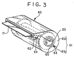
- Fig. 3 shows another embodiment of a photographic film cassette 60, wherein upper and lower shell halves 61a and 61b constituting a cassette shell 61 is prevented from the displacement during the ultrasonic welding.
- the upper shell half 61a is provided with projections 62 and 63 while the lower shell half 61b is provided with cut-outs 64 and 65 at corresponding portions to the projections 62 and 63.
- the projections 62 and 63 are provided at their inner portions with claws while the cut-outs 64 and 65 are provided at corresponding portions to the claws with recesses. Accordingly, the upper and lower shell halves 61a and 61b can be fixedly mated together by fitting the projections 62 and 63 in the respective cut-outs 64 and 65.
Landscapes
- Physics & Mathematics (AREA)
- General Physics & Mathematics (AREA)
- Storage Of Web-Like Or Filamentary Materials (AREA)
- Details Of Cameras Including Film Mechanisms (AREA)
- Structure And Mechanism Of Cameras (AREA)
- Photographic Processing Devices Using Wet Methods (AREA)
- Lining Or Joining Of Plastics Or The Like (AREA)
- Replacement Of Web Rolls (AREA)
Applications Claiming Priority (3)
| Application Number | Priority Date | Filing Date | Title |
|---|---|---|---|
| JP189731/92 | 1992-07-16 | ||
| JP4189731A JP2967960B2 (ja) | 1992-07-16 | 1992-07-16 | 写真フイルムパトローネの組立方法 |
| EP93111378A EP0579228B1 (fr) | 1992-07-16 | 1993-07-15 | Cassette pour pellicule photographique et procédé d'assemblage de celle-ci |
Related Parent Applications (2)
| Application Number | Title | Priority Date | Filing Date |
|---|---|---|---|
| EP93111378A Division EP0579228B1 (fr) | 1992-07-16 | 1993-07-15 | Cassette pour pellicule photographique et procédé d'assemblage de celle-ci |
| EP93111378.1 Division | 1993-07-15 |
Publications (2)
| Publication Number | Publication Date |
|---|---|
| EP0783131A2 true EP0783131A2 (fr) | 1997-07-09 |
| EP0783131A3 EP0783131A3 (fr) | 1997-07-16 |
Family
ID=16246248
Family Applications (2)
| Application Number | Title | Priority Date | Filing Date |
|---|---|---|---|
| EP93111378A Expired - Lifetime EP0579228B1 (fr) | 1992-07-16 | 1993-07-15 | Cassette pour pellicule photographique et procédé d'assemblage de celle-ci |
| EP97103291A Withdrawn EP0783131A3 (fr) | 1992-07-16 | 1993-07-15 | Méthode d'assemblage d'une cassette pour films photographiques |
Family Applications Before (1)
| Application Number | Title | Priority Date | Filing Date |
|---|---|---|---|
| EP93111378A Expired - Lifetime EP0579228B1 (fr) | 1992-07-16 | 1993-07-15 | Cassette pour pellicule photographique et procédé d'assemblage de celle-ci |
Country Status (4)
| Country | Link |
|---|---|
| US (1) | US5462240A (fr) |
| EP (2) | EP0579228B1 (fr) |
| JP (1) | JP2967960B2 (fr) |
| DE (1) | DE69318482T2 (fr) |
Cited By (1)
| Publication number | Priority date | Publication date | Assignee | Title |
|---|---|---|---|---|
| EP0907099A3 (fr) * | 1997-10-02 | 1999-06-09 | Fuji Photo Film Co., Ltd. | Méthode et appareil pour le traitement de film photographique photosensible |
Families Citing this family (6)
| Publication number | Priority date | Publication date | Assignee | Title |
|---|---|---|---|---|
| JPH07311443A (ja) * | 1994-05-17 | 1995-11-28 | Fuji Photo Film Co Ltd | 写真フイルムパトローネの組み立て方法及び装置 |
| EP0685758B1 (fr) * | 1994-05-24 | 2000-08-23 | Fuji Photo Film Co., Ltd. | Dispositif d'assemblage de cassettes de film photographique |
| JP3614974B2 (ja) * | 1996-04-24 | 2005-01-26 | 富士写真フイルム株式会社 | 写真フイルムの巻込み方法及び装置 |
| DE69737426T2 (de) * | 1996-09-04 | 2007-06-14 | Fuji Photo Film Co., Ltd., Fujinomiya | Verfahren und Vorrichtung zur Herstellung von Fotorollfilm |
| US6179594B1 (en) | 1999-05-03 | 2001-01-30 | Dynisco, Inc. | Air-cooled shaft seal |
| US6213745B1 (en) | 1999-05-03 | 2001-04-10 | Dynisco | High-pressure, self-lubricating journal bearings |
Family Cites Families (15)
| Publication number | Priority date | Publication date | Assignee | Title |
|---|---|---|---|---|
| US2616634A (en) * | 1949-04-01 | 1952-11-04 | Melkon Onnig Diran | Film magazine |
| US2662696A (en) * | 1951-03-29 | 1953-12-15 | Graflex Inc | Film cartridge for photographic cameras |
| US2719679A (en) * | 1952-09-23 | 1955-10-04 | Graflex Inc | Means for engaging photographic film to connect the film to the spool or core of a cassette |
| US3003712A (en) * | 1959-03-03 | 1961-10-10 | Graflex Inc | Take-up spool for photographic cameras |
| US3640480A (en) * | 1970-03-09 | 1972-02-08 | Matix Corp | Scroll stripping method and apparatus |
| JPS5277723A (en) * | 1975-12-24 | 1977-06-30 | Fuji Photo Film Co Ltd | Film wind up process and cassette |
| US4166588A (en) * | 1978-09-11 | 1979-09-04 | Kreonite Inc. | Self-threading take-up magazine for a photographic printer |
| EP0135372A3 (fr) * | 1983-09-16 | 1986-01-02 | R.P. Scherer Corporation | Capsule en gélatine et procédé et appareil de soudage ultrasonique des capsules |
| US4955555A (en) * | 1983-10-31 | 1990-09-11 | Eastman Kodak Company | Leader-retracting film magazine and method for enclosing film |
| DE3671303D1 (de) * | 1986-01-20 | 1990-06-21 | Agfa Gevaert Nv | Lichtdicht verpackte rolle aus lichtempfindlichem material. |
| US4834306A (en) * | 1988-03-25 | 1989-05-30 | Eastman Kodak Company | Film cassette |
| EP0436767A3 (en) * | 1990-01-12 | 1992-08-26 | Fuji Photo Film Co., Ltd. | Film cassette |
| FR2657861B1 (fr) * | 1990-02-05 | 1992-06-12 | Kodak Pathe | Emballage distributeur pour materiau en bande. |
| EP0442501B1 (fr) * | 1990-02-15 | 1997-06-18 | Fuji Photo Film Co., Ltd. | Coffret pour bobines de film photographique |
| US5215273A (en) * | 1991-11-19 | 1993-06-01 | Eastman Kodak Company | Film unwinding apparatus |
-
1992
- 1992-07-16 JP JP4189731A patent/JP2967960B2/ja not_active Expired - Fee Related
-
1993
- 1993-07-15 EP EP93111378A patent/EP0579228B1/fr not_active Expired - Lifetime
- 1993-07-15 DE DE69318482T patent/DE69318482T2/de not_active Expired - Fee Related
- 1993-07-15 EP EP97103291A patent/EP0783131A3/fr not_active Withdrawn
- 1993-07-15 US US08/091,627 patent/US5462240A/en not_active Expired - Lifetime
Cited By (6)
| Publication number | Priority date | Publication date | Assignee | Title |
|---|---|---|---|---|
| EP0907099A3 (fr) * | 1997-10-02 | 1999-06-09 | Fuji Photo Film Co., Ltd. | Méthode et appareil pour le traitement de film photographique photosensible |
| US6317951B1 (en) | 1997-10-02 | 2001-11-20 | Fuji Photo Film Co., Ltd. | Method of and apparatus for processing photographic photosensitive film |
| US6427306B2 (en) | 1997-10-02 | 2002-08-06 | Fuji Photo Film Co., Ltd. | Method of and apparatus for processing photographic photosensitive film |
| US6490783B2 (en) | 1997-10-02 | 2002-12-10 | Fuji Photo Film Co., Ltd. | Method of and apparatus for processing photographic photosensitive film |
| US6681478B2 (en) | 1997-10-02 | 2004-01-27 | Fuji Photo Film Co., Ltd. | Method of and apparatus for processing photographic photosensitive film |
| US6704999B2 (en) | 1997-10-02 | 2004-03-16 | Fuji Photo Film Co., Ltd. | Method of and apparatus for processing photographic photosensitive film |
Also Published As
| Publication number | Publication date |
|---|---|
| EP0579228A2 (fr) | 1994-01-19 |
| DE69318482T2 (de) | 1998-09-17 |
| US5462240A (en) | 1995-10-31 |
| EP0579228A3 (fr) | 1994-01-26 |
| EP0783131A3 (fr) | 1997-07-16 |
| JP2967960B2 (ja) | 1999-10-25 |
| DE69318482D1 (de) | 1998-06-18 |
| JPH0635128A (ja) | 1994-02-10 |
| EP0579228B1 (fr) | 1998-05-13 |
Similar Documents
| Publication | Publication Date | Title |
|---|---|---|
| EP0334324B1 (fr) | Cassette pour films | |
| EP0334325B1 (fr) | Cassette pour films | |
| EP0227435B1 (fr) | Récipient à jeter, étanche à la lumière | |
| US5031853A (en) | Film-thrusting cassette | |
| EP0783131A2 (fr) | Méthode d'assemblage d'une cassette pour films photographiques. | |
| US5711493A (en) | Method and apparatus for storing and dispensing a roll of photographic web | |
| US6491246B1 (en) | Pinch spools one-time use cameras apparatus and methods | |
| US5031855A (en) | Film-thrusting cassette | |
| US4809923A (en) | Light-tight film reel | |
| US3712557A (en) | Cassette and supply reel for use in cassette-loaded cinematographic apparatus | |
| US6622365B2 (en) | Pinch quill, apparatus, and film winding method | |
| US6190061B1 (en) | Photographic film unit and one-time use camera | |
| US5105604A (en) | Method for light-tightly enclosing a photosensitive web roll | |
| US5181672A (en) | Photograhic film cassette | |
| JPH0453648Y2 (fr) | ||
| US5709022A (en) | Method and apparatus for assembling photographic film cassette | |
| JP2980138B2 (ja) | 写真フイルムカートリッジ | |
| EP0525615B1 (fr) | Emballage comprenant une enveloppe flexible étanche à la lumière pour un rouleau photosensible et son procédé de fabrication | |
| US5893001A (en) | Film cassette | |
| JP3200711B2 (ja) | ロールフィルム収納カートリッジ及びその組立方法 | |
| JPH06214346A (ja) | フィルムパトローネ | |
| JPH0750082A (ja) | テープガイド、テープガイドの製造方法及びテープカセットの製造方法 | |
| EP0554921A2 (fr) | Cassette de film | |
| JPH11212216A (ja) | ロール状感光材料用遮光フランジ及びロール状感光材料 | |
| JPH02264248A (ja) | 写真フィルムパトローネ |
Legal Events
| Date | Code | Title | Description |
|---|---|---|---|
| PUAI | Public reference made under article 153(3) epc to a published international application that has entered the european phase |
Free format text: ORIGINAL CODE: 0009012 |
|
| PUAL | Search report despatched |
Free format text: ORIGINAL CODE: 0009013 |
|
| AC | Divisional application: reference to earlier application |
Ref document number: 579228 Country of ref document: EP |
|
| AK | Designated contracting states |
Kind code of ref document: A2 Designated state(s): DE FR NL |
|
| AK | Designated contracting states |
Kind code of ref document: A3 Designated state(s): DE FR NL |
|
| 17P | Request for examination filed |
Effective date: 19971127 |
|
| 17Q | First examination report despatched |
Effective date: 19981204 |
|
| STAA | Information on the status of an ep patent application or granted ep patent |
Free format text: STATUS: THE APPLICATION IS DEEMED TO BE WITHDRAWN |
|
| 18D | Application deemed to be withdrawn |
Effective date: 19990420 |