EP0783142B1 - Sicherheitsvorrichtung für eine Tonerbildfixiervorrichtung - Google Patents
Sicherheitsvorrichtung für eine Tonerbildfixiervorrichtung Download PDFInfo
- Publication number
- EP0783142B1 EP0783142B1 EP96120850A EP96120850A EP0783142B1 EP 0783142 B1 EP0783142 B1 EP 0783142B1 EP 96120850 A EP96120850 A EP 96120850A EP 96120850 A EP96120850 A EP 96120850A EP 0783142 B1 EP0783142 B1 EP 0783142B1
- Authority
- EP
- European Patent Office
- Prior art keywords
- roller
- fixing
- temperature sensing
- heat
- temperature
- Prior art date
- Legal status (The legal status is an assumption and is not a legal conclusion. Google has not performed a legal analysis and makes no representation as to the accuracy of the status listed.)
- Expired - Lifetime
Links
- 230000002159 abnormal effect Effects 0.000 claims description 8
- 238000010438 heat treatment Methods 0.000 claims description 6
- 239000011231 conductive filler Substances 0.000 claims description 4
- 230000002093 peripheral effect Effects 0.000 claims 1
- 230000004044 response Effects 0.000 description 11
- 238000000034 method Methods 0.000 description 10
- 230000000630 rising effect Effects 0.000 description 8
- 229920002379 silicone rubber Polymers 0.000 description 7
- 230000000694 effects Effects 0.000 description 6
- 229920005989 resin Polymers 0.000 description 6
- 239000011347 resin Substances 0.000 description 6
- 238000010276 construction Methods 0.000 description 5
- 239000000945 filler Substances 0.000 description 5
- 239000000463 material Substances 0.000 description 4
- 239000000779 smoke Substances 0.000 description 4
- 229910052782 aluminium Inorganic materials 0.000 description 3
- XAGFODPZIPBFFR-UHFFFAOYSA-N aluminium Chemical compound [Al] XAGFODPZIPBFFR-UHFFFAOYSA-N 0.000 description 3
- 230000008859 change Effects 0.000 description 3
- 238000010304 firing Methods 0.000 description 3
- 229910052751 metal Inorganic materials 0.000 description 3
- 239000002184 metal Substances 0.000 description 3
- 230000008569 process Effects 0.000 description 3
- 230000001012 protector Effects 0.000 description 3
- 229920003002 synthetic resin Polymers 0.000 description 3
- 239000000057 synthetic resin Substances 0.000 description 3
- XUIMIQQOPSSXEZ-UHFFFAOYSA-N Silicon Chemical compound [Si] XUIMIQQOPSSXEZ-UHFFFAOYSA-N 0.000 description 2
- 239000004809 Teflon Substances 0.000 description 2
- 229920006362 Teflon® Polymers 0.000 description 2
- 230000006835 compression Effects 0.000 description 2
- 238000007906 compression Methods 0.000 description 2
- 239000013013 elastic material Substances 0.000 description 2
- NBVXSUQYWXRMNV-UHFFFAOYSA-N fluoromethane Chemical compound FC NBVXSUQYWXRMNV-UHFFFAOYSA-N 0.000 description 2
- 230000007257 malfunction Effects 0.000 description 2
- 229920001343 polytetrafluoroethylene Polymers 0.000 description 2
- 239000004810 polytetrafluoroethylene Substances 0.000 description 2
- 230000009467 reduction Effects 0.000 description 2
- 229910052710 silicon Inorganic materials 0.000 description 2
- 239000010703 silicon Substances 0.000 description 2
- 239000004945 silicone rubber Substances 0.000 description 2
- 239000000126 substance Substances 0.000 description 2
- 230000007613 environmental effect Effects 0.000 description 1
- 230000001815 facial effect Effects 0.000 description 1
- 239000004519 grease Substances 0.000 description 1
- 229920006015 heat resistant resin Polymers 0.000 description 1
- 238000009413 insulation Methods 0.000 description 1
- 238000005259 measurement Methods 0.000 description 1
- 229920001721 polyimide Polymers 0.000 description 1
- 230000000391 smoking effect Effects 0.000 description 1
Images


Classifications
-
- G—PHYSICS
- G03—PHOTOGRAPHY; CINEMATOGRAPHY; ANALOGOUS TECHNIQUES USING WAVES OTHER THAN OPTICAL WAVES; ELECTROGRAPHY; HOLOGRAPHY
- G03G—ELECTROGRAPHY; ELECTROPHOTOGRAPHY; MAGNETOGRAPHY
- G03G15/00—Apparatus for electrographic processes using a charge pattern
- G03G15/20—Apparatus for electrographic processes using a charge pattern for fixing, e.g. by using heat
- G03G15/2003—Apparatus for electrographic processes using a charge pattern for fixing, e.g. by using heat using heat
- G03G15/2014—Apparatus for electrographic processes using a charge pattern for fixing, e.g. by using heat using heat using contact heat
- G03G15/2039—Apparatus for electrographic processes using a charge pattern for fixing, e.g. by using heat using heat using contact heat with means for controlling the fixing temperature
-
- G—PHYSICS
- G03—PHOTOGRAPHY; CINEMATOGRAPHY; ANALOGOUS TECHNIQUES USING WAVES OTHER THAN OPTICAL WAVES; ELECTROGRAPHY; HOLOGRAPHY
- G03G—ELECTROGRAPHY; ELECTROPHOTOGRAPHY; MAGNETOGRAPHY
- G03G15/00—Apparatus for electrographic processes using a charge pattern
- G03G15/20—Apparatus for electrographic processes using a charge pattern for fixing, e.g. by using heat
- G03G15/2003—Apparatus for electrographic processes using a charge pattern for fixing, e.g. by using heat using heat
- G03G15/2014—Apparatus for electrographic processes using a charge pattern for fixing, e.g. by using heat using heat using contact heat
- G03G15/2017—Structural details of the fixing unit in general, e.g. cooling means, heat shielding means
Definitions
- Toner image fixing devices used in electrophotographic type copying machines, facsimiles, printers and other instruments using electrophotographic process are generally of the thermal fixing type that fixes toner image on a recording medium by fusing.
- a fixing portion is composed of a fixing roller and pressure roller pressing the fixing roller. Either one or both rollers are heated. While the recording member passes a nip between the two rollers, a toner image formed on the recording member is fixed thereon by the effect of heat and pressure.
- the fixing roller is a thin-wall aluminum cylinder coated with well-releasable and heat-resistant synthetic resin, e.g., fluorocarbon resin (PFA, PTFE), and includes a heater lamp inserted in its center bore.
- the fixing roller is rotatably supported on a roller supporting member.
- the pressure roller is a metal roller coated with silicone rubber and is rotatably supported at both ends by a pair of pressure-roller supporting members. The pressure roller is pressed against the fixing roller at a constant force of compression coiled springs.
- the surface of the fixing roller is heated by the heater lamp mounted therein.
- Surface temperature of the fixing roller is controlled by a temperature adjusting circuit according to a signal from a roller-surface-temperature sensing means disposed near the fixing roller.
- the roller-surface-temperature sensing means comprises a temperature sensing element (e.g., thermistor) pressed against the surface of the fixing roller to minimize a disturbance.
- the fixing portion has heating means for heating and keeping the roller surface at a constant temperature to fuse toner on the recording medium. Accordingly, the temperature of the roller surface may abnormally rise if the roller-surface temperature control malfunctions due to abnormal operation of a main machine.
- the machine is provided with a safety device that may prevent occurrence of smoke and fire in the machine in the worst case.
- the safety device may be composed of a separate temperature sensing means and a separate control circuit or the temperature sensing means inserted in series in the heater lamp circuit.
- the safety device detects by the temperature sensing means that a temperature of the roller exceeds a specified value. It acts upon the control circuit to stop power supply to the heater lamp or directly switches off the heater lamp circuit.
- a temperature sensing element e.g., a thermostat, a temperature fuse and a thermal protector
- This temperature sensing element is usually disposed apart from the roller since the roller surface temperature rises gradually.
- Electrophotographic type printers and other machines that use electrophotographic process are also required to be of electro-energy-saving type.
- a most energy-consuming portion of an electrophotographic machine (printer) is a toner-image fixing device that consumes a large part of a total electric power consumption of the machine.
- the reduction of power consumption of the fixing device is an essential object of the electrophotographic machine.
- the conventional fixing device keeps its roller at a constant temperature even while print is not needed. Preheating of the roller is necessary for printing without waiting time.
- the fixing roller of a reduced heat-capacity can be so rapidly heated up that the conventional temperature sensing element can not response to a change of surface temperature of the roller. This means that abnormal temperature rising may not immediately be detected, causing smoke and fire in the machine. So, practical use of an energy-saving fixing device of a small heat capacity has not been realized because the safety operation can not be guaranteed.
- Document JP-A-58-118681 discloses such a method that a temperature sensing element is disposed apart from a roller and a heat-reflector is disposed behind the temperature sensing element to increase a sensing surface temperature of the element. Further, document JP-A-63-169680 discloses a temperature sensing element covered with a heat-conductive member, which butts upon a roller.
- Prior art document JP-A-56-001324 discloses a contact-type temperature detector wherein a temperature-sensing element is sandwiched between a resin sheet and an elastic body.
- the elastic body presses the temperature-sensing element against a roller with the resin sheet interposed therebetween.
- prior art document JP-A-2-145931 shows a temperature sensing element which is covered by a polyimid sheet and provided for sensing the temperature of a fixing roller. A space above the temperature sensing element is filled with silicon grease.
- the present invention provides a safety device as defined in claim 1.
- a safety device of a toner image fixing unit has a fast-response temperature sensing unit that includes a small heat-capacity type temperature sensing element (e.g., a temperature fuse, small-size thermostat, thermal protector and so on) and is in contact with a fixing roller through a sliding sheet.
- a small heat-capacity type temperature sensing element e.g., a temperature fuse, small-size thermostat, thermal protector and so on
- a well-heat-conductive filler or elastic member may be interposed between the temperature sensing unit and the sliding sheet to reduce a loss of heat transfer.
- the temperature sensing element is covered at its not-contacting surface (reverse to a surface contacting with a sliding sheet) with heat-insulating member preventing heat liberation.
- the heat-insulating member has a groove or a notch for engaging a protrusion of the temperature sensing element to fix the element and improve contact of the temperature sensing unit with the fixing roller.
- the contacting surface of the temperature sensing unit is formed to have the same curvature that the cylindrical surface of the fixing roller has by means of the insulating member and the filler or elastic member.
- Fig. 1 is a schematic construction view of a conventional toner-image fixing device.
- Fig. 2 is a schematic construction view of a toner-image fixing device to which a safety device according to the present invention can be applied.
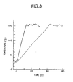
- Fig. 3 is a graph showing an increasing surface temperature of a fixing roller.
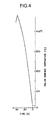
- Fig. 4 is a graph showing an abnormally increasing surface temperature of a fixing roller.
- Fig. 5 schematically illustrates a structure of a temperature sensing portion of a safety device according to the present invention.
- Fig. 6 schematically illustrates another structure of a temperature sensing portion of a safety device according to the present invention.
- Fig. 7 is a graph showing a working condition of a safety device when a surface temperature of a fixing roller abnormally rises.
- Fig. 1 is a schematic construction view of a conventional toner-image fixing device.
- a fixing portion is composed of a fixing roller 1 and pressure roller 2 pressing the fixing roller. Either one or both rollers are heated. While the recording member 6 passes a nip between the two rollers, a toner image formed on the recording member 6 is fixed thereon by the effect of heat and pressure.
- the fixing roller 1 is a thin-wall aluminum cylinder coated with well-releasable and heat-resistant synthetic resin, e.g., fluorocarbon resin (PFA, PTFE), and includes a heater lamp 5 inserted in its center bore.
- the fixing roller is rotatably supported on a roller supporting member 8.
- the pressure roller 2 is a metal roller coated with silicone rubber and is rotatably supported at both ends by a pair of pressure-roller supporting members 7. The pressure roller 2 is pressed against the fixing roller 1 at a constant force of compression coiled springs.
- the surface of the fixing roller 1 is heated by the heater lamp 5 mounted therein.
- Surface temperature of the fixing roller is controlled by a temperature adjusting circuit 9 according to a signal from a roller-surface-temperature sensing means 4 disposed near the fixing roller 1.
- the roller-surface-temperature sensing means 4 comprises a temperature sensing element (e.g., thermistor) pressed against the surface of the fixing roller to minimize a disturbance.
- the fixing portion has heating means for heating and keeping the roller surface at a constant temperature to fuse toner on the recording medium. Accordingly, the temperature of the roller surface may abnormally rise if the roller-surface temperature control malfunctions due to abnormal operation of a main machine.
- the machine is provided with a safety device 10 that may prevent occurrence of smoke and fire in the machine in the worst case.
- the safety device 10 may be composed of a separate temperature sensing means 3 and a separate control circuit 11 as shown in Fig. 1 or the temperature sensing means 3 inserted in series in the heater lamp circuit.
- the safety device 10 detects by the temperature sensing means 3 that a temperature of the roller exceeds a specified value. It acts upon the control circuit 11 to stop power supply to the heater lamp or directly switches off the heater lamp circuit.
- a temperature sensing element e.g., a thermostat, a temperature fuse and a thermal protector
- a temperature sensing element is usually used as means for detecting an abnormally rising temperature.
- the present invention relates to improvements of response of a temperature sensing unit of a safety device for sensing abnormal temperature rise of a fixing portion.
- Fig. 2 shows a construction of a fixing portion of a toner image fixing device using a safety device according to the present invention.
- the safety device is will be explained later in detail.
- the structure of a small heat-capacity fixing device and temperature rising characteristics of the device must be first described as follows:
- a fixing roller 12 is made of a small heat-capacity type whose inside diameter is 13 mm and wall thickness is 0.5 mm (a conventional fixing roller has an inside diameter of not less than 20 mm and a wall thickness of not less than 1.5 mm).
- the cylindrical surface of the fixing roller 12, like the conventional roller, is covered with a coat of synthetic resin that is well-releasable and well heat-resistant.
- the roller 12 contains therein a heater lamp 5 whose rated power is 400 W (800 W in the conventional device because of a large heat-capacity of the roller to be heated).
- a pressure roller 13 is a silicon rubber roller having an shaft made of metal whereto the silicon rubber is secured. The pressure roller 13 has a small diameter of 12 mm to attain a reduced heat-capacity (the conventional roller has a diameter of not less than 20 mm).
- the pressure member 18 is made of an elastic material having an excellent heat resistance. Namely, elastic member for pressing a recording medium against the fixing roller 12 is not rotatable but fixed so as to reduce mass of the pressure member, thus minimizing heat-transfer from the fixing roller.
- the pressure member 18, however, is inferior in paper feeding ability to the pressure roller, and its surface is therefore covered with a pressure sheet 19 that can reduce a friction force on the recording material 6 smaller than a friction force between the recording material 6 and the fixing roller 1.
- the recording material 6 is fed forward by the effect of a differential friction force.
- the surface temperature of the fixing roller is measured and the measurement result is shown in Fig. 3.
- the shown temperature characteristic curve indicates the fixing roller surface temperature changing with time on the condition that the roller surface temperature control is normally performed.
- a solid-line curve shows the change of the roller surface temperature of the fixing device relating to the present invention and a broken-line curve shows the change of the roller surface temperature of the conventional fixing unit.
- the rising time the time interval during which the roller surface temperature rises from a room temperature to a temperature necessary for fixing toner image (usually 150°C) is termed the rising time. It is apparent that the rising time of the embodiment as compared with the rising time (40 - 50 seconds) of the conventional unit is considerably shortened to 10 - 12 seconds. Consequently, printing can start with a shortest waiting time without heating the roller while no print is made.
- the fixing device having a so much reduced heat-capacity may involve the before mentioned danger that the fixing roller so fast heated over the limited value, generating smoke and fire in the fixing device.
- Fig. 4 shows the roller surface temperature of the fixing device in an abnormal condition.
- the roller surface temperature exceeds 400°C for 20 - 30 seconds after switching ON the heater lamp.
- the shown temperature curve is obtained in the fixing device with a temperature fuse (temperature sensing element) disposed apart by 5 mm from the roller surface.
- the temperature fuse did not act when the roller surface temperature increased over 450°C. It is very dangerous since the firing point of paper is 430°C - 450°C (namely, a recording paper sheet may get fire when passing the nip portion of the roller). Accordingly, the conventional safety device can not realize a power-saving fixing device having a small heat capacity.
- a temperature sensing portion of a safety device Referring to Figs. 5 and 6, the structure of a temperature sensing portion of a safety device according to the present invention is described as follows:
- a temperature fuse 14 is secured onto a heat-insulating member 15 that is made of heat-resistant silicon sponge manufactured by INOAC company (in the shown case).
- This heat-insulating member 15 is preferred to be elastic because its contact surface on a roller may be increased- In principle, any material having heat-insulating ability may be used. Engineering resin (e.g., polycabonate resin) and heat-resistant resin can be also applied.
- the heat-insulating member 15 has a groove or a slit that fits in shape a protruding portion of the temperature fuse so that the temperature sensing portion of the temperature fuse 14 is reliably abutted on a fixing roller 12 and the temperature fuse itself is accurately located.
- the heat-insulating member 15 is supported at the opposite side (reverse to the surface facing to the fixing roller) by springs or ribs (not shown). Namely, the temperature sensing means 3 (Fig. 2) is abutted against the fixing roller 12 by spring forces and/or by the effect of the elasticity of the heat-insulating member.
- the temperature fuse is surrounded tightly by a well-heat-conductive and electrically insulating filler 16, thus eliminating an air layer preventing heat-transfer.
- heat-resistant silicon rubber K3493 made by Shin-etsu Chemical Industry. It is also possible to use an elastic material having a high heat conductivity, insulation and high heat resistance.
- a sliding allowing sheet 17 is interposed between the filler 16 and the fixing roller to prevent the roller surface from wearing.
- a capton sheet of 25 ⁇ m made by Toray-Doupon Company.
- a sheet of Teflon may be used.
- the fixing roller 12 and the sliding allowing sheet 17 make a facial (not line) contact with each other by the effect of the filler and the heat-insulating member.
- Fig. 7 shows the effect of applying the safety device in the small-heat-capacity type fixing device.
- a curve shown in Fig. 7 indicates the roller surface temperature changing with time under an abnormal condition.
- the safety device can act and forcibly extinguish the heater lamp at 325°C (fairly lower than the firing point of paper) when for some reason or other the heater lamp is left burning. There is no fear of smoking or firing in an unusual condition. Accordingly, the small heat-capacity type fixing device with the safety device can be safely used.
- heat-resistant silicon rubber As the filler, heat-conductive and heat-resistant gel substance may be used instead of the silicon rubber.
- the safety device of the toner fixing device according to the present invention offers the following advantages:
- the temperature sensing unit is formed of a small heat-capacity temperature sensing element and the sliding sheet with heat-conductive filler or heat-conductive elastic body interposed therebetween and the temperature sensing element is abutted through the sliding sheet on the fixing roller, the heat transfer loss between the roller and the temperature sensing portion is reduced and the heat flow to the temperature sensing portion of the temperature sensing element is improved, thus an increased response of the safety device is attained.
- the temperature sensing element is covered with the heat-insulating member that prevents heat-transfer from the element surface reverse to the surface contacting with the roller surface, thus the heat-transfer to the temperature sensing portion of the temperature sensing element is improved and an increased response of the safety device is attained.
- the contacting surface of the temperature sensing unit is formed to have the same curvature as the fixing roller has by using the heat-insulating member, heat-conductive filler or elastic member: the contacting area of the temperature sensing unit can be increased and the heat-transfer ratio is thereby improved, thereby the safety device attains fast response.
- the heat-insulating member of the temperature sensing unit has a groove or a slit wherein the protruding portion of the temperature sensing element fit. Namely, the temperature sensing element can be correctly positioned relative to the fixing roller and its temperature sensing portion can keep smooth contact with the roller surface.
Landscapes
- Physics & Mathematics (AREA)
- General Physics & Mathematics (AREA)
- Fixing For Electrophotography (AREA)
- Control Or Security For Electrophotography (AREA)
- Control Of Temperature (AREA)
Claims (3)
- Sicherheitsvorrichtung (10) für eine Tonerbildfixiervorrichtung
welche in der Lage ist, einen abnormalen Temperaturanstieg einer Fixierwalze (12) zu messen und die elektrische Energiezufuhr der Heizeinrichtung abzuschalten, und welche ein Temperatursensorelement (14), ein Gleitblatt (17), welches sich auf der Fixierwalze (12) abstützt oder auf dieser aufliegt, ein wärmeleitfähiges Füllelement oder einen wärmeleitfähigen elastischen Körper (16) zum Auffüllen des Raums zwischen dem Gleitblatt (17) und dem Temperatursensorelement (14) und ein Druckelement (18) aufweist zum Andrücken eines Aufzeichnungsmediums gegen die Fixierwalze (12),
wobei das Temperatursensorelement (14) eine Oberfläche auf der Fixierwalzenauflageseite und eine gegenüberliegende Oberfläche aufweist, welche mit einem wärmeisolierendem Element (15) abgedeckt ist. - Sicherheitsvorrichtung (10) für eine Tonerbildfixiervorrichtung nach Anspruch 1,
bei welcher die Oberfläche des Temperatursensorelements (14) auf der Fixierwalzenauflageseite eine Krümmung besitzt, welche zur Umfangsoberfläche der Fixierwalze (12) passt oder mit dieser übereinstimmt. - Sicherheitsvorrichtung (10) für eine Tonerbildfixiervorrichtung nach Anspruch 1,
bei welcher das wärmeisolierende Element (15) eine Ausnehmung oder eine Kerbe aufweist, welche in ihrer Form mit einer Erhebung des Temperatursensorelements (14) korrespondiert und in der Lage ist, das Temperatursensorelement (14) in einer Stellung derart zu fixieren, dass die Temperatursensoroberfläche des Temperatursensorelements (14) plan oder gleichmäßig auf der Fixierwalze (12) aufliegt.
Applications Claiming Priority (3)
| Application Number | Priority Date | Filing Date | Title |
|---|---|---|---|
| JP33884495 | 1995-12-26 | ||
| JP338844/95 | 1995-12-26 | ||
| JP7338844A JPH09179439A (ja) | 1995-12-26 | 1995-12-26 | 定着装置の安全装置 |
Publications (4)
| Publication Number | Publication Date |
|---|---|
| EP0783142A2 EP0783142A2 (de) | 1997-07-09 |
| EP0783142A3 EP0783142A3 (de) | 1998-07-22 |
| EP0783142B1 true EP0783142B1 (de) | 2003-03-12 |
| EP0783142B8 EP0783142B8 (de) | 2003-06-25 |
Family
ID=18321961
Family Applications (1)
| Application Number | Title | Priority Date | Filing Date |
|---|---|---|---|
| EP96120850A Expired - Lifetime EP0783142B8 (de) | 1995-12-26 | 1996-12-23 | Sicherheitsvorrichtung für eine Tonerbildfixiervorrichtung |
Country Status (4)
| Country | Link |
|---|---|
| US (1) | US5890031A (de) |
| EP (1) | EP0783142B8 (de) |
| JP (1) | JPH09179439A (de) |
| DE (1) | DE69626618T2 (de) |
Families Citing this family (6)
| Publication number | Priority date | Publication date | Assignee | Title |
|---|---|---|---|---|
| JP3885485B2 (ja) * | 2000-11-13 | 2007-02-21 | ブラザー工業株式会社 | 熱定着装置および画像形成装置 |
| US6967308B1 (en) * | 2004-05-07 | 2005-11-22 | Dell Products L.P. | System and method for information handling system peripheral heating element thermal failsafe |
| EP1617301B1 (de) * | 2004-07-12 | 2010-10-20 | Brother Kogyo Kabushiki Kaisha | Fixiervorrichtung und damit ausgerüstete Bilderzeugungsvorrichtung |
| US20090097873A1 (en) * | 2007-10-16 | 2009-04-16 | Palo Alto Research Center Incorporated | Intermediate roller for sensing temperature of passing surfaces |
| JP7625893B2 (ja) * | 2021-02-26 | 2025-02-04 | ブラザー工業株式会社 | 加熱ユニット |
| CN114234155B (zh) * | 2021-11-29 | 2024-02-20 | 厦门普为光电科技有限公司 | 高安全性灯管及其提高温度保险丝保护范围的方法 |
Family Cites Families (12)
| Publication number | Priority date | Publication date | Assignee | Title |
|---|---|---|---|---|
| US3357249A (en) * | 1966-01-03 | 1967-12-12 | Xerox Corp | Temperature sensor |
| US3809855A (en) * | 1973-06-12 | 1974-05-07 | Ibm | Thermal sensing apparatus |
| JPS5833492B2 (ja) * | 1979-06-18 | 1983-07-20 | キヤノン株式会社 | 定着装置 |
| US4441827A (en) * | 1980-10-14 | 1984-04-10 | Andre Coderre | Travelling surface temperature probe |
| JPH0248903B2 (ja) | 1982-01-09 | 1990-10-26 | Canon Kk | Teichakusochi |
| JPS63169680A (ja) | 1987-01-08 | 1988-07-13 | Matsushita Electric Ind Co Ltd | 定着装置 |
| JPH02145931A (ja) * | 1988-11-28 | 1990-06-05 | Hitachi Ltd | 温度センサ及び前記温度センサを使用した複写機 |
| US4951096A (en) * | 1989-06-26 | 1990-08-21 | Eastman Kodak Company | Self-calibrating temperature control device for a heated fuser roller |
| JP2797736B2 (ja) * | 1991-02-21 | 1998-09-17 | キヤノン株式会社 | 定着装置 |
| EP0530618B1 (de) * | 1991-09-06 | 1997-12-03 | Konica Corporation | Fixiervorrichtung mit Temperaturmesseinrichtung |
| US5281793A (en) * | 1991-10-28 | 1994-01-25 | Xerox Corporation | Apparatus for positioning a temperature sensing element in temperature sensing relationship with a moving object |
| US5475200A (en) * | 1994-08-25 | 1995-12-12 | Xerox Corporation | Field replaceable thermistor wear tape |
-
1995
- 1995-12-26 JP JP7338844A patent/JPH09179439A/ja active Pending
-
1996
- 1996-12-23 US US08/771,533 patent/US5890031A/en not_active Expired - Lifetime
- 1996-12-23 DE DE69626618T patent/DE69626618T2/de not_active Expired - Lifetime
- 1996-12-23 EP EP96120850A patent/EP0783142B8/de not_active Expired - Lifetime
Also Published As
| Publication number | Publication date |
|---|---|
| JPH09179439A (ja) | 1997-07-11 |
| DE69626618T2 (de) | 2004-02-12 |
| US5890031A (en) | 1999-03-30 |
| DE69626618D1 (de) | 2003-04-17 |
| EP0783142A2 (de) | 1997-07-09 |
| EP0783142B8 (de) | 2003-06-25 |
| EP0783142A3 (de) | 1998-07-22 |
Similar Documents
| Publication | Publication Date | Title |
|---|---|---|
| US10809651B2 (en) | Heating device, fixing device, and image forming apparatus | |
| US10663898B2 (en) | Fixing apparatus | |
| CN108717253B (zh) | 定影装置 | |
| EP0632345B1 (de) | Bilderzeugungsgerät | |
| WO1998014837A1 (fr) | Dispositif de fixation a bande | |
| US20140227001A1 (en) | Fixing device and image forming apparatus including same | |
| US10429776B2 (en) | Image heating device including a controller that executes first and second heat controls based on temperatures detected by first and second detecting elements | |
| EP0783142B1 (de) | Sicherheitsvorrichtung für eine Tonerbildfixiervorrichtung | |
| JP2018169594A (ja) | 定着装置及び定着装置で用いるヒータ | |
| JPH09179435A (ja) | 画像形成装置及び定着装置 | |
| JP2002267543A (ja) | 温度検知ユニットおよび温度検知ユニットを有する加熱装置 | |
| WO2007013659A1 (ja) | 像加熱装置 | |
| US5270777A (en) | Fixing apparatus having heat conducting member inside a fixing roller | |
| JPH0764420A (ja) | 熱定着装置 | |
| KR20040019764A (ko) | 전자사진 화상형성장치의 정착 장치 | |
| JPS5857115B2 (ja) | 複写機における加熱定着装置 | |
| JPH0643775A (ja) | 熱定着器 | |
| JP2746921B2 (ja) | 画像形成装置の熱定着装置 | |
| JP3102448B2 (ja) | 定着装置の温度制御装置 | |
| JPH0830928B2 (ja) | 定着装置 | |
| JPH10301434A (ja) | 定着装置 | |
| JPH08106234A (ja) | 加熱装置 | |
| KR200256087Y1 (ko) | 절전 기능을 가지는 전자 사진 정착기 | |
| JP2002169412A (ja) | 画像形成装置 | |
| JP3923735B2 (ja) | 定着装置及びこれを用いた画像形成装置 |
Legal Events
| Date | Code | Title | Description |
|---|---|---|---|
| PUAI | Public reference made under article 153(3) epc to a published international application that has entered the european phase |
Free format text: ORIGINAL CODE: 0009012 |
|
| AK | Designated contracting states |
Kind code of ref document: A2 Designated state(s): DE GB IT |
|
| PUAL | Search report despatched |
Free format text: ORIGINAL CODE: 0009013 |
|
| AK | Designated contracting states |
Kind code of ref document: A3 Designated state(s): DE GB IT |
|
| 17P | Request for examination filed |
Effective date: 19981125 |
|
| 17Q | First examination report despatched |
Effective date: 20000609 |
|
| GRAG | Despatch of communication of intention to grant |
Free format text: ORIGINAL CODE: EPIDOS AGRA |
|
| GRAG | Despatch of communication of intention to grant |
Free format text: ORIGINAL CODE: EPIDOS AGRA |
|
| GRAH | Despatch of communication of intention to grant a patent |
Free format text: ORIGINAL CODE: EPIDOS IGRA |
|
| GRAH | Despatch of communication of intention to grant a patent |
Free format text: ORIGINAL CODE: EPIDOS IGRA |
|
| GRAA | (expected) grant |
Free format text: ORIGINAL CODE: 0009210 |
|
| AK | Designated contracting states |
Designated state(s): DE GB IT |
|
| PG25 | Lapsed in a contracting state [announced via postgrant information from national office to epo] |
Ref country code: IT Free format text: LAPSE BECAUSE OF FAILURE TO SUBMIT A TRANSLATION OF THE DESCRIPTION OR TO PAY THE FEE WITHIN THE PRESCRIBED TIME-LIMIT;WARNING: LAPSES OF ITALIAN PATENTS WITH EFFECTIVE DATE BEFORE 2007 MAY HAVE OCCURRED AT ANY TIME BEFORE 2007. THE CORRECT EFFECTIVE DATE MAY BE DIFFERENT FROM THE ONE RECORDED. Effective date: 20030312 |
|
| REG | Reference to a national code |
Ref country code: GB Ref legal event code: FG4D |
|
| REF | Corresponds to: |
Ref document number: 69626618 Country of ref document: DE Date of ref document: 20030417 Kind code of ref document: P |
|
| RIN2 | Information on inventor provided after grant (corrected) |
Inventor name: KINOSHITA, YOSHIYA Inventor name: TAMURA, TOSHIHIRO Inventor name: KAGAWA, TOSHIAKI Inventor name: YOKOTA, SHOGO |
|
| PLBE | No opposition filed within time limit |
Free format text: ORIGINAL CODE: 0009261 |
|
| STAA | Information on the status of an ep patent application or granted ep patent |
Free format text: STATUS: NO OPPOSITION FILED WITHIN TIME LIMIT |
|
| 26N | No opposition filed |
Effective date: 20031215 |
|
| PGFP | Annual fee paid to national office [announced via postgrant information from national office to epo] |
Ref country code: GB Payment date: 20101222 Year of fee payment: 15 |
|
| PGFP | Annual fee paid to national office [announced via postgrant information from national office to epo] |
Ref country code: DE Payment date: 20101215 Year of fee payment: 15 |
|
| GBPC | Gb: european patent ceased through non-payment of renewal fee |
Effective date: 20111223 |
|
| REG | Reference to a national code |
Ref country code: DE Ref legal event code: R119 Ref document number: 69626618 Country of ref document: DE Effective date: 20120703 |
|
| PG25 | Lapsed in a contracting state [announced via postgrant information from national office to epo] |
Ref country code: GB Free format text: LAPSE BECAUSE OF NON-PAYMENT OF DUE FEES Effective date: 20111223 Ref country code: DE Free format text: LAPSE BECAUSE OF NON-PAYMENT OF DUE FEES Effective date: 20120703 |