EP0783162A1 - Dispositif et méthode pour accepter et distribuer des billets de banque - Google Patents
Dispositif et méthode pour accepter et distribuer des billets de banque Download PDFInfo
- Publication number
- EP0783162A1 EP0783162A1 EP95120714A EP95120714A EP0783162A1 EP 0783162 A1 EP0783162 A1 EP 0783162A1 EP 95120714 A EP95120714 A EP 95120714A EP 95120714 A EP95120714 A EP 95120714A EP 0783162 A1 EP0783162 A1 EP 0783162A1
- Authority
- EP
- European Patent Office
- Prior art keywords
- casings
- movement
- aperture
- casing
- members
- Prior art date
- Legal status (The legal status is an assumption and is not a legal conclusion. Google has not performed a legal analysis and makes no representation as to the accuracy of the status listed.)
- Granted
Links
Images


Classifications
-
- G—PHYSICS
- G07—CHECKING-DEVICES
- G07D—HANDLING OF COINS OR VALUABLE PAPERS, e.g. TESTING, SORTING BY DENOMINATIONS, COUNTING, DISPENSING, CHANGING OR DEPOSITING
- G07D11/00—Devices accepting coins; Devices accepting, dispensing, sorting or counting valuable papers
- G07D11/10—Mechanical details
- G07D11/12—Containers for valuable papers
-
- E—FIXED CONSTRUCTIONS
- E05—LOCKS; KEYS; WINDOW OR DOOR FITTINGS; SAFES
- E05G—SAFES OR STRONG-ROOMS FOR VALUABLES; BANK PROTECTION DEVICES; SAFETY TRANSACTION PARTITIONS
- E05G5/00—Bank protection devices
- E05G5/006—Cashier's counters or receptables for holding valuables readily accessible for handling, with safeguard mechanisms for the valuables in case of hold-up
Definitions
- the invention relates to an apparatus and process for conducting deposit and drawing operations of banknotes and valuables.
- the traditional safe however represents a hindrance when frequent deposit and drawing operations are carried out, such as in banks for example, whereas said new apparatus, while ensuring maximum safety, also facilitates all deposit and drawing operations.
- It comprises a protective envelope provided with apertures for depositing and drawing banknotes and affording a plurality of internal casings for the banknotes.
- the casings are movable and selectively brought to positions in register with the envelope apertures, by movement means submitted to suitably programmed electronic control members.
- the casings can be easily opened and therefore, in order to avoid the banknotes being drawn in an illicit manner, by introduction of hands into the apertures for example, said apertures are protected by electronically-controlled movable safety partitions.
- Banknotes are then distributed by appropriate ejecting members causing the banknotes housed in the casings to be moved forward towards the drawing point.
- the inner casings become accessible when for any reason protection of said movable partitions is not working and in any case the protective envelope is the only protection cover therein provided.
- the aim underlying the present invention is to essentially obviate the above mentioned drawbacks.
- an apparatus to conduct deposit and drawing operations of banknotes and valuables comprising: a protective envelope having at least one aperture, a plurality of casings for banknotes and valuables located within said protective envelope, support and movement members engaging said casings and adapted to impose a first movement along a selection path to said casings, and electronic control means, said casings being movably in engagement with said support and movement members, in a transverse direction relative to said selection path, and translation members being arranged, which are adapted to impose to said casings a second movement transverse to said selection path and passing at least close to said at least one aperture, to make said casings accessible to deposits and drawings manually executed through said at least one aperture.
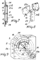
- It comprises a protective envelope 2 having features of high strength and provided with at least one aperture 3.
- a protective envelope 2 having features of high strength and provided with at least one aperture 3.
- only one aperture 3 exists for introduction and distribution of banknotes and valuables.
- the protective envelope 2 internally has a plurality of casings 4 adapted to hold banknotes or valuables 5.
- Casings 4 are disposed at consecutive positions with respect to each other, so as to form a ring, a circular ring in particular, and are subjected to two completely differentiated movements.
- a first movement extends along a ring-shaped selection path, in particular of circular form, defined by the arrangement of casings 4.
- a second movement extends in a direction transverse to the first movement and in particular at right angles to the selection path, in a radial direction.
- casings 4 are supported and guided by support and movement members 6 comprising two circular plates 7, parallel to each other, between which the casings 4 are fitted.
- plates 7 are rotatably engaged, at a rotation axis 8, within the protective envelope 2 and are moved by an electric motor 9a interlocked to electronic control means 9, known per se.
- the second movement which is radial to the rotation axis 8, is made possible because casings 4 are movably in engagement with the support and movement means 6 and because translation members 10 are present which are interlocked to the electronic control means 9 as well.
- the translation members 10 are adapted to translate at least one casing 4 towards the access opening 3 when said casing is at a predetermined transferring position 2b located along said selection path.
- the transferring position 2b is the selection path point which is the closest to the aperture 3.
- each casing 4 being able to translate between two positions: an advanced position located close to the aperture 3 and a retracted position, spaced apart from the aperture 3.
- the translation members 10 comprise guide elements 11, formed in the support and movement members 6 enabling translation of casings 4 between an advanced position projecting from the plate 7 edges, and a retracted and protected position, buried between the plates 7.
- Each casing on its opposite sides, is comprised of two flaps 12 made of resilient material and such positioned that they tend to spread apart spontaneously.
- Flaps 12 are provided with attachment areas 13 for connection to a base body 14 and wide apart portions 15 terminating with closure elements or reliefs 15a at an aperture or mouth 16.
- closure elements or reliefs 15 face each other and enable the mouth 16 to be completely occluded when the wide apart portions 15 are sufficiently close to each other.
- each flap 12 is divided into two sections, so as to emphasize the resiliency of same at each point and has a hollow 17 to facilitate gripping of the contents of a casing 4.
- flaps 12 is imposed by said guide elements 11 causing opening and closure of casings 4 simultaneously with positioning of the latter in a radial direction with respect to the rotation axis 8.
- the guide elements 11 are comprised of radial elongated holes 18 formed in the plates 7 and adapted to house pins 19 or similar elements projecting from the base bodies 14, and crosspiece-like elements 20 consisting of bars of circular section transverse to the plates 7, for example.
- the crosspiece-like elements 20 join plates 7 to each other defining said guide channels 6a therewith and are such positioned that they cause the shaped portions 15 to be forcedly moved close to each other during movement of casings 4 from said advanced to said retracted positions.
- the crosspiece-like elements 20 fix the distance between flaps 12 relative to the radial position of the casing 4 itself, and when said casings are in the retracted position they preferably impose approaching until contact of the closure reliefs 15a.
- casings 4 in the retracted position are closed and protected not only by the protective envelope 2, but also by a second envelope 2a formed of the plates 7 and crosspiece-like elements 20.
- Said translation members 10 are at least partly disposed alternately between the plates 7 or outside of the latter.
- the translation members 10 When the translation members 10 are disposed between the plates 7, they are comprised of a pusher 21, consisting of an air cylinder for example, or a screw-nut screw coupling and an end disc 21a.
- the end disc 21a is capable of pushing a base body 14 of a casing 4 from the transferring position 2b, located along said selection path, to said advanced position, close to the aperture 3.
- casings 4 Preferably in said advanced position casings 4 partly jut out of the aperture 3 and are open, as already seen, so that an easy and immediate manual access to the inside of same is enabled.
- the translation members 10 When the translation members 10 are located externally of plates 7, they have at least one axially swinging bar 23, structured for example as a movable connecting rod submitted to the action of a drive crank gear 23a or equivalent mechanishm.
- the working element 23b is provided to have, on its side facing the respective plate 7, a transverse channel 23c, extending circumferentially of axis 8 and adapted to allow passage of pins 19 driven in rotation together with plates 7, if the working element 23b is in its position of maximum approaching to axis 8, and, on the contrary, to engage said pins 19 both in a centrifugal and a centripetal direction, when the drive crank gear 23a is operated.
- Casings 4 are held within the second envelope 2a, when transferring of same towards the aperture 3 is not operated, by appropriate locking devices, preferably acting on pins 19.
- Said locking devices are comprised in particular of a fixed cam 24 extending circumferentially close to the plate 7.
- the fixed cam 24 is cut out at the transferring position 2b to enable radial advancing of pins 19 in the centrifugal direction.
- the electric motor 9a prevents rotations of the second envelope 2a which are not enabled by the electronic control means 9.
- the blind area 25 together with the occlusion plate 20a is located in the transferring position 2b when the apparatus is not used over a certain period of time, based on detections or commands by the electronic control means 9.
- freely rotating tipping over covers 26 are provided, the rotation to opening of which is directly carried out, by direct interference or thrust, by the casings 4 engaging the aperture 3.
- photoelectric cells 27 may be provided on the aperture edges, which cells are responsive to the presence of a hand and capable of locking the apparatus. Obviously, the photoelectric cells 27 are deactivated by the electronic control means 9 when the aperture 3 is engaged by a casing 4.
- the apparatus may be equipped with several sensors and control means so that all operations are made automatically.
- casings 4 are completely buried between plates 7 only when they are empty.
- the detection means 28 have sensors 28a responsive to the radial position of a casing 4 and therefore responsive to the spreading-apart degree of flaps 12, related to the amount of the banknotes therein present.
- the support and movement members 6 move the casings 4 along said selection path so as to enable passage of casings 4 one at a time by the transferring position 2b, internally of the second envelope 2a and protected.
- the translation members 10 act on each casing 4 in the transferring position 2b making it move forward until the aperture 3.
- the return devices 22 or working device 23b force the casing 4 located close to the aperture 3 to return to the inside of the second envelope 2a.
- the crosspiece-like elements 20 push the flaps 12 externally and therefore cause the wide apart portions 15 to approach each other, preferably as far as they close the casings 4.
- the electronic control means 9 records the amount of money introduced into each casing 4, in view of the following drawing operations.
- appropriate detection means may intervene to confirm and/or determine the contents of each casing 4.
- the banknotes 5 are oriented so as to engage the casing mouth 16 too, and therefore the admitted amounts force the flaps 12 to an arrangement according to a different mutual distance causing a different retraction degree of the casings between the plates 7.
- the detection means 28 measures this retraction degree and supply indications about the banknote amounts in each casing 4.
- drawing operations may be carried out: the electronic control means 9 acts on the support and movement members 6 so that, positioned each time at the transferring position 2b, is the casing 4 which, based on the recorded information, has the required money amount inside it, or an amount immediately higher.
- said casing 4 is disposed within reach of the person assigned to the drawing operations, a bank cashier for example, thanks to the translation members 10 moving the casings 4 from the transferring position 2b to the aperture 3.
- a consecutive execution of both drawing and deposit operations can be suitable also for the purpose of redepositing the change, that is the money amounts drawn in excess. If changes are not redeposited, the electronic control means 9 can carry out subsequent reduced money distributions, that is curtailed of the changes that have not been redeposited.
- the blind area 25 together with the occlusion plate 20a is provided to be disposed at the transferring position 2b, so as to achieve a further protection of the second envelope 2a at the area thereof which is the closest to the aperture 3.
- the above described apparatus of the invention puts into practice a process consisting in imparting two distinct movements to the casings internal of the protective envelope.
- the first movement consists in moving the casings along a selection path which is protected and not accessible from the protection envelope aperture.
- This first movement of the casings aims at arranging the most appropriate casing to a predetermined transferring position.
- the second movement is carried out transversely of the first one and in a direction passing by said transferring position and the protection envelope aperture.
- This second movement aims at making the casing previously brought to the transferring position easily accessible from said aperture, for a comfortable manual drawing or deposit.
- the process not only offers the facility of protecting each casing when in the transferring position, but also preferably enables it to be kept closed too, while, on the contrary, the same casing is disposed open at said aperture.
- This auxiliary movement is provided to take place simultaneously with said second movement, so that at the end-of-stroke positions each casing has already been opened or closed, without the occurence of delays.
- auxiliary movement is carried out transversely of the second movement, so as not to hinder said second movement, and consists of a spontaneous spreading apart or forced approaching of movable parts of the casings.
- the invention achieves important advantages.
- the apparatus is of simple structure and therefore of high reliability and low cost.
- the apparatus is adapted to increase the money flow rate of a bank counter for example, during both the deposit and drawing (i.e. banknote distribution) steps.
- the radial sliding of the casings enables the latter to be placed to a comfortable position for the cashier's hand.
- the safety degree is such that it is not necessary to arrange a safety closure at the access aperture 3, which makes the apparatus still simpler.
- the apparatus has a very important capacity, even when the external sizes thereof are not very large.
- This storage feature too is particularly appreciated by users, in that a prolonged work independence is allowed.
Landscapes
- Physics & Mathematics (AREA)
- General Physics & Mathematics (AREA)
- Pile Receivers (AREA)
Priority Applications (4)
| Application Number | Priority Date | Filing Date | Title |
|---|---|---|---|
| US08/580,343 US5722332A (en) | 1995-12-28 | 1995-12-28 | Apparatus and process for conducting deposit and drawing operations of banknotes and valuables |
| EP95120714A EP0783162B1 (fr) | 1995-12-28 | 1995-12-29 | Dispositif et méthode pour accepter et distribuer des billets de banque |
| DE1995607888 DE69507888T2 (de) | 1995-12-29 | 1995-12-29 | Vorrichtung und Verfahren zur Eingabe und Ausgabe von Geldscheinen und Wertpapieren |
| AT95120714T ATE176825T1 (de) | 1995-12-29 | 1995-12-29 | Vorrichtung und verfahren zur eingabe und ausgabe von geldscheinen und wertpapieren |
Applications Claiming Priority (2)
| Application Number | Priority Date | Filing Date | Title |
|---|---|---|---|
| US08/580,343 US5722332A (en) | 1995-12-28 | 1995-12-28 | Apparatus and process for conducting deposit and drawing operations of banknotes and valuables |
| EP95120714A EP0783162B1 (fr) | 1995-12-28 | 1995-12-29 | Dispositif et méthode pour accepter et distribuer des billets de banque |
Publications (2)
| Publication Number | Publication Date |
|---|---|
| EP0783162A1 true EP0783162A1 (fr) | 1997-07-09 |
| EP0783162B1 EP0783162B1 (fr) | 1999-02-17 |
Family
ID=26139005
Family Applications (1)
| Application Number | Title | Priority Date | Filing Date |
|---|---|---|---|
| EP95120714A Expired - Lifetime EP0783162B1 (fr) | 1995-12-28 | 1995-12-29 | Dispositif et méthode pour accepter et distribuer des billets de banque |
Country Status (2)
| Country | Link |
|---|---|
| US (1) | US5722332A (fr) |
| EP (1) | EP0783162B1 (fr) |
Cited By (8)
| Publication number | Priority date | Publication date | Assignee | Title |
|---|---|---|---|---|
| EP0841644A3 (fr) * | 1996-11-06 | 1999-02-03 | Air Tube Conveyors Limited | Dispositif pour le traitement de billets de banque |
| EP0892373A3 (fr) * | 1997-07-18 | 2000-08-16 | Battaglini Engineering S.n.c. di Battaglini Marco & C. | Installation à cassette pour argent liquide du type à tambour de collection de monnaie pour la protection et la distribution de billets de banque, en particulier pour banques et postes |
| GB2358509A (en) * | 2000-01-24 | 2001-07-25 | Innovative Technology Ltd | Apparatus for handling banknotes |
| WO2001095262A1 (fr) * | 2000-06-09 | 2001-12-13 | Löwen Entertainment GmbH | Dispositif destine au stockage et a la distribution de billets de banque |
| EP1102218A3 (fr) * | 1996-11-28 | 2002-05-15 | Jaime Sallen Rosello | Appareil automatique pour traiter des billets de banque |
| WO2004032068A1 (fr) * | 2002-09-02 | 2004-04-15 | Gunnebo Safe Pay Ab | Systeme de manipulation de billets de banque et/ou d'autres documents |
| DE102004030143A1 (de) * | 2004-06-22 | 2006-01-19 | Giesecke & Devrient Gmbh | Vorrichtung und Verfahren zur Bearbeitung von Banknoten |
| WO2022224112A1 (fr) | 2021-04-23 | 2022-10-27 | Nokia Technologies Oy | Pièces à géométrie héritée |
Families Citing this family (11)
| Publication number | Priority date | Publication date | Assignee | Title |
|---|---|---|---|---|
| US5918554A (en) * | 1998-03-12 | 1999-07-06 | Rassamni; Aj | Credit card security device |
| US6171167B1 (en) | 1999-02-10 | 2001-01-09 | Mag-Nif Incorporated | Currency bank |
| SE522033C2 (sv) * | 2000-12-22 | 2004-01-07 | Axlon Int Ab | Maskin och metod för utmatning av sedlar där efterfrågat belopp kan tas från en kombination av olika magasin |
| US6847861B2 (en) * | 2001-11-30 | 2005-01-25 | Mckesson Automation, Inc. | Carousel product for use in integrated restocking and dispensing system |
| US6865993B2 (en) * | 2002-04-08 | 2005-03-15 | David Warren Bartel | Safe |
| US7052097B2 (en) * | 2002-12-06 | 2006-05-30 | Mckesson Automation, Inc. | High capacity drawer with mechanical indicator for a dispensing device |
| CA2752578C (fr) * | 2003-11-26 | 2016-02-02 | Mckesson Automation Inc. | Suite integree d'instruments medicaux |
| US20080270178A1 (en) * | 2007-04-30 | 2008-10-30 | Mckesson Specialty Distribution Llc | Inventory Management System For A Medical Service Provider |
| US20110079170A1 (en) * | 2009-10-01 | 2011-04-07 | Abdullah Ali Al-Mutairi | Security system for storing firearms |
| US8393280B2 (en) | 2010-01-16 | 2013-03-12 | David W. Bartel | Lockable enclosure |
| US12543852B2 (en) * | 2021-04-05 | 2026-02-10 | Carefusion 303, Inc. | Secure receptacle with container carousel |
Citations (3)
| Publication number | Priority date | Publication date | Assignee | Title |
|---|---|---|---|---|
| DE1449020A1 (de) * | 1964-04-23 | 1969-01-16 | Carl Hermann Fa | Vorrichtung zur Ausgabe von Geldbetraegen gegen Quittung |
| DE3136610A1 (de) * | 1981-09-15 | 1983-03-31 | Professor Alfred Krauth Apparatebau GmbH & Co KG, 6930 Eberbach | Scheinspender |
| EP0604880A2 (fr) * | 1992-12-30 | 1994-07-06 | M.I.B. Elettronica S.R.L. | Dispositif et méthode pour automatiquement recevoir et distribuer des billets de banque et des objets de valeur |
Family Cites Families (18)
| Publication number | Priority date | Publication date | Assignee | Title |
|---|---|---|---|---|
| US895581A (en) * | 1907-11-06 | 1908-08-11 | Theodore W Nygreen | Safe. |
| US1004784A (en) * | 1910-05-13 | 1911-10-03 | Fairview Mfg Company | Rotary file-cabinet. |
| DE344460C (de) * | 1920-09-11 | 1921-11-22 | Frank Xavier Bergs | Kassenschrank mit zwei Saetzen von Schwingtueren |
| US1954668A (en) * | 1933-08-28 | 1934-04-10 | Charles K Ernst | Safe |
| US3784090A (en) * | 1972-07-28 | 1974-01-08 | Chubb Ind Ltd | Safe deposit apparatus |
| US4548353A (en) * | 1984-01-16 | 1985-10-22 | Robert Howard | Cash drop box having a plurality of compartments |
| DE3412424C1 (de) * | 1984-04-03 | 1985-06-27 | Nixdorf Computer Ag, 4790 Paderborn | Behaelter zur Aufnahme von Wertscheinen |
| US4884679A (en) * | 1984-04-05 | 1989-12-05 | Diebold Incorporated | Secure transport construction for banking depository devices |
| JPS60258057A (ja) * | 1984-05-31 | 1985-12-19 | Omron Tateisi Electronics Co | 紙葉類収納装置 |
| EP0182137B1 (fr) * | 1984-11-05 | 1990-02-07 | Autelca Ag | Coffre-fort pour comptoir-caisse |
| US4643107A (en) * | 1985-02-11 | 1987-02-17 | Bellsouth Corporation | Security vault |
| ATE48877T1 (de) * | 1985-12-05 | 1990-01-15 | Vidmar Ag | Sicherheitsanlage zur aufbewahrung von wertsachen. |
| US4696426A (en) * | 1986-05-30 | 1987-09-29 | Ibm Corporation | Document reading envelope depository |
| CH674396A5 (fr) * | 1988-03-10 | 1990-05-31 | Ascom Autelca Ag | |
| GB8915126D0 (en) * | 1989-06-30 | 1989-08-23 | Ncr Co | Apparatus for stacking articles in a container |
| US5172643A (en) * | 1990-07-16 | 1992-12-22 | Oki Electric Industry Co., Ltd. | Apparatus for handling strips of paper |
| DE4141530C2 (de) * | 1991-12-17 | 1993-09-30 | Ibm | Führung zur Übergabe von blattförmigen Medien |
| US5464200A (en) * | 1993-04-15 | 1995-11-07 | Ricoh Company, Ltd. | Sheet storing device with locking bins |
-
1995
- 1995-12-28 US US08/580,343 patent/US5722332A/en not_active Expired - Fee Related
- 1995-12-29 EP EP95120714A patent/EP0783162B1/fr not_active Expired - Lifetime
Patent Citations (3)
| Publication number | Priority date | Publication date | Assignee | Title |
|---|---|---|---|---|
| DE1449020A1 (de) * | 1964-04-23 | 1969-01-16 | Carl Hermann Fa | Vorrichtung zur Ausgabe von Geldbetraegen gegen Quittung |
| DE3136610A1 (de) * | 1981-09-15 | 1983-03-31 | Professor Alfred Krauth Apparatebau GmbH & Co KG, 6930 Eberbach | Scheinspender |
| EP0604880A2 (fr) * | 1992-12-30 | 1994-07-06 | M.I.B. Elettronica S.R.L. | Dispositif et méthode pour automatiquement recevoir et distribuer des billets de banque et des objets de valeur |
Non-Patent Citations (1)
| Title |
|---|
| "easily accessible bill dispense box", IBM TECHNICAL DISCLOSURE BULLETIN, vol. 31, no. 3, August 1988 (1988-08-01), ARMONK, NY, USA, pages 432 - 433, XP002004216 * |
Cited By (9)
| Publication number | Priority date | Publication date | Assignee | Title |
|---|---|---|---|---|
| EP0841644A3 (fr) * | 1996-11-06 | 1999-02-03 | Air Tube Conveyors Limited | Dispositif pour le traitement de billets de banque |
| EP1102218A3 (fr) * | 1996-11-28 | 2002-05-15 | Jaime Sallen Rosello | Appareil automatique pour traiter des billets de banque |
| EP0892373A3 (fr) * | 1997-07-18 | 2000-08-16 | Battaglini Engineering S.n.c. di Battaglini Marco & C. | Installation à cassette pour argent liquide du type à tambour de collection de monnaie pour la protection et la distribution de billets de banque, en particulier pour banques et postes |
| GB2358509A (en) * | 2000-01-24 | 2001-07-25 | Innovative Technology Ltd | Apparatus for handling banknotes |
| WO2001095262A1 (fr) * | 2000-06-09 | 2001-12-13 | Löwen Entertainment GmbH | Dispositif destine au stockage et a la distribution de billets de banque |
| WO2004032068A1 (fr) * | 2002-09-02 | 2004-04-15 | Gunnebo Safe Pay Ab | Systeme de manipulation de billets de banque et/ou d'autres documents |
| US7407157B2 (en) | 2002-09-02 | 2008-08-05 | Gunnebo Safe Pay Ab | Arrangement for handling banknotes and/or other documents |
| DE102004030143A1 (de) * | 2004-06-22 | 2006-01-19 | Giesecke & Devrient Gmbh | Vorrichtung und Verfahren zur Bearbeitung von Banknoten |
| WO2022224112A1 (fr) | 2021-04-23 | 2022-10-27 | Nokia Technologies Oy | Pièces à géométrie héritée |
Also Published As
| Publication number | Publication date |
|---|---|
| EP0783162B1 (fr) | 1999-02-17 |
| US5722332A (en) | 1998-03-03 |
Similar Documents
| Publication | Publication Date | Title |
|---|---|---|
| EP0783162B1 (fr) | Dispositif et méthode pour accepter et distribuer des billets de banque | |
| DE69014257T2 (de) | Vorrichtung zum Verpacken von Arzneimitteln. | |
| DE69009701T2 (de) | Automatische Maschine zum Umhüllen mit Plastikfolie, insbesondere geeignet zum Umhüllen von Koffern. | |
| EP3459517B1 (fr) | Cassette de médicament et appareil de conditionnement automatique de médicament associé | |
| DE60205990T2 (de) | Vorrichtung zum Kartonieren einer Spule aus drahtförmigem Wickelgut | |
| ES2200531T3 (es) | Grapadora. | |
| US4746110A (en) | Dealing port mechanism in banknote depositing and dispensing machine | |
| JPS5873502A (ja) | トレイ装入方法および装入機 | |
| US5488913A (en) | Apparatus for automatically receiving and dispensing banknotes and valuables | |
| CA1215947A (fr) | Automate vendeur a decharges laterales | |
| EP0263679B1 (fr) | Dispositif pour accepter et delivrer des feuilles | |
| EP0469637A3 (fr) | Dispositif de traitement de billets | |
| US4024966A (en) | Automatic slide magazine handler | |
| US4854247A (en) | Lock type sealed paper currency collector and security device | |
| US5611483A (en) | Coin and currency receptacle assembly for money operated machines | |
| US20240091979A1 (en) | Automatic staple loading station | |
| CA1128026A (fr) | Distributrice automatique de billets de loterie | |
| RU2118437C1 (ru) | Устройство дверцы доступа для банковского автомата, способ удержания закрытой и селективного открытия дверцы доступа банковского автомата | |
| ITBS940060A1 (it) | Distributore automatico di giornali,riviste e simili | |
| EP0344731A3 (fr) | Dispositif de guidage multicanal pour chargeur de barres de machines-outils automatiques | |
| JPS635093Y2 (fr) | ||
| CH703080B1 (de) | Sicherheitskoffer, Sicherheitssystem und Sicherheitskomplex. | |
| DE69507888T2 (de) | Vorrichtung und Verfahren zur Eingabe und Ausgabe von Geldscheinen und Wertpapieren | |
| HRP930046B1 (en) | Timely closable safety money depository | |
| KR0134308Y1 (ko) | 티켓 발매기용 지폐수납장치 |
Legal Events
| Date | Code | Title | Description |
|---|---|---|---|
| PUAI | Public reference made under article 153(3) epc to a published international application that has entered the european phase |
Free format text: ORIGINAL CODE: 0009012 |
|
| 17P | Request for examination filed |
Effective date: 19961104 |
|
| AK | Designated contracting states |
Kind code of ref document: A1 Designated state(s): AT BE CH DE FR GB LI NL |
|
| GRAG | Despatch of communication of intention to grant |
Free format text: ORIGINAL CODE: EPIDOS AGRA |
|
| GRAG | Despatch of communication of intention to grant |
Free format text: ORIGINAL CODE: EPIDOS AGRA |
|
| GRAH | Despatch of communication of intention to grant a patent |
Free format text: ORIGINAL CODE: EPIDOS IGRA |
|
| 17Q | First examination report despatched |
Effective date: 19980603 |
|
| GRAH | Despatch of communication of intention to grant a patent |
Free format text: ORIGINAL CODE: EPIDOS IGRA |
|
| GRAA | (expected) grant |
Free format text: ORIGINAL CODE: 0009210 |
|
| AK | Designated contracting states |
Kind code of ref document: B1 Designated state(s): AT BE CH DE FR GB LI NL |
|
| PG25 | Lapsed in a contracting state [announced via postgrant information from national office to epo] |
Ref country code: NL Free format text: LAPSE BECAUSE OF FAILURE TO SUBMIT A TRANSLATION OF THE DESCRIPTION OR TO PAY THE FEE WITHIN THE PRESCRIBED TIME-LIMIT Effective date: 19990217 Ref country code: LI Free format text: LAPSE BECAUSE OF FAILURE TO SUBMIT A TRANSLATION OF THE DESCRIPTION OR TO PAY THE FEE WITHIN THE PRESCRIBED TIME-LIMIT Effective date: 19990217 Ref country code: CH Free format text: LAPSE BECAUSE OF FAILURE TO SUBMIT A TRANSLATION OF THE DESCRIPTION OR TO PAY THE FEE WITHIN THE PRESCRIBED TIME-LIMIT Effective date: 19990217 Ref country code: AT Free format text: LAPSE BECAUSE OF FAILURE TO SUBMIT A TRANSLATION OF THE DESCRIPTION OR TO PAY THE FEE WITHIN THE PRESCRIBED TIME-LIMIT Effective date: 19990217 |
|
| REF | Corresponds to: |
Ref document number: 176825 Country of ref document: AT Date of ref document: 19990315 Kind code of ref document: T |
|
| REG | Reference to a national code |
Ref country code: CH Ref legal event code: EP |
|
| ET | Fr: translation filed | ||
| REF | Corresponds to: |
Ref document number: 69507888 Country of ref document: DE Date of ref document: 19990325 |
|
| NLV1 | Nl: lapsed or annulled due to failure to fulfill the requirements of art. 29p and 29m of the patents act | ||
| PLBE | No opposition filed within time limit |
Free format text: ORIGINAL CODE: 0009261 |
|
| STAA | Information on the status of an ep patent application or granted ep patent |
Free format text: STATUS: NO OPPOSITION FILED WITHIN TIME LIMIT |
|
| 26N | No opposition filed | ||
| REG | Reference to a national code |
Ref country code: GB Ref legal event code: IF02 |
|
| PGFP | Annual fee paid to national office [announced via postgrant information from national office to epo] |
Ref country code: DE Payment date: 20031218 Year of fee payment: 9 Ref country code: BE Payment date: 20031218 Year of fee payment: 9 |
|
| PGFP | Annual fee paid to national office [announced via postgrant information from national office to epo] |
Ref country code: FR Payment date: 20031222 Year of fee payment: 9 |
|
| PG25 | Lapsed in a contracting state [announced via postgrant information from national office to epo] |
Ref country code: BE Free format text: LAPSE BECAUSE OF NON-PAYMENT OF DUE FEES Effective date: 20041231 |
|
| PGFP | Annual fee paid to national office [announced via postgrant information from national office to epo] |
Ref country code: GB Payment date: 20050114 Year of fee payment: 10 |
|
| BERE | Be: lapsed |
Owner name: *M.I.B. ELETTRONICA S.R.L. Effective date: 20041231 |
|
| PG25 | Lapsed in a contracting state [announced via postgrant information from national office to epo] |
Ref country code: DE Free format text: LAPSE BECAUSE OF NON-PAYMENT OF DUE FEES Effective date: 20050701 |
|
| PG25 | Lapsed in a contracting state [announced via postgrant information from national office to epo] |
Ref country code: FR Free format text: LAPSE BECAUSE OF NON-PAYMENT OF DUE FEES Effective date: 20050831 |
|
| REG | Reference to a national code |
Ref country code: FR Ref legal event code: ST |
|
| PG25 | Lapsed in a contracting state [announced via postgrant information from national office to epo] |
Ref country code: GB Free format text: LAPSE BECAUSE OF NON-PAYMENT OF DUE FEES Effective date: 20051229 |
|
| GBPC | Gb: european patent ceased through non-payment of renewal fee |
Effective date: 20051229 |
|
| BERE | Be: lapsed |
Owner name: *M.I.B. ELETTRONICA S.R.L. Effective date: 20041231 |