EP0783185A1 - Moteur piézoélectrique à onde progressive - Google Patents
Moteur piézoélectrique à onde progressive Download PDFInfo
- Publication number
- EP0783185A1 EP0783185A1 EP96810905A EP96810905A EP0783185A1 EP 0783185 A1 EP0783185 A1 EP 0783185A1 EP 96810905 A EP96810905 A EP 96810905A EP 96810905 A EP96810905 A EP 96810905A EP 0783185 A1 EP0783185 A1 EP 0783185A1
- Authority
- EP
- European Patent Office
- Prior art keywords
- stator
- hub
- piezoelectric
- rotor
- arms
- Prior art date
- Legal status (The legal status is an assumption and is not a legal conclusion. Google has not performed a legal analysis and makes no representation as to the accuracy of the status listed.)
- Granted
Links
- 230000000750 progressive effect Effects 0.000 title claims abstract description 10
- 230000002093 peripheral effect Effects 0.000 claims description 11
- 239000006185 dispersion Substances 0.000 claims description 7
- 238000003825 pressing Methods 0.000 claims description 4
- 239000000463 material Substances 0.000 claims description 3
- 239000000919 ceramic Substances 0.000 claims description 2
- 230000010363 phase shift Effects 0.000 claims description 2
- 230000006835 compression Effects 0.000 description 3
- 238000007906 compression Methods 0.000 description 3
- 238000005553 drilling Methods 0.000 description 3
- 238000004519 manufacturing process Methods 0.000 description 2
- 238000005520 cutting process Methods 0.000 description 1
- 230000000694 effects Effects 0.000 description 1
- 238000003754 machining Methods 0.000 description 1
- 230000010355 oscillation Effects 0.000 description 1
- 230000010287 polarization Effects 0.000 description 1
Images
Classifications
-
- H—ELECTRICITY
- H02—GENERATION; CONVERSION OR DISTRIBUTION OF ELECTRIC POWER
- H02N—ELECTRIC MACHINES NOT OTHERWISE PROVIDED FOR
- H02N2/00—Electric machines in general using piezoelectric effect, electrostriction or magnetostriction
- H02N2/10—Electric machines in general using piezoelectric effect, electrostriction or magnetostriction producing rotary motion, e.g. rotary motors
- H02N2/16—Electric machines in general using piezoelectric effect, electrostriction or magnetostriction producing rotary motion, e.g. rotary motors using travelling waves, i.e. Rayleigh surface waves
- H02N2/163—Motors with ring stator
Definitions
- the subject of the invention is a traveling wave piezoelectric motor comprising at least one stator, two groups of piezoelectric elements consisting of polarized ceramic rods independent of each other, arranged perpendicular to the stator, that is to say parallel to the motor axis, distributed over the stator, in permanent contact with the stator and excited by an alternating current with a phase shift of ⁇ / 2 between the groups so as to generate on the surface of the stator a deformation in progressive wave form , and at least one disc-shaped rotor held elastically in contact with the stator for its rotational drive by the progressive wave generated on the stator.
- Such a piezoelectric motor is known from document WO 95/05 682.
- This motor comprises two disc-shaped rotors wedged on a shaft and a double stator drive system mounted between the rotors and comprising a first annular stator for driving one of the rotors and a second annular stator for driving of the second rotor.
- the stators are interconnected by double polarized piezoelectric rods, constituted by two piezoelectric rods glued in polarity opposition by one of their ends or by a single rod polarized in both directions from a single electrode, of annular shape arranged in the middle. These rods are excited by an alternating current and organized in two groups, one vibrating in phase quadrature with the other in order to produce the two standing waves necessary for the constitution of a progressive wave which, transmitted to the stators, drives the rotors in rotation.
- all the sticks of a group must vibrate in phase to participate in concert in the establishment of the progressive wave.
- Means for prestressing the piezoelectric elements are used in the piezoelectric motors described in documents FR 2 715 780 and EP 552 754 A1 for a different purpose, this goal being that the piezoelectric elements are only used in compression, these elements being more resistant to compression than to traction.
- the object of the invention is to modify the motor according to document WO 95/05 682 so that the piezoelectric rods can be compressed under a force large enough to limit the dispersion of the resonant frequencies without, however, the rotor is pressed too strongly against the stator.
- the piezoelectric motor is in the form of a wheel consisting of a peripheral ring on which the piezoelectric elements are distributed, a central hub and regularly distributed link arms between the peripheral ring and the hub and intended to transmit an axial pressure exerted on the hub to the ring and thus to the piezoelectric elements so as to limit the dispersion of the resonant frequencies of the piezoelectric elements, these arms also allowing circulation on the peripheral ring of a traveling wave, the axial pressure applied by means of pressure means to the hub to compress the piezoelectric elements being independent of the means keeping the rotor resiliently in contact against the stator.
- the stator thus produced makes it possible to compress the rods under a force independent of that applied to the rotor. It therefore makes it possible to compress them with a sufficiently large force to limit the dispersion of the resonance frequencies.
- a motor produced with the stator according to the invention has a quality factor, also called overvoltage factor, five times greater than that of a motor produced according to the prior art.
- the parts of the engine, in particular the stator are simple to produce industrially.
- the stator can be simplified to the extreme, for greater ease of manufacture during industrialization, by making the holes by drilling and cutting, the articulation radii then being formed by the material between the holes.
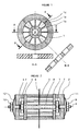
- Figure 1 shows the stator according to the invention in three different views: a top view and two cross sections.
- FIG. 2 shows an axial sectional view of an embodiment of the piezoelectric motor according to the invention.
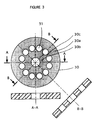
- FIG. 3 represents an alternative embodiment of the stator of FIG. 1.
- the stator 1 shown in Figure 1 consists of a peripheral ring 1a and a hub 1b connected to each other by radial arms 1c distributed uniformly over the entire periphery. These arms lc have a width which is only a fraction of their thickness. In the example shown, the width / thickness ratio is approximately 1/5.
- the stator is in one piece.
- the spokes 1c of the stator 1 can transmit a stress applied to the hub 1b to the peripheral ring 1a. Since the spokes are free to be twisted in their smallest thickness, they allow the propagation of a progressive flexion wave in the peripheral ring and therefore do not harm the oscillations of the contact surface formed by the ring 1a.
- the arms 1c could be formed by simple drilling. In this case, the holes separating the arms are round and it is only in their central region that the arms have a width which is only a fraction of their thickness.
- the motor partially represented in FIG. 2 comprises two rotors 2, 3 wedged on a shaft 4 and a double stator drive system mounted between the rotors 2, 3 and comprising two stators 1 such as that represented in FIG. 1, the one being intended for driving the rotor 2 and the other for driving the rotor 3.
- the peripheral rings of the stators 1 are connected together by two groups of six piezoelectric rods 5 with double polarization, as in the motor according to document WO 95/05682. These rods are polarized in both directions from a single electrode 6 of annular shape arranged in their middle and arranged parallel to the motor shaft 4.
- the rods 5 are compressed between the stators 1 by means of nuts 7 mounted on a threaded tube 8 passing through the hubs of the stators, these nuts 7 pressing the stators 1 towards one another and therefore compressing the piezoelectric rods 5
- the threaded tube 8 is crossed coaxially by the shaft 4 of the rotors 2, 3.
- the tube 8 and the shaft 4 are free to rotate relative to one another.
- the rotors 2, 3 are respectively pressed elastically against their stator 1 by means of a nut 9, 10 screwed onto the shaft 4 and pressing an elastic washer 11, 12 against the rotors 2, 3.
- the force intended to compress the piezoelectric elements and that intended to press the rotor against the stator can thus be applied independently of one another.
- the radial arms 30c connecting the hub 30b to the ring 30a are formed by the material remaining between circular holes 31 formed by drilling.
- the arms 30c are substantially shorter than the arms lc in FIG. 1, which has the advantageous effect of raising their resonant frequency well beyond the working frequencies.
- the means for applying force to the rotor and the rods may be different from those shown, these having been simplified as much as possible for the sake of convenience of explanation.
Landscapes
- General Electrical Machinery Utilizing Piezoelectricity, Electrostriction Or Magnetostriction (AREA)
- Power Steering Mechanism (AREA)
Abstract
Description
- L'invention a pour objet un moteur piézoélectrique à onde progressive comprenant au moins un stator, deux groupes d'éléments piézoélectriques constitués de bâtonnets de céramique polarisés indépendants les uns des autres, disposés perpendiculairement au stator, c'est-à-dire parallèlement à l'axe du moteur, répartis sur le stator, en contact permanent avec le stator et excités par un courant alternatif avec un déphasage de π/2 entre les groupes de manière à engendrer à la surface du stator une déformation en forme d'onde progressive, et au moins un rotor en forme de disque maintenu élastiquement en contact avec le stator pour son entraînement en rotation par l'onde progressive engendrée sur le stator.
- Un tel moteur piézoélectrique est connu du document WO 95/05 682.
- Ce moteur comprend deux rotors en forme de disques calés sur un arbre et un système d'entraînement à double stator monté entre les rotors et comprenant un premier stator annulaire pour l'entraînement d'un des rotors et un deuxième stator annulaire pour l'entraînement du deuxième rotor. Les stators sont reliés entre eux par des bâtonnets piézoélectriques à double polarisation, constitués par deux bâtonnets piézoélectriques collés en opposition de polarité par une de leurs extrémités ou par un bâtonnet unique polarisé dans les deux directions à partir d'une électrode unique, de forme annulaire disposée en son milieu. Ces bâtonnets sont excités par un courant alternatif et organisés en deux groupes, l'un vibrant en quadrature de phase avec l'autre afin de produire les deux ondes stationnaires nécessaires à la constitution d'une onde progressive qui, transmise aux stators, entraîne les rotors en rotation.
- Une dispersion de fréquence de résonance des bâtonnets de quelques hertz, due à une différence de longueur des bâtonnets, entraîne une dispersion de phase importante entre les ondes engendrées. Or, tous les bâtonnets d'un groupe doivent vibrer en phase pour participer de concert à l'établissement de l'onde progressive.
- Les solutions connues à ce problème sont d'appairer les bâtonnets, ce qui est coûteux et inadapté à la grande série ou de les tronçonner ou ajuster avec une grande précision, ce qui entraîne également un surcoût. Ces deux moyens ont, de plus, leur limite dans la précision d'usinage.
- Une autre solution serait de comprimer les bâtonnets. On a, en effet, constaté que leur compression permet de limiter considérablement la dispersion des fréquences de résonance.
- Dans le moteur selon le document WO 95/05 682, la force appliquée sur les bâtonnets est cependant liée directement à celle appliquée au rotor. Or, la force qui doit être appliquée entre rotor et stator est environ dix fois moins importante que celle nécessaire pour comprimer efficacement les bâtonnets. Il faut donc compromettre sur ces deux forces qui ont des exigences sensiblement différentes.
- Des moyens de précontrainte des éléments piézoélectriques sont utilisés dans les moteurs piézoélectriques décrits dans les documents FR 2 715 780 et EP 552 754 A1 dans un but différent, ce but étant que les éléments piézoélectriques soient uniquement utilisés en compression, ces éléments étant plus résistants à la compression qu'à la traction.
- Ces moyens de précontrainte ne sont cependant pas applicables de manière simple au moteur du document WO 95/05 682.
- Aussi, le but de l'invention est de modifier le moteur selon le document WO 95/05 682 de manière à ce que les bâtonnets piézoélectriques puissent être comprimés sous une force suffisamment importante pour limiter la dispersion des fréquences de résonance sans pour autant que le rotor soit appuyé trop fortement contre le stator.
- Ce but est atteint par le moteur piézoélectrique selon l'invention, caractérisé en ce que le stator est en forme de roue constituée d'un anneau périphérique sur lequel sont répartis les éléments piézoélectriques, d'un moyeu central et de bras de liaison répartis régulièrement entre l'anneau périphérique et le moyeu et destinés à transmettre une pression axiale exercée au moyeu à l'anneau et ainsi aux éléments piézoélectriques de manière à limiter la dispersion des fréquences de résonance des éléments piézoélectriques, ces bras permettant par ailleurs la circulation sur l'anneau périphérique d'une onde progressive, la pression axiale appliquée au moyen de moyens de pression au moyeu pour comprimer les éléments piézoélectiques étant indépendante des moyens maintenant le rotor élastiquement en contact contre le stator.
- Le stator ainsi réalisé permet de comprimer les bâtonnets sous une force indépendante de celle appliquée au rotor. Il permet donc de les comprimer avec une force suffisamment importante pour limiter la dispersion des fréquences de résonance.
- Un moteur réalisé avec le stator selon l'invention possède un facteur de qualité, aussi appelé facteur de surtension, cinq fois supérieur à celui d'un moteur réalisé selon l'art antérieur.
- De plus, les pièces du moteur, en particulier le stator, sont simples à réaliser industriellement.
- Le stator peut être simplifié à l'extrême, pour une plus grande facilité de fabrication lors de l'industrialisation, en réalisant les trous par perçage et découpage, les rayons d'articulation étant alors formés par la matière entre les trous.
- Le dessin annexé représente une forme d'exécution de l'invention.
- La figure 1 représente le stator selon l'invention selon trois vues différentes : une vue de dessus et deux coupes transversales.
- La figure 2 représente une vue en coupe axiale d'une forme d'exécution du moteur piézoélectrique selon l'invention.
- La figure 3 représente une variante d'exécution du stator de la figure 1.
- Le stator 1 représenté en figure 1 est constitué d'un anneau périphérique 1a et d'un moyeu 1b reliés l'un à l'autre par des bras radiaux 1c répartis uniformément sur toute la périphérie. Ces bras lc ont une largeur qui n'est qu'une fraction de leur épaisseur. Dans l'exemple représenté, le rapport largeur/épaisseur est d'environ 1/5. Le stator est en une seule pièce.
- Sollicités dans l'axe de leur plus grande épaisseur, les rayons 1c du stator 1 peuvent transmettre une contrainte appliquée au moyeu 1b à l'anneau périphérique 1a. Les rayons ayant toute liberté d'être torsadés dans leur plus petite épaisseur, ils permettent la propagation d'une onde progressive de flexion dans l'anneau périphérique et ne nuisent donc pas aux oscillations de la surface de contact formée par l'anneau 1a.
- Les bras 1c pourraient être formés par simple perçage. Dans ce cas, les trous séparant les bras sont ronds et ce n'est que dans leur zone médiane que les bras présentent une largeur qui n'est qu'une fraction de leur épaisseur.
- Le moteur représenté en partie en figure 2 comprend deux rotors 2, 3 calés sur un arbre 4 et un système d'entraînement à double stator monté entre les rotors 2, 3 et comprenant deux stators 1 tel que celui représenté en figure 1, l'un étant destiné à l'entraînement du rotor 2 et l'autre à l'entraînement du rotor 3. Les anneaux périphériques des stators 1 sont reliés entre eux par deux groupes de six bâtonnets piézoélectriques 5 à double polarisation, comme dans le moteur selon le document WO 95/05682. Ces bâtonnets sont polarisés dans les deux directions à partir d'une électrode unique 6 de forme annulaire disposée en leur milieu et disposés parallèlement à l'arbre 4 du moteur. Les bâtonnets 5 sont comprimés entre les stators 1 au moyen d'écrous 7 montés sur un tube fileté 8 traversant les moyeux des stators, ces écrous 7 pressant les stators 1 en direction l'un de l'autre et donc comprimant les bâtonnets piézoélectriques 5. Le tube fileté 8 est traversé coaxialement par l'arbre 4 des rotors 2, 3. Le tube 8 et l'arbre 4 sont libres en rotation l'un par rapport à l'autre. Les rotors 2, 3 sont respectivement appuyés élastiquement contre leur stator 1 au moyen d'un écrou 9, 10 vissé sur l'arbre 4 et appuyant une rondelle élastique 11, 12 contre les rotors 2, 3.
- Par des moyens relativement simples, la force destinée à comprimer les éléments piézoélectriques et celle destinée à appuyer le rotor contre le stator peuvent ainsi être appliquées indépendamment l'une de l'autre.
- Selon une variante d'exécution du stator, telle que représentée à la figure 3, les bras radiaux 30c reliant le moyeu 30b à l'anneau 30a sont formés par la matière subsistant entre des trous circulaires 31 formés par perçage. Les bras 30c sont sensiblement plus courts que les bras lc de la figure 1, ce qui a pour effet avantageux d'élever leur fréquence de résonance bien au delà des fréquences de travail.
- La forme d'exécution décrite dans les figures 1, 2 et 3 n'est pas limitative de l'étendue de l'invention.
- Les moyens d'application de force sur le rotor et les bâtonnets peuvent être différents de ceux représentés, ceux-ci ayant été simplifiés au maximum pour raison de commodité d'explication.
Claims (5)
- Moteur piézoélectrique à onde progressive comprenant au moins un stator (1), deux groupes d'éléments piézoélectriques constitués de bâtonnets de céramique (5) polarisés indépendants les uns des autres, disposés perpendiculairement au stator (1), c'est-à-dire parallèlement à l'axe du moteur, répartis sur le stator (1), en contact permanent avec le stator (1) et excités par un courant alternatif avec un déphasage de π/2 entre les groupes de manière à engendrer à la surface du stator (1) une déformation en forme d'onde progressive, et au moins un rotor (2, 3) en forme de disque maintenu élastiquement en contact avec le stator (1) pour son entraînement en rotation par l'onde progressive engendrée sur le stator, caractérisé en ce que le stator (1) est en forme de roue constituée d'un anneau périphérique (1a) sur lequel sont répartis les éléments piézoélectriques, d'un moyeu central et de bras de liaison (1c) répartis régulièrement entre l'anneau périphérique et le moyeu (1b) et destinés à transmettre à l'anneau (1a) une pression axiale exercée au moyeu (1b) et ainsi aux éléments piézoélectriques (5), de manière à limiter la dispersion de fréquence de résonance des éléments piézoélectriques (5), ces bras (1c) permettant par ailleurs la circulation sur l'anneau périphérique (1a) d'une onde progressive, la pression axiale appliquée au moyen de moyens de pression (7) au moyeu (1b) pour comprimer les éléments piézoélectiques étant indépendante des moyens (9, 10, 11, 12) maintenant le rotor (2, 3) élastiquement en contact contre le stator (1).
- Moteur piézoélectrique selon la revendication 1, caractérisé en ce que les bras de liaison (1c) ont, au moins dans leur zone médiane, une largeur inférieure à leur épaisseur de manière à pouvoir transmettre une contrainte appliquée au moyeu (1b) à l'anneau périphérique (1a) et à permettre la propagation d'une onde progressive dans l'anneau périphérique (1a).
- Moteur piézoélectrique selon la revendication 2, caractérisé en ce que lesdits bras (30c) sont formés par la matière subsistant entre des trous circulaires (31) répartis circulairement sur un disque.
- Moteur piézoélectrique selon l'une des revendications 1 à 3, caractérisé en ce qu'un tube creux (8) traverse le moyeu (1b) axialement, que les moyens de pression (7) permettant l'application d'une pression axiale au moyeu (1b) en direction des bâtonnets (5) sont constitués par un élément (7) amovible solidaire de ce tube (8) et appuyant sur le moyeu (1b) et en ce que le rotor (2, 3) est calé sur un arbre (4) traversant le tube (8) axialement et libre en rotation par rapport à ce tube (8), les moyens (9, 10, 11, 12) maintenant le rotor élastiquement contre le stator (1) étant constitués par un élément (9, 10) amovible solidaire de l'arbre (4) et appuyant sur un élément élastique (11, 12) transmettant la pression au rotor (2, 3).
- Moteur piézoélectrique selon la revendication (4), caractérisé en ce que les éléments amovibles (7, 9, 10) sont des écrous respectivement vissés sur le tube (8) et sur l'arbre du rotor (4).
Applications Claiming Priority (2)
| Application Number | Priority Date | Filing Date | Title |
|---|---|---|---|
| FR9600061A FR2743457B1 (fr) | 1996-01-04 | 1996-01-04 | Moteur piezoelectrique a onde progressive |
| FR9600061 | 1996-01-04 |
Publications (2)
| Publication Number | Publication Date |
|---|---|
| EP0783185A1 true EP0783185A1 (fr) | 1997-07-09 |
| EP0783185B1 EP0783185B1 (fr) | 2000-04-12 |
Family
ID=9487894
Family Applications (1)
| Application Number | Title | Priority Date | Filing Date |
|---|---|---|---|
| EP96810905A Expired - Lifetime EP0783185B1 (fr) | 1996-01-04 | 1996-12-24 | Moteur piézoélectrique à onde progressive |
Country Status (7)
| Country | Link |
|---|---|
| US (1) | US5726519A (fr) |
| EP (1) | EP0783185B1 (fr) |
| JP (1) | JPH09205787A (fr) |
| AT (1) | ATE191811T1 (fr) |
| DE (1) | DE69607733T2 (fr) |
| ES (1) | ES2110937T1 (fr) |
| FR (1) | FR2743457B1 (fr) |
Families Citing this family (11)
| Publication number | Priority date | Publication date | Assignee | Title |
|---|---|---|---|---|
| JPH1094274A (ja) * | 1996-09-11 | 1998-04-10 | Canon Inc | 振動型駆動装置およびこれを備えた装置 |
| FR2773924B1 (fr) * | 1998-01-16 | 2000-03-17 | Figest Bv | Moteur piezo-electrique a onde progressive |
| FR2799319B1 (fr) * | 1999-10-05 | 2003-12-12 | Metabole Dev Et Conseil | Moteur ultrasonique a onde progressive |
| DE112006000372T5 (de) * | 2005-02-19 | 2008-01-10 | General Motors Global Technology Operations, Inc., Detroit | Umkonfigurierbare Strukturen auf der Basis von Knoten aus aktivem Material |
| JP4756916B2 (ja) * | 2005-05-31 | 2011-08-24 | キヤノン株式会社 | 振動波モータ |
| US8113864B2 (en) * | 2010-05-13 | 2012-02-14 | Delta Electronics, Inc. | Quick-detachable terminal seat and programmable logic controller having the same |
| CN104410324B (zh) * | 2014-11-27 | 2017-06-30 | 南京航空航天大学 | 一种微型旋转直线行波压电电机 |
| US9759270B2 (en) * | 2015-04-15 | 2017-09-12 | Genesis Robotics Llp | Wave actuator |
| TWI647901B (zh) * | 2017-06-22 | 2019-01-11 | 中原大學 | 線性壓電馬達及其滑台傳動系統 |
| CN110677072B (zh) * | 2019-10-23 | 2020-09-15 | 维沃移动通信有限公司 | 电子设备 |
| CN113162466B (zh) * | 2021-01-25 | 2023-01-06 | 南京航空航天大学 | 一种贴片式双定子旋转型超声电机及控制方法 |
Citations (4)
| Publication number | Priority date | Publication date | Assignee | Title |
|---|---|---|---|---|
| EP0552754A1 (fr) | 1992-01-23 | 1993-07-28 | Canon Kabushiki Kaisha | Moteur entrainé par des vibrations |
| US5363006A (en) * | 1991-11-27 | 1994-11-08 | Asmo Co., Ltd. | Stator for ultrasonic motor and method for manufacturing the same |
| WO1995005682A1 (fr) | 1993-08-18 | 1995-02-23 | Figest B.V. | Moteur piezo-electrique a onde progressive |
| FR2715780A1 (fr) | 1994-02-01 | 1995-08-04 | Imra Europe Sa | Stator de moteur rotatif piézoélectrique et moteur rotatif piézoélectrique comportant un tel stator. |
Family Cites Families (2)
| Publication number | Priority date | Publication date | Assignee | Title |
|---|---|---|---|---|
| US5215257A (en) * | 1992-07-16 | 1993-06-01 | United Technologies Corporation | Divergent seal arrangement for a convergent/divergent nozzle |
| JP3059031B2 (ja) * | 1993-09-22 | 2000-07-04 | キヤノン株式会社 | 振動波駆動装置及び振動波駆動装置を備えた装置 |
-
1996
- 1996-01-04 FR FR9600061A patent/FR2743457B1/fr not_active Expired - Fee Related
- 1996-12-19 US US08/770,134 patent/US5726519A/en not_active Expired - Fee Related
- 1996-12-24 ES ES96810905T patent/ES2110937T1/es active Pending
- 1996-12-24 EP EP96810905A patent/EP0783185B1/fr not_active Expired - Lifetime
- 1996-12-24 AT AT96810905T patent/ATE191811T1/de not_active IP Right Cessation
- 1996-12-24 DE DE69607733T patent/DE69607733T2/de not_active Expired - Fee Related
-
1997
- 1997-01-06 JP JP9000030A patent/JPH09205787A/ja active Pending
Patent Citations (5)
| Publication number | Priority date | Publication date | Assignee | Title |
|---|---|---|---|---|
| US5363006A (en) * | 1991-11-27 | 1994-11-08 | Asmo Co., Ltd. | Stator for ultrasonic motor and method for manufacturing the same |
| EP0552754A1 (fr) | 1992-01-23 | 1993-07-28 | Canon Kabushiki Kaisha | Moteur entrainé par des vibrations |
| WO1995005682A1 (fr) | 1993-08-18 | 1995-02-23 | Figest B.V. | Moteur piezo-electrique a onde progressive |
| FR2715780A1 (fr) | 1994-02-01 | 1995-08-04 | Imra Europe Sa | Stator de moteur rotatif piézoélectrique et moteur rotatif piézoélectrique comportant un tel stator. |
| EP0669662A1 (fr) * | 1994-02-01 | 1995-08-30 | Imra Europe S.A. | Moteur rotatif piézoélectrique |
Also Published As
| Publication number | Publication date |
|---|---|
| US5726519A (en) | 1998-03-10 |
| DE69607733D1 (de) | 2000-05-18 |
| JPH09205787A (ja) | 1997-08-05 |
| FR2743457B1 (fr) | 1998-03-06 |
| DE69607733T2 (de) | 2000-08-31 |
| EP0783185B1 (fr) | 2000-04-12 |
| ATE191811T1 (de) | 2000-04-15 |
| ES2110937T1 (es) | 1998-03-01 |
| FR2743457A1 (fr) | 1997-07-11 |
Similar Documents
| Publication | Publication Date | Title |
|---|---|---|
| EP0783185B1 (fr) | Moteur piézoélectrique à onde progressive | |
| CA2981545C (fr) | Troncon de mat d'eolienne, mat d'eolienne et procede d'assemblage | |
| FR2922693A1 (fr) | Rotor de machine electrique tournante et son procede de fabrication. | |
| FR2943862A1 (fr) | Stator pour machine rotative electrique | |
| FR2748358A1 (fr) | Machine electrique comprenant un stator et un rotor a poles divises en une pluralite de sections longitudinales | |
| FR2852369A1 (fr) | Systeme de bride d'accouplement pour arbre creux | |
| EP2615726A1 (fr) | Rotor, procédé de fabrication et machine électrique correspondants | |
| CA2434511C (fr) | Systeme de freinage pour roues d'aeronef | |
| FR2559342A1 (fr) | Transmission pour tondeuse a gazon | |
| FR2917332A1 (fr) | Roue comprenant une jante, un moyeu, et un dispositif de raccordement de la jante au moyeu | |
| EP3048703B1 (fr) | Masse magnétique pour rotor, rotor, machine électrique et procédé de fabrication de cette masse | |
| EP0784368B1 (fr) | Rotor magnétoélectrique à griffes | |
| EP0538088B1 (fr) | Rotor multipale, notamment pour hélice arrière anticouple d'hélicoptère et procédé pour sa réalisation | |
| FR2544815A1 (fr) | Joint de transmission en croix pour arbre articule | |
| EP3767397B1 (fr) | Mouvement horloger comprenant un element tournant muni d'une structure aimantee ayant une configuration periodique | |
| CA2160222C (fr) | Perfectionnements aux tamis d'epuration, notamment pour la pate a papier | |
| EP0714559B1 (fr) | Moteur piezo-electrique a onde progressive | |
| FR2928637A1 (fr) | Structure de treuil | |
| EP0793282B1 (fr) | Moteur piézoélectrique à onde progressive | |
| EP0930660B1 (fr) | Moteur pièzo-électrique à onde progressive | |
| EP2269431A1 (fr) | Rouleau à pneumatiques semi-creux, notamment pour machines agricoles | |
| FR2670334A1 (fr) | Collecteur moule pour machine tournante electrique du type tambour. | |
| FR2844114A1 (fr) | Moteur electroactif monophase | |
| FR2692327A1 (fr) | Arbre rotatif à structure tubulaire renforcée. | |
| EP0333539A1 (fr) | Moteur pas à pas linéaire débrayable à rotor recentré |
Legal Events
| Date | Code | Title | Description |
|---|---|---|---|
| PUAI | Public reference made under article 153(3) epc to a published international application that has entered the european phase |
Free format text: ORIGINAL CODE: 0009012 |
|
| AK | Designated contracting states |
Kind code of ref document: A1 Designated state(s): AT BE CH DE ES GB IT LI NL SE |
|
| REG | Reference to a national code |
Ref country code: ES Ref legal event code: BA2A Ref document number: 2110937 Country of ref document: ES Kind code of ref document: T1 |
|
| 17P | Request for examination filed |
Effective date: 19980107 |
|
| RAP1 | Party data changed (applicant data changed or rights of an application transferred) |
Owner name: FIGEST B.V. |
|
| GRAG | Despatch of communication of intention to grant |
Free format text: ORIGINAL CODE: EPIDOS AGRA |
|
| 17Q | First examination report despatched |
Effective date: 19990707 |
|
| GRAG | Despatch of communication of intention to grant |
Free format text: ORIGINAL CODE: EPIDOS AGRA |
|
| GRAH | Despatch of communication of intention to grant a patent |
Free format text: ORIGINAL CODE: EPIDOS IGRA |
|
| GRAH | Despatch of communication of intention to grant a patent |
Free format text: ORIGINAL CODE: EPIDOS IGRA |
|
| GRAA | (expected) grant |
Free format text: ORIGINAL CODE: 0009210 |
|
| AK | Designated contracting states |
Kind code of ref document: B1 Designated state(s): AT BE CH DE ES GB IT LI NL SE |
|
| PG25 | Lapsed in a contracting state [announced via postgrant information from national office to epo] |
Ref country code: NL Free format text: LAPSE BECAUSE OF FAILURE TO SUBMIT A TRANSLATION OF THE DESCRIPTION OR TO PAY THE FEE WITHIN THE PRESCRIBED TIME-LIMIT Effective date: 20000412 Ref country code: AT Free format text: LAPSE BECAUSE OF FAILURE TO SUBMIT A TRANSLATION OF THE DESCRIPTION OR TO PAY THE FEE WITHIN THE PRESCRIBED TIME-LIMIT Effective date: 20000412 |
|
| REF | Corresponds to: |
Ref document number: 191811 Country of ref document: AT Date of ref document: 20000415 Kind code of ref document: T |
|
| REG | Reference to a national code |
Ref country code: CH Ref legal event code: EP |
|
| REG | Reference to a national code |
Ref country code: CH Ref legal event code: NV Representative=s name: BUGNION S.A. |
|
| REF | Corresponds to: |
Ref document number: 69607733 Country of ref document: DE Date of ref document: 20000518 |
|
| ITF | It: translation for a ep patent filed | ||
| GBT | Gb: translation of ep patent filed (gb section 77(6)(a)/1977) |
Effective date: 20000519 |
|
| PG25 | Lapsed in a contracting state [announced via postgrant information from national office to epo] |
Ref country code: SE Free format text: LAPSE BECAUSE OF FAILURE TO SUBMIT A TRANSLATION OF THE DESCRIPTION OR TO PAY THE FEE WITHIN THE PRESCRIBED TIME-LIMIT Effective date: 20000712 |
|
| NLV1 | Nl: lapsed or annulled due to failure to fulfill the requirements of art. 29p and 29m of the patents act | ||
| PG25 | Lapsed in a contracting state [announced via postgrant information from national office to epo] |
Ref country code: ES Free format text: LAPSE BECAUSE OF FAILURE TO SUBMIT A TRANSLATION OF THE DESCRIPTION OR TO PAY THE FEE WITHIN THE PRESCRIBED TIME-LIMIT Effective date: 20001018 |
|
| PGFP | Annual fee paid to national office [announced via postgrant information from national office to epo] |
Ref country code: DE Payment date: 20001125 Year of fee payment: 5 |
|
| PGFP | Annual fee paid to national office [announced via postgrant information from national office to epo] |
Ref country code: CH Payment date: 20001130 Year of fee payment: 5 |
|
| PGFP | Annual fee paid to national office [announced via postgrant information from national office to epo] |
Ref country code: GB Payment date: 20001220 Year of fee payment: 5 |
|
| PG25 | Lapsed in a contracting state [announced via postgrant information from national office to epo] |
Ref country code: BE Free format text: LAPSE BECAUSE OF NON-PAYMENT OF DUE FEES Effective date: 20001231 |
|
| PLBE | No opposition filed within time limit |
Free format text: ORIGINAL CODE: 0009261 |
|
| STAA | Information on the status of an ep patent application or granted ep patent |
Free format text: STATUS: NO OPPOSITION FILED WITHIN TIME LIMIT |
|
| 26N | No opposition filed | ||
| BERE | Be: lapsed |
Owner name: FIGEST B.V. Effective date: 20001231 |
|
| PG25 | Lapsed in a contracting state [announced via postgrant information from national office to epo] |
Ref country code: GB Free format text: LAPSE BECAUSE OF NON-PAYMENT OF DUE FEES Effective date: 20011224 |
|
| PG25 | Lapsed in a contracting state [announced via postgrant information from national office to epo] |
Ref country code: LI Free format text: LAPSE BECAUSE OF NON-PAYMENT OF DUE FEES Effective date: 20011231 Ref country code: CH Free format text: LAPSE BECAUSE OF NON-PAYMENT OF DUE FEES Effective date: 20011231 |
|
| REG | Reference to a national code |
Ref country code: GB Ref legal event code: IF02 |
|
| PG25 | Lapsed in a contracting state [announced via postgrant information from national office to epo] |
Ref country code: DE Free format text: LAPSE BECAUSE OF NON-PAYMENT OF DUE FEES Effective date: 20020702 |
|
| GBPC | Gb: european patent ceased through non-payment of renewal fee |
Effective date: 20011224 |
|
| REG | Reference to a national code |
Ref country code: CH Ref legal event code: PL |
|
| PG25 | Lapsed in a contracting state [announced via postgrant information from national office to epo] |
Ref country code: IT Free format text: LAPSE BECAUSE OF NON-PAYMENT OF DUE FEES;WARNING: LAPSES OF ITALIAN PATENTS WITH EFFECTIVE DATE BEFORE 2007 MAY HAVE OCCURRED AT ANY TIME BEFORE 2007. THE CORRECT EFFECTIVE DATE MAY BE DIFFERENT FROM THE ONE RECORDED. Effective date: 20051224 |