EP0783185B1 - Moteur piézoélectrique à onde progressive - Google Patents
Moteur piézoélectrique à onde progressive Download PDFInfo
- Publication number
- EP0783185B1 EP0783185B1 EP96810905A EP96810905A EP0783185B1 EP 0783185 B1 EP0783185 B1 EP 0783185B1 EP 96810905 A EP96810905 A EP 96810905A EP 96810905 A EP96810905 A EP 96810905A EP 0783185 B1 EP0783185 B1 EP 0783185B1
- Authority
- EP
- European Patent Office
- Prior art keywords
- stator
- hub
- rotor
- piezoelectric
- arms
- Prior art date
- Legal status (The legal status is an assumption and is not a legal conclusion. Google has not performed a legal analysis and makes no representation as to the accuracy of the status listed.)
- Expired - Lifetime
Links
- 230000000750 progressive effect Effects 0.000 title abstract description 6
- 230000002093 peripheral effect Effects 0.000 claims description 11
- 239000000463 material Substances 0.000 claims description 3
- 239000000919 ceramic Substances 0.000 claims description 2
- 230000010363 phase shift Effects 0.000 claims description 2
- 239000007787 solid Substances 0.000 claims 2
- 230000000717 retained effect Effects 0.000 claims 1
- 239000006185 dispersion Substances 0.000 description 6
- 230000006835 compression Effects 0.000 description 3
- 238000007906 compression Methods 0.000 description 3
- 238000005553 drilling Methods 0.000 description 3
- 230000010287 polarization Effects 0.000 description 2
- 238000003825 pressing Methods 0.000 description 2
- 238000005452 bending Methods 0.000 description 1
- 238000005520 cutting process Methods 0.000 description 1
- 230000000694 effects Effects 0.000 description 1
- 238000003754 machining Methods 0.000 description 1
- 238000004519 manufacturing process Methods 0.000 description 1
- 230000010355 oscillation Effects 0.000 description 1
Images

Classifications
-
- H—ELECTRICITY
- H02—GENERATION; CONVERSION OR DISTRIBUTION OF ELECTRIC POWER
- H02N—ELECTRIC MACHINES NOT OTHERWISE PROVIDED FOR
- H02N2/00—Electric machines in general using piezoelectric effect, electrostriction or magnetostriction
- H02N2/10—Electric machines in general using piezoelectric effect, electrostriction or magnetostriction producing rotary motion, e.g. rotary motors
- H02N2/16—Electric machines in general using piezoelectric effect, electrostriction or magnetostriction producing rotary motion, e.g. rotary motors using travelling waves, i.e. Rayleigh surface waves
- H02N2/163—Motors with ring stator
Definitions
- the subject of the invention is a piezoelectric motor with traveling wave comprising at least one stator, two groups of piezoelectric elements consisting of independent polarized ceramic sticks others, arranged perpendicular to the stator, that is to say parallel to the axis of the engine, distributed on the stator, in permanent contact with the stator and excited by an alternating current with a phase shift of ⁇ / 2 between the groups so as to generate stator surface waveform deformation progressive, and at least one disc-shaped rotor kept elastically in contact with the stator to its rotational drive by the progressive wave generated on the stator.
- Such a piezoelectric motor is known from the document WO 95/05 682.
- This motor includes two disc-shaped rotors wedged on a tree and a drive system to double stator mounted between the rotors and comprising a first annular stator for driving one of the rotors and a second annular stator for the drive of the second rotor.
- the stators are interconnected by piezoelectric rods to double polarization, made up of two rods piezoelectric bonded in opposite polarity by one of their ends or by a single stick polarized in both directions from a single electrode, annular in shape arranged in sound middle. These rods are excited by a current alternative and organized in two groups, one vibrant in phase quadrature with each other in order to produce the two standing waves necessary for the constitution of a progressive wave which, transmitted to stators, drives the rotors in rotation.
- Means of prestressing the elements piezoelectric are used in motors piezoelectric described in documents FR 2 715 780 and EP 552 754 A1 for a different purpose, this purpose being that the piezoelectric elements are only used in compression, these elements being more resistant to compression than to traction.
- prestressing means are however not easily applicable to the WO document engine 95/05 682.
- the object of the invention is to modify the engine according to document WO 95/05 682 so that the piezoelectric sticks can be compressed under a force large enough to limit the dispersion of resonant frequencies without the rotor is pressed too strongly against the stator.
- the piezoelectric motor characterized in that the stator is in wheel shape consisting of a peripheral ring on which are distributed the piezoelectric elements, a central hub and distributed link arms evenly between the peripheral ring and the hub and intended to transmit an axial pressure exerted to the hub to the ring and thus to the elements piezoelectric so as to limit the dispersion of resonance frequencies of piezoelectric elements, these arms also allowing circulation on the peripheral ring of a traveling wave, the axial pressure applied by means of pressure at the hub to compress the elements piezoelectric being independent of means keeping the rotor resiliently in contact with the stator.
- stator thus produced makes it possible to compress the sticks under a force independent of that applied to the rotor. It therefore allows them to be compressed with enough force to limit the dispersion of resonance frequencies.
- a motor produced with the stator according to the invention has a quality factor, also called a overvoltage, five times that of a motor made according to the prior art.
- the stator can be simplified to the extreme, for a greater ease of manufacture during industrialization, by making the holes by drilling and cutting, the articulation radii then being formed by the material between the holes.
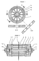
- Figure 1 shows the stator according to the invention according to three different views: a top view and two cross sections.
- Figure 2 shows an axial sectional view of a embodiment of the piezoelectric motor according to the invention.
- FIG. 3 represents an alternative embodiment of the stator of figure 1.
- the stator 1 shown in Figure 1 consists of a peripheral ring 1a and a hub 1b connected one to the other by radial arms 1c distributed uniformly all over the periphery. These arms lc have a width which is only a fraction of their thickness. In the example shown, the width / thickness ratio is about 1/5.
- the stator is in one piece.
- the spokes 1c of the stator 1 can transmit a stress applied to hub 1b at the ring device 1a.
- the arms 1c could be formed by simple drilling. In this case, the holes separating the arms are round and it is only in their middle zone that the arms have a width that is only a fraction of their thickness.
- the motor partially represented in FIG. 2 comprises two rotors 2, 3 wedged on a shaft 4 and a system double stator drive mounted between the rotors 2, 3 and comprising two stators 1 such as that shown in Figure 1, one being for the rotor 2 drive and the other drive of the rotor 3.
- the peripheral rings of the stators 1 are linked together by two groups of six sticks piezoelectric 5 with double polarization, as in the motor according to document WO 95/05682. These sticks are polarized in both directions from a single electrode 6 of annular shape arranged in their middle and arranged parallel to the motor shaft 4.
- the rods 5 are compressed between the stators 1 to by means of nuts 7 mounted on a threaded tube 8 passing through stator hubs, these nuts 7 pressing the stators 1 towards each other and therefore compressing the piezoelectric rods 5.
- the tube threaded 8 is crossed coaxially by the shaft 4 of rotors 2, 3.
- the tube 8 and the shaft 4 are free in rotation relative to each other.
- Rotors 2, 3 are respectively pressed elastically against their stator 1 by means of a nut 9, 10 screwed onto the shaft 4 and pressing an elastic washer 11, 12 against the rotors 2, 3.
- the force intended to compress the piezoelectric elements and that intended to press the rotor against the stator can thus be applied independently of each other.
- the radial arms 30c connecting the hub 30b to the ring 30a are formed by the material remaining between circular holes 31 formed by drilling.
- the arms 30c are significantly shorter than the arms lc of FIG. 1, which has the effect advantageous to raise their resonant frequency well at beyond the working frequencies.
- the means of applying force to the rotor and the sticks may be different from those shown, these having been simplified to the maximum for reason of convenience of explanation.
Landscapes
- General Electrical Machinery Utilizing Piezoelectricity, Electrostriction Or Magnetostriction (AREA)
- Power Steering Mechanism (AREA)
Description
Claims (5)
- Moteur piézoélectrique à onde progressive comprenant au moins un stator (1), deux groupes d'éléments piézoélectriques constitués de bâtonnets de céramique (5) polarisés indépendants les uns des autres, disposés perpendiculairement au stator (1), c'est-à-dire parallèlement à l'axe du moteur, répartis sur le stator (1), en contact permanent avec le stator (1) et excités par un courant alternatif avec un déphasage de π/2 entre les groupes de manière à engendrer à la surface du stator (1) une déformation en forme d'onde progressive, et au moins un rotor (2, 3) en forme de disque maintenu élastiquement en contact avec le stator (1) pour son entraínement en rotation par l'onde progressive engendrée sur le stator, caractérisé en ce que le stator (1) est en forme de roue constituée d'un anneau périphérique (1a) sur lequel sont répartis les éléments piézoélectriques, d'un moyeu central et de bras de liaison (1c) répartis régulièrement entre l'anneau périphérique et le moyeu (1b) et destinés à transmettre à l'anneau (1a) une pression axiale exercée au moyeu (1b) et ainsi aux éléments piézoélectriques (5), de manière à limiter la dispersion de fréquence de résonance des éléments piézoélectriques (5), ces bras (1c) permettant par ailleurs la circulation sur l'anneau périphérique (1a) d'une onde progressive, la pression axiale appliquée au moyen de moyens de pression (7) au moyeu (1b) pour comprimer les éléments piézoélectiques étant indépendante des moyens (9, 10, 11, 12) maintenant le rotor (2, 3) élastiquement en contact contre le stator (1).
- Moteur piézoélectrique selon la revendication 1, caractérisé en ce que les bras de liaison (1c) ont, au moins dans leur zone médiane, une largeur inférieure à leur épaisseur de manière à pouvoir transmettre une contrainte appliquée au moyeu (1b) à l'anneau périphérique (1a) et à permettre la propagation d'une onde progressive dans l'anneau périphérique (1a).
- Moteur piézoélectrique selon la revendication 2, caractérisé en ce que lesdits bras (30c) sont formés par la matière subsistant entre des trous circulaires (31) répartis circulairement sur un disque.
- Moteur piézoélectrique selon l'une des revendications 1 à 3, caractérisé en ce qu'un tube creux (8) traverse le moyeu (1b) axialement, que les moyens de pression (7) permettant l'application d'une pression axiale au moyeu (1b) en direction des bâtonnets (5) sont constitués par un élément (7) amovible solidaire de ce tube (8) et appuyant sur le moyeu (1b) et en ce que le rotor (2, 3) est calé sur un arbre (4) traversant le tube (8) axialement et libre en rotation par rapport à ce tube (8), les moyens (9, 10, 11, 12) maintenant le rotor élastiquement contre le stator (1) étant constitués par un élément (9, 10) amovible solidaire de l'arbre (4) et appuyant sur un élément élastique (11, 12) transmettant la pression au rotor (2, 3).
- Moteur piézoélectrique selon la revendication (4), caractérisé en ce que les éléments amovibles (7, 9, 10) sont des écrous respectivement vissés sur le tube (8) et sur l'arbre du rotor (4).
Applications Claiming Priority (2)
| Application Number | Priority Date | Filing Date | Title |
|---|---|---|---|
| FR9600061A FR2743457B1 (fr) | 1996-01-04 | 1996-01-04 | Moteur piezoelectrique a onde progressive |
| FR9600061 | 1996-01-04 |
Publications (2)
| Publication Number | Publication Date |
|---|---|
| EP0783185A1 EP0783185A1 (fr) | 1997-07-09 |
| EP0783185B1 true EP0783185B1 (fr) | 2000-04-12 |
Family
ID=9487894
Family Applications (1)
| Application Number | Title | Priority Date | Filing Date |
|---|---|---|---|
| EP96810905A Expired - Lifetime EP0783185B1 (fr) | 1996-01-04 | 1996-12-24 | Moteur piézoélectrique à onde progressive |
Country Status (7)
| Country | Link |
|---|---|
| US (1) | US5726519A (fr) |
| EP (1) | EP0783185B1 (fr) |
| JP (1) | JPH09205787A (fr) |
| AT (1) | ATE191811T1 (fr) |
| DE (1) | DE69607733T2 (fr) |
| ES (1) | ES2110937T1 (fr) |
| FR (1) | FR2743457B1 (fr) |
Families Citing this family (11)
| Publication number | Priority date | Publication date | Assignee | Title |
|---|---|---|---|---|
| JPH1094274A (ja) * | 1996-09-11 | 1998-04-10 | Canon Inc | 振動型駆動装置およびこれを備えた装置 |
| FR2773924B1 (fr) * | 1998-01-16 | 2000-03-17 | Figest Bv | Moteur piezo-electrique a onde progressive |
| FR2799319B1 (fr) * | 1999-10-05 | 2003-12-12 | Metabole Dev Et Conseil | Moteur ultrasonique a onde progressive |
| US7638921B2 (en) * | 2005-02-19 | 2009-12-29 | Gm Global Technology Operations, Inc | Active material node based reconfigurable structures |
| JP4756916B2 (ja) * | 2005-05-31 | 2011-08-24 | キヤノン株式会社 | 振動波モータ |
| US8113864B2 (en) * | 2010-05-13 | 2012-02-14 | Delta Electronics, Inc. | Quick-detachable terminal seat and programmable logic controller having the same |
| CN104410324B (zh) * | 2014-11-27 | 2017-06-30 | 南京航空航天大学 | 一种微型旋转直线行波压电电机 |
| JP2018513325A (ja) | 2015-04-15 | 2018-05-24 | ジェネシス ロボティクス エルエルピー | ウェーブアクチュエータ |
| TWI647901B (zh) * | 2017-06-22 | 2019-01-11 | 中原大學 | 線性壓電馬達及其滑台傳動系統 |
| CN110677072B (zh) * | 2019-10-23 | 2020-09-15 | 维沃移动通信有限公司 | 电子设备 |
| CN113162466B (zh) * | 2021-01-25 | 2023-01-06 | 南京航空航天大学 | 一种贴片式双定子旋转型超声电机及控制方法 |
Family Cites Families (6)
| Publication number | Priority date | Publication date | Assignee | Title |
|---|---|---|---|---|
| JP3117817B2 (ja) * | 1991-11-27 | 2000-12-18 | アスモ株式会社 | 超音波モータのステータ及びその製造方法 |
| JP2803939B2 (ja) | 1992-01-23 | 1998-09-24 | キヤノン株式会社 | 振動波装置 |
| US5215257A (en) * | 1992-07-16 | 1993-06-01 | United Technologies Corporation | Divergent seal arrangement for a convergent/divergent nozzle |
| FR2709214B1 (fr) * | 1993-08-18 | 1995-10-27 | Figest Bv | Moteur piézo-électrique à onde progressive. |
| JP3059031B2 (ja) * | 1993-09-22 | 2000-07-04 | キヤノン株式会社 | 振動波駆動装置及び振動波駆動装置を備えた装置 |
| FR2715780B1 (fr) | 1994-02-01 | 1996-04-05 | Imra Europe Sa | Stator de moteur rotatif piézoélectrique et moteur rotatif piézoélectrique comportant un tel stator. |
-
1996
- 1996-01-04 FR FR9600061A patent/FR2743457B1/fr not_active Expired - Fee Related
- 1996-12-19 US US08/770,134 patent/US5726519A/en not_active Expired - Fee Related
- 1996-12-24 ES ES96810905T patent/ES2110937T1/es active Pending
- 1996-12-24 AT AT96810905T patent/ATE191811T1/de not_active IP Right Cessation
- 1996-12-24 DE DE69607733T patent/DE69607733T2/de not_active Expired - Fee Related
- 1996-12-24 EP EP96810905A patent/EP0783185B1/fr not_active Expired - Lifetime
-
1997
- 1997-01-06 JP JP9000030A patent/JPH09205787A/ja active Pending
Also Published As
| Publication number | Publication date |
|---|---|
| ATE191811T1 (de) | 2000-04-15 |
| JPH09205787A (ja) | 1997-08-05 |
| FR2743457A1 (fr) | 1997-07-11 |
| US5726519A (en) | 1998-03-10 |
| EP0783185A1 (fr) | 1997-07-09 |
| ES2110937T1 (es) | 1998-03-01 |
| DE69607733T2 (de) | 2000-08-31 |
| FR2743457B1 (fr) | 1998-03-06 |
| DE69607733D1 (de) | 2000-05-18 |
Similar Documents
| Publication | Publication Date | Title |
|---|---|---|
| EP0783185A1 (fr) | Moteur piézoélectrique à onde progressive | |
| FR2922693A1 (fr) | Rotor de machine electrique tournante et son procede de fabrication. | |
| FR2496811A1 (fr) | Disque d'amortissement pour un syteme d'embrayage a disques | |
| FR2492024A1 (fr) | Dispositif amortisseur de torsion, en particulier friction d'embrayage, notamment pour vehicule automobile | |
| FR2748358A1 (fr) | Machine electrique comprenant un stator et un rotor a poles divises en une pluralite de sections longitudinales | |
| FR2943862A1 (fr) | Stator pour machine rotative electrique | |
| FR2852369A1 (fr) | Systeme de bride d'accouplement pour arbre creux | |
| EP2615726A1 (fr) | Rotor, procédé de fabrication et machine électrique correspondants | |
| FR2578287A1 (fr) | Disques a aubes de grande stabilite pour pompes turbomoleculaires et procede de fabrication de tels disques | |
| FR2690018A1 (fr) | Moteur piézoélectrique modulaire comportant un stator à deux faces actives. | |
| FR2917332A1 (fr) | Roue comprenant une jante, un moyeu, et un dispositif de raccordement de la jante au moyeu | |
| EP3048703B1 (fr) | Masse magnétique pour rotor, rotor, machine électrique et procédé de fabrication de cette masse | |
| CA2434511C (fr) | Systeme de freinage pour roues d'aeronef | |
| EP2219083B1 (fr) | Composant horloger | |
| CA2194792A1 (fr) | Rotor magnetoelectrique a griffes | |
| FR2544815A1 (fr) | Joint de transmission en croix pour arbre articule | |
| FR2490304A2 (fr) | Plaque de friction reversible pour ensembles d'engrenages planetaires | |
| EP0714559B1 (fr) | Moteur piezo-electrique a onde progressive | |
| FR2928637A1 (fr) | Structure de treuil | |
| EP0793282B1 (fr) | Moteur piézoélectrique à onde progressive | |
| FR2670334A1 (fr) | Collecteur moule pour machine tournante electrique du type tambour. | |
| FR2844114A1 (fr) | Moteur electroactif monophase | |
| EP0930660B1 (fr) | Moteur pièzo-électrique à onde progressive | |
| FR2901563A1 (fr) | Aiguilleteuse dont la frequence d'au moins un mode propre de vibration est reglable | |
| EP0329651B1 (fr) | Disque de polissage en matiere fibreuse et procede d'utilisation |
Legal Events
| Date | Code | Title | Description |
|---|---|---|---|
| PUAI | Public reference made under article 153(3) epc to a published international application that has entered the european phase |
Free format text: ORIGINAL CODE: 0009012 |
|
| AK | Designated contracting states |
Kind code of ref document: A1 Designated state(s): AT BE CH DE ES GB IT LI NL SE |
|
| REG | Reference to a national code |
Ref country code: ES Ref legal event code: BA2A Ref document number: 2110937 Country of ref document: ES Kind code of ref document: T1 |
|
| 17P | Request for examination filed |
Effective date: 19980107 |
|
| RAP1 | Party data changed (applicant data changed or rights of an application transferred) |
Owner name: FIGEST B.V. |
|
| GRAG | Despatch of communication of intention to grant |
Free format text: ORIGINAL CODE: EPIDOS AGRA |
|
| 17Q | First examination report despatched |
Effective date: 19990707 |
|
| GRAG | Despatch of communication of intention to grant |
Free format text: ORIGINAL CODE: EPIDOS AGRA |
|
| GRAH | Despatch of communication of intention to grant a patent |
Free format text: ORIGINAL CODE: EPIDOS IGRA |
|
| GRAH | Despatch of communication of intention to grant a patent |
Free format text: ORIGINAL CODE: EPIDOS IGRA |
|
| GRAA | (expected) grant |
Free format text: ORIGINAL CODE: 0009210 |
|
| AK | Designated contracting states |
Kind code of ref document: B1 Designated state(s): AT BE CH DE ES GB IT LI NL SE |
|
| PG25 | Lapsed in a contracting state [announced via postgrant information from national office to epo] |
Ref country code: NL Free format text: LAPSE BECAUSE OF FAILURE TO SUBMIT A TRANSLATION OF THE DESCRIPTION OR TO PAY THE FEE WITHIN THE PRESCRIBED TIME-LIMIT Effective date: 20000412 Ref country code: AT Free format text: LAPSE BECAUSE OF FAILURE TO SUBMIT A TRANSLATION OF THE DESCRIPTION OR TO PAY THE FEE WITHIN THE PRESCRIBED TIME-LIMIT Effective date: 20000412 |
|
| REF | Corresponds to: |
Ref document number: 191811 Country of ref document: AT Date of ref document: 20000415 Kind code of ref document: T |
|
| REG | Reference to a national code |
Ref country code: CH Ref legal event code: EP |
|
| REG | Reference to a national code |
Ref country code: CH Ref legal event code: NV Representative=s name: BUGNION S.A. |
|
| REF | Corresponds to: |
Ref document number: 69607733 Country of ref document: DE Date of ref document: 20000518 |
|
| ITF | It: translation for a ep patent filed | ||
| GBT | Gb: translation of ep patent filed (gb section 77(6)(a)/1977) |
Effective date: 20000519 |
|
| PG25 | Lapsed in a contracting state [announced via postgrant information from national office to epo] |
Ref country code: SE Free format text: LAPSE BECAUSE OF FAILURE TO SUBMIT A TRANSLATION OF THE DESCRIPTION OR TO PAY THE FEE WITHIN THE PRESCRIBED TIME-LIMIT Effective date: 20000712 |
|
| NLV1 | Nl: lapsed or annulled due to failure to fulfill the requirements of art. 29p and 29m of the patents act | ||
| PG25 | Lapsed in a contracting state [announced via postgrant information from national office to epo] |
Ref country code: ES Free format text: LAPSE BECAUSE OF FAILURE TO SUBMIT A TRANSLATION OF THE DESCRIPTION OR TO PAY THE FEE WITHIN THE PRESCRIBED TIME-LIMIT Effective date: 20001018 |
|
| PGFP | Annual fee paid to national office [announced via postgrant information from national office to epo] |
Ref country code: DE Payment date: 20001125 Year of fee payment: 5 |
|
| PGFP | Annual fee paid to national office [announced via postgrant information from national office to epo] |
Ref country code: CH Payment date: 20001130 Year of fee payment: 5 |
|
| PGFP | Annual fee paid to national office [announced via postgrant information from national office to epo] |
Ref country code: GB Payment date: 20001220 Year of fee payment: 5 |
|
| PG25 | Lapsed in a contracting state [announced via postgrant information from national office to epo] |
Ref country code: BE Free format text: LAPSE BECAUSE OF NON-PAYMENT OF DUE FEES Effective date: 20001231 |
|
| PLBE | No opposition filed within time limit |
Free format text: ORIGINAL CODE: 0009261 |
|
| STAA | Information on the status of an ep patent application or granted ep patent |
Free format text: STATUS: NO OPPOSITION FILED WITHIN TIME LIMIT |
|
| 26N | No opposition filed | ||
| BERE | Be: lapsed |
Owner name: FIGEST B.V. Effective date: 20001231 |
|
| PG25 | Lapsed in a contracting state [announced via postgrant information from national office to epo] |
Ref country code: GB Free format text: LAPSE BECAUSE OF NON-PAYMENT OF DUE FEES Effective date: 20011224 |
|
| PG25 | Lapsed in a contracting state [announced via postgrant information from national office to epo] |
Ref country code: LI Free format text: LAPSE BECAUSE OF NON-PAYMENT OF DUE FEES Effective date: 20011231 Ref country code: CH Free format text: LAPSE BECAUSE OF NON-PAYMENT OF DUE FEES Effective date: 20011231 |
|
| REG | Reference to a national code |
Ref country code: GB Ref legal event code: IF02 |
|
| PG25 | Lapsed in a contracting state [announced via postgrant information from national office to epo] |
Ref country code: DE Free format text: LAPSE BECAUSE OF NON-PAYMENT OF DUE FEES Effective date: 20020702 |
|
| GBPC | Gb: european patent ceased through non-payment of renewal fee |
Effective date: 20011224 |
|
| REG | Reference to a national code |
Ref country code: CH Ref legal event code: PL |
|
| PG25 | Lapsed in a contracting state [announced via postgrant information from national office to epo] |
Ref country code: IT Free format text: LAPSE BECAUSE OF NON-PAYMENT OF DUE FEES;WARNING: LAPSES OF ITALIAN PATENTS WITH EFFECTIVE DATE BEFORE 2007 MAY HAVE OCCURRED AT ANY TIME BEFORE 2007. THE CORRECT EFFECTIVE DATE MAY BE DIFFERENT FROM THE ONE RECORDED. Effective date: 20051224 |