EP0783224A2 - Fehlerdiffusion mit einer geometrisch reduzierenden Maske - Google Patents
Fehlerdiffusion mit einer geometrisch reduzierenden Maske Download PDFInfo
- Publication number
- EP0783224A2 EP0783224A2 EP97300037A EP97300037A EP0783224A2 EP 0783224 A2 EP0783224 A2 EP 0783224A2 EP 97300037 A EP97300037 A EP 97300037A EP 97300037 A EP97300037 A EP 97300037A EP 0783224 A2 EP0783224 A2 EP 0783224A2
- Authority
- EP
- European Patent Office
- Prior art keywords
- value
- error
- pixel
- input
- image
- Prior art date
- Legal status (The legal status is an assumption and is not a legal conclusion. Google has not performed a legal analysis and makes no representation as to the accuracy of the status listed.)
- Withdrawn
Links
- 238000009792 diffusion process Methods 0.000 title claims abstract description 82
- 238000000034 method Methods 0.000 claims abstract description 36
- 230000003247 decreasing effect Effects 0.000 claims description 11
- 230000015654 memory Effects 0.000 description 16
- 239000003086 colorant Substances 0.000 description 10
- 238000004364 calculation method Methods 0.000 description 4
- 238000004590 computer program Methods 0.000 description 3
- 238000012804 iterative process Methods 0.000 description 2
- 230000015556 catabolic process Effects 0.000 description 1
- 230000007812 deficiency Effects 0.000 description 1
- 238000006731 degradation reaction Methods 0.000 description 1
- 238000010586 diagram Methods 0.000 description 1
- 230000000694 effects Effects 0.000 description 1
- 239000005262 ferroelectric liquid crystals (FLCs) Substances 0.000 description 1
- 238000010348 incorporation Methods 0.000 description 1
- 238000012432 intermediate storage Methods 0.000 description 1
- 238000012986 modification Methods 0.000 description 1
- 230000004048 modification Effects 0.000 description 1
- 239000004065 semiconductor Substances 0.000 description 1
- 230000035807 sensation Effects 0.000 description 1
- 229910052710 silicon Inorganic materials 0.000 description 1
- 239000010703 silicon Substances 0.000 description 1
Images


Classifications
-
- H—ELECTRICITY
- H04—ELECTRIC COMMUNICATION TECHNIQUE
- H04N—PICTORIAL COMMUNICATION, e.g. TELEVISION
- H04N1/00—Scanning, transmission or reproduction of documents or the like, e.g. facsimile transmission; Details thereof
- H04N1/40—Picture signal circuits
- H04N1/405—Halftoning, i.e. converting the picture signal of a continuous-tone original into a corresponding signal showing only two levels
- H04N1/4051—Halftoning, i.e. converting the picture signal of a continuous-tone original into a corresponding signal showing only two levels producing a dispersed dots halftone pattern, the dots having substantially the same size
- H04N1/4052—Halftoning, i.e. converting the picture signal of a continuous-tone original into a corresponding signal showing only two levels producing a dispersed dots halftone pattern, the dots having substantially the same size by error diffusion, i.e. transferring the binarising error to neighbouring dot decisions
Definitions
- the present invention relates to the field of digital image processing and more particularly to apparatus and method for digital halftoning continuous tone images using error diffusion.
- Digital halftoning is a technique used in image processing to produce a halftone output image from a continuous tone input image.
- a continuous tone colour image is sampled, for example with a scanner, and the samples are then digitised and stored in a computer device.
- the digitised samples, or pixels can consist of independent binary representations of the colour components of an image.
- RGB red, green and blue system
- the digitised samples or pixels consist of binary representations of the red, green and blue scanned colour values respectively. These binary representations typically range from 0 to 255 for each colour, thereby comprising 8 bits for each primary colour, or 24 bits to represent one pixel.
- Another colour system involves cyan, magenta, yellow and black (CMYK) and is used predominantly in printer output devices.
- Standard cathode ray tube (CRT) type display devices are able to display each pixel with a large number of variations of each colour component of the pixel, giving rise ta the desirability of storing 256 possible values for each colour component of each pixel of a CRT type display.
- Other output devices such as printers and certain display devices such as ferro-electric liquid crystal displays are often designed to only be able to display a limited number of colours or intensity values for each output colour.
- it is necessary to create the sensation of multilevel colours by suitably distributing the possible output colours in the output image.
- RGB red, green, and blue colour values
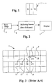
- a second illustrative example is that of a black and white raster display device wherein each pixel can display one of two colours, with black or white.
- each pixel of the display device 3 can only display a restricted number of colours.
- the halftoning process 4 that is actually performed can include dithering or error diffusion.
- each pixel of an array 7 of pixels can display either black (off) or white (on). Assuming that the input image has 256 possible levels of display, a decision must be taken whether to display an on or an off value.
- an output (halftone) value of 0 (or off) is displayed when a derived input value, being the sum of the input value and portions of error values of previously processed pixels, is less than or equal to 127, and and an output value of 1 (or on) is displayed when the derived input value is greater than or equal to 128.
- An error output value e ij for a current pixel 6 being displayed is derived, the error value being the difference between the derived input value and the chosen halftone value. As illustrated in Fig. 3, portions of the error value e ij are then distributed amongst the- surrounding pixels which have not, as yet, been processed.
- Fig. 3 shows one scheme for distributing the error whereby two eighths of the error is added to the value of pixel 8, one eighth is added to the pixel 9, one eighth is added to the pixel 10, two eights is added to the pixel 11, one eighth is added to the pixel 12, and one eighth is added to the pixel 13. This has the effect of spreading, or diffusing, the error over several pixels in the output image.
- error diffusion of a full colour image can be performed by error diffusing each output colour independently.
- a method of error diffusing an image comprising, for each of the pixels, the steps of:
- a method of halftoning an image comprising a plurality of pixels arranged in scan lines, the method comprising the step of error diffusing each pixel of the image characterised in that a halftoned output value of the pixel is determined from error values obtained from substantially all previously halftoned pixels of the image.
- the method comprises, for a current pixel of the image, the specific steps of:
- step (c) comprises selecting a closest one of a plurality of output values to the derived input value and outputting for display the selected value as the halftoned output value.
- the input error value is determined by applying an error diffusion mask to output error values of substantially all of the preceding pixels, the mask having error diffusion coefficients corresponding to each of the substantially all preceding pixels.
- the error diffusion mask comprises at least one two-dimensional array of error diffusion coefficients geometrically decreasing by a first predetermined ratio for each element of the array away from a first predetermined error diffusion coefficient in one dimension of the array and geometrically decreasing by a second predetermined ratio for each element of the array away from the lead position in the other dimension of the array.
- the substantially all preceding pixels are divided into a plurality of groups of pixels and a corresponding mask is applied to each of the groups to provide a corresponding plurality of group error values, the group error values being summed to provide the input error value.
- one or more of the groups comprise wedges of pixels that extend substantially radially from the current pixel.
- apparatus for halftoning an image comprising:
- a computer software system for executing instructions on a general purpose computer, wherein the instructions comprise a plurality of process modules for halftoning an image, the image comprising a plurality of pixels arranged in a plurality of scan lines.
- the modules comprising:
- an error diffusion process (to be hereinafter described) is applied to pixels on a pixel-by-pixel and line-by-line basis, consecutively in a forward direction from a top left-most pixel to a bottom right-most pixel of an image (ie. a raster scan manner).
- the error diffusion process hereinafter described is not limited to such an application.
- the error diffusion process can be applied in a reverse direction from the bottom right-most pixel sequentially, from pixel-to-pixel, to the top left-most pixel of an image.
- the error diffusion process can be applied in the forward direction for every alternate line and in the reverse direction for each line intermediate to every alternate line of the image.
- each pixel 1 of a display device is able to display red, green and blue colour values (RGB), with each colour taking on either a totally "on” or a totally “off” state, to produce in combination a pixel 1 able to display eight (8) possible colours.
- RGB red, green and blue colour values
- the error diffusion process of the various embodiments will be described with reference the monochrome case with white being a totally "on” state and black being a totally "off” state.
- Such an error diffusion process applies equally and independently to each of the three colours (RGB) to produce on the display eight (8) colour combination and a multiplicity of halftoned levels thereof.
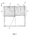
- FIG. 5 there is shown an image 40, where an output pixel value of a current pixel (P i,j ) 41 is to be determined.
- the upper left quadrant 43 comprises all pixels whose output value are known and are in an upper left region of the image 40 relative to the current pixel 41 (ie. pixel locations 1 ⁇ x ⁇ i-1, 1 ⁇ y ⁇ j).
- the term "quadrant" is used herein with some license to indicate an arbitrary area of previously halftoned pixels. Further, each of the quadrants 43 and 44 collectively identify all previously halftoned pixels 42 of the image 40.
- each of the halftoned pixels 42 has associated therewith an output pixel value and an output error value
- an output error value is taken to be a difference between an derived input value of the current pixel 41, and a closest of possible output values of the current pixel 41, wherein the derived input value is a sum of an input value of the current pixel 41 and an input error value calculated as hereinafter described.
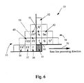
- FIG. 6 there is illustrated an error diffusion mask 50 according to one embodiment.
- a lead position 51 of the error diffusion mask 50 corresponds to an input error of the current pixel 41 being determined by the error diffusion process.
- the error diffusion mask 50 utilises output error values of substantially all halftoned pixels 42 processed prior to the current pixel 41 to determine an input error value for the current pixel 41.
- Each entry position 52 of the error diffusion mask 50 corresponds to a pixel position of the halftoned pixels 42 of the image 40.
- entries in the upper left quadrant 53 of the error diffusion mask 50 correspond to the upper left quadrant 43 of halftoned pixels 42.
- the upper right quadrant 54 entry positions of the error diffusion mask 50 correspond to each halftoned pixel 42 of the upper right quadrant 44 pixels.
- a coefficient 55 represents that fraction of the output error associated with a halftoned pixel which is to be distributed as an input error to the current pixel 41.
- the upper left quadrant 53 entries and the upper right quadrant 54 entries have predetermined initial coefficients 56 and 61 at a first entry position of each quadrant 53 and 54, respectively, adjacent to the lead position 51.
- the error diffusion coefficients 55 reduce in value, preferably, as a geometric sequence for each position entry away from the first entry position of each quadrant 53 and 54. This is illustrated in Fig. 6 and shall further explained as follows with reference to the upper left quadrant 53 of the error diffusion mask 50.
- the upper left quadrant 53 of the error diffusion mask 50 forms an array of coefficients with a first coefficient being the initial coefficient 56 located in the first column, first row of the array and takes on a predetermined value " F ".
- a second coefficient 57 of the upper left quadrant 53 located in the second column and first row of the array takes on a value equal to the first coefficient multiplied by a first predetermined ratio " X " (ie. FX ).
- a third coefficient 58 located in the third column, first row of the array takes on the value of the second coefficient multiplied by the first predetermined ratio (ie. FX 2 ).
- Coefficients on the second row of the upper left quadrant 53 take on the values equal to the coefficients in the first row multiplied by a second predetermined ratio " Y ".
- Coefficients on the third row take on values equal to the coefficients in the second row multiplied by the second predetermined ratio.
- a coefficient of the upper left quadrant 53 of the error diffusion mask 50 located "m" columns and "n" rows away from the first coefficient of the upper left quadrant 53 take on a value equal to the first coefficient multiplied by the first predetermined ratio raised to the power of "m” and further multiplied by the second predetermined ratio raised to the power of "n"(ie. FX m Y n ).
- a coefficient 60 located one column, one row away from the first column, first row take a value equal to FXY .
- all error diffusion coefficients of the upper right quadrant 54 of the error diffusion mask 50 can be determined. wherein a first right coefficient 61 being the entry of the mask 50 above the lead position 51 takes on a corresponding predetermined factor " f ".
- Other coefficients of the upper right quadrant 54 are determined utilizing a third predetermined ratio " p " for each coefficient to the right of the lead position 51 and utilizing a fourth predetermined ratio " q " for each coefficient above the first right coefficient to form, for example, a coefficient value 62 of " fpq " for the position entry of the mask 50 two places above and one place to the right of the lead position 51.
- Fig. 7 relates to a first method of determining the input error contribution and shows the coefficients 55 of upper left quadrant 53 of the error diffusion mask 50 of Fig. 6, and output error values 80 "e x,y " associated with the upper left quadrant 43 of the halftoned pixels 42 of Fig. 5.
- Each error diffusion coefficient 55 is multiplied (indicated by operator 82) by each corresponding entry of the output error values 80, and summed over all output error values 80 to determine an input error contribution 83 to the current pixel value 41 by the upper left quadrant 43 of halftoned pixels 42.
- G xy Fe x,y + FXe x-1,y + FX 2 e x-2,y + ... + FYe x,y-1 + FXYe x-1,y-1 + ... + FY 2 e x,y-2 +...
- the sum of all error diffusion coefficients form a geometrically decreasing series convergent to a single value and the values of the first predetermined ratio " X ", the second predetermined ratio " Y “ and the third and fourth predetermined ratios " p “ and “ q “ respectively take on values between negative one (-1) and one (1).
- an input error contribution to the current pixel 41 by output error values associated with the upper right quadrant 44 of halftoned pixel 42 of Fig. 5, is determined substantially as described above with reference to Fig. 7, utilizing the coefficients of the upper right quadrant 54 of the error diffusion mask 50 shown in Fig. 6.
- Fig. 8 relates to a second method where there is illustrated an iterative process for determining the input error value of the current pixel 41 from a knowledge of the input error values of only a few neighbouring halftoned pixels 42.
- this iterative process only the contribution from the output error values of upper left quadrant 43 of halftoned. pixels 42, and the corresponding upper left quadrant 53 of error diffusion coefficients, is illustrated in Fig. 8. That is, only the input error contribution 83 by the upper left quadrant 43 of halftoned pixels 42 is shown in Fig. 8. From that, the input error contribution to the current pixel 41 by the upper right quadrant 44 of halftoned pixels 42 can be obtained in a substantially similar manner.
- the input error contribution 83 of the current pixel 41 is determined from an input error contribution 84 from an upper left quadrant for a halftoned pixel immediately above the current pixel 41, an input error contribution 85 from an upper left quadrant for a halftoned pixel to the immediate left of the current pixel 41, the output error value of the halftoned pixel to the immediate left of the current pixel 41, and an input error contribution 89 from an upper left quadrant for a halftoned pixel one position up and one position to the left of the current pixel 41.
- the input error contribution 83 to the current pixel 41 by the upper left quadrant 43 can be evaluated from the input error contributions of halftoned pixels 42 adjacent to the current pixel 41.
- F is the predetermined factor, " X “ the first predetermined ratio and " Y “ the second predetermined ratio as hereinbefore described.
- the output error value " e x,y” is the output error value of the " x,y " pixel coordinate position again measured from the top left corner of the image 40.
- Equation 2 A substantially similar equation to that of Equation 2 is utilized in determining the input error contribution of the current pixel 41 from the halftoned pixels 42 belonging to the upper right quadrant 44.
- the input error contribution from the upper left quadrant 43 and the upper right quadrant 44 of the current pixel 41 are preferably summed to form a total input error value for the current pixel 41.
- An output value for the current pixel 41 is then determined from an input value of the current pixel 41 and the total input error value. For example, a sum value being the addition of the input value and the total error value is compared with a predetermined threshold value. If the sum value exceeds the predetermined threshold value, the current pixel 41 is placed in the totally "on” state (ie. the output value is assigned the value of the colour white). If the sum value does not exceed the predetermined threshold value, the current pixel 41 is placed in the totally "off” state (ie. the output value is assigned the value of the colour black).
- an output error value for the current pixel 41 is determined as being the difference of the sum value and the output value for the current pixel 41.
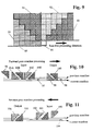
- FIG. 9 A further embodiment is described with reference to Fig. 9 where the previous two quadrants 43 and 44 of Fig. 5, are divided into four wedges 90, 91, 92, and 93 used for the error diffusing of a current pixel 94 and include all previously processed pixels above the broken line 89.
- the present embodiment of error diffusion using wedge values processes an image on a scanline-by-scanline basis, from the top of the image to the bottom.
- the processing for each scanline typically consists of a forward pass followed by a reverse pass of the same scanline illustrated in Figs. 10 and 11.
- processing can also consist of a single pass per scanline.
- the input data consists of:
- the input data consists of:
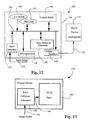
- FIG. 12 shows a computer system 130 including a computer 134 having an output connected to an FLCD device 132.
- the computer 134 includes a system bus 136 to which a controlling microprocessor 138 is connected.
- the computer 134 incorporates a non-volatile random access memory (RAM) in the form of a hard disk 142 and also volatile RAM 144 which is typically formed by semiconductor components.
- RAM non-volatile random access memory
- a read only memory (ROM) device, such as a compact disc device (CD-ROM) 140 also connects to the bus to provide a source of information and controlling programs.
- Coupled to the bus 136 is an input interface 146 via which an input image 150 can be provided to the computer 134.
- either one of the CD-ROM 140 or hard disk 142 can incorporate a computer program configured to perform error diffusion in accordance an embodiment of the present invention.
- the computer program is generally loaded from either one of the CD-ROM 140 or the hard disk 142 into the RAM 144 to enable running of the program.
- An image to be halftoned by error diffusion can be supplied via the input image line 150 or from either one of the CD-ROM 140 or the hard disk 142.
- the microprocessor 138 can, via the program, perform error diffusion of the image.
- the error diffused image can be stored in a frame memory, comprising for example part of the volatile RAM 144 and, once the entire image has been halftoned, the entire image can be transferred to the output interface 148 for display on the FLCD 132.
- the microprocessor 138 can perform the halftoning and via the output interface directly output halftoned pixel values to the FLCD 132 whilst using the RAM 144 as intermediate storage for the various error values and the like used in calculations described above.
- FIG. 12 An alternative arrangement is also seen in Fig. 12 where an optional error diffusion processor 160 connects to the bus 136 and which, under control of the microprocessor 138, is configured to perform specific error diffusion calculations and operations in hardware thus releasing the microprocessor 138 from complicated calculations and thus permitting it to perform other management operations necessary for the control of the system 130.
- an optional error diffusion processor 160 connects to the bus 136 and which, under control of the microprocessor 138, is configured to perform specific error diffusion calculations and operations in hardware thus releasing the microprocessor 138 from complicated calculations and thus permitting it to perform other management operations necessary for the control of the system 130.
- Arrangements such as those shown in Fig. 12 can be useful in computing and other applications where the image update time is not crucial to system performance.
- a software implementation of the present invention may not be sufficiently fast so as to achieve real-time image display (eg. 25 frames per second in the PAIL colour system).
- real-time image display e. 25 frames per second in the PAIL colour system.
- Fig. 13 shows a display device 170 including an FLCD display panel 190 supplied with halftoned pixel data from an error diffusion processor 180.
- the processor 180 is input with (substantially continuous tone) pixel data 182 derived from a suitable source of such data including a video device, such as a television receiver, or a general purpose computer, for example.
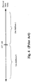
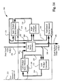
- Fig. 14 illustrates an exemplary embodiment of an error diffusion processor 200, the general configuration of which can be applied to a number of the embodiments described above.
- a stream of pixel input values 202 are supplied to a pixel result calculator 204.
- the calculator 204 provides a pixel halftone output value 206, representing a display output of the processor 200.
- the calculator 204 also outputs pixel error values via a line 208 to a pixel result serial memory 210 and also to a left wedges calculator 212.
- the left wedges calculator 212 determines left wedge error values which are output 224 to a left wedges serial memory 226.
- the memory 226 includes a return line 228 to the left wedges calculator 212, and an output line 230 to the pixel result calculator 204.
- the pixel result serial memory 210 includes an output 213 that supplies an input to a right wedges calculator 214.
- the right wedges calculator 214 determines right wedge error values which are output 216 to a right wedges serial memory 218.
- the serial memory 218 includes two outputs, a first output 222 which supplies a further input of the right wedges calculator 219, and a second output 220 which supplies both a further input of the right wedges serial memory 218 and also a further input of the pixel result calculator 204.
- Each of the memories 210, 226 and 218 incorporate a "direction" input which is supplied with a signal 232 representing the calculation direction being performed on the particular forward or reverse pass as noted above.
- the signal 232 is a logical 1 (forward pass)
- the left wedges serial memory 226 shifts from left to right
- both the right wedges serial memory 218 and the pixel result serial memory 210 shift from left to right.
- the signal 232 is a logical 0 (reverse pass)
- the left wedges serial memory 226 does not shift and both the right wedges serial memory 218 and the pixel result serial memory 210 shift from right to left.
- the processor 200 is advantageous in that its structure permits receipt of a serial pixel stream as input and provides a corresponding pixel output stream in a form ready for display and in reliance only upon a controlling forward/reverse pass signal 232. Further, each of the calculators 204, 212 and 218 can be configured in silicon at gate level thereby permitting real-time operation and hence the display of image sequences without any noticeable delay due to the halftoning process.
Landscapes
- Engineering & Computer Science (AREA)
- Multimedia (AREA)
- Signal Processing (AREA)
- Image Processing (AREA)
- Facsimile Image Signal Circuits (AREA)
Applications Claiming Priority (2)
| Application Number | Priority Date | Filing Date | Title |
|---|---|---|---|
| AUPN7413A AUPN741396A0 (en) | 1996-01-05 | 1996-01-05 | Geometrically reducing mask error diffusion |
| AUPN7413/96 | 1996-01-05 |
Publications (2)
| Publication Number | Publication Date |
|---|---|
| EP0783224A2 true EP0783224A2 (de) | 1997-07-09 |
| EP0783224A3 EP0783224A3 (de) | 1998-06-03 |
Family
ID=3791732
Family Applications (1)
| Application Number | Title | Priority Date | Filing Date |
|---|---|---|---|
| EP97300037A Withdrawn EP0783224A3 (de) | 1996-01-05 | 1997-01-06 | Fehlerdiffusion mit einer geometrisch reduzierenden Maske |
Country Status (4)
| Country | Link |
|---|---|
| US (1) | US6108452A (de) |
| EP (1) | EP0783224A3 (de) |
| JP (1) | JPH09305756A (de) |
| AU (2) | AUPN741396A0 (de) |
Families Citing this family (7)
| Publication number | Priority date | Publication date | Assignee | Title |
|---|---|---|---|---|
| US6476934B1 (en) * | 1997-01-02 | 2002-11-05 | Canon Kabushiki Kaisha | Geometrically reducing influence halftoning |
| US7355747B2 (en) * | 2002-01-18 | 2008-04-08 | Hewlett-Packard Development Company, L.P. | System for improving the speed of data processing |
| US20050219623A1 (en) * | 2003-07-23 | 2005-10-06 | Konica Minolta Holdings, Inc. | Image processing apparatus and image processing method |
| US7450270B2 (en) * | 2004-01-16 | 2008-11-11 | Hewlett-Packard Development Company, L.P. | Image data processing methods, hard imaging devices, and articles of manufacture |
| JP3995002B2 (ja) * | 2005-01-24 | 2007-10-24 | セイコーエプソン株式会社 | 画像処理装置、画像処理方法、およびプログラム |
| JP5600517B2 (ja) | 2010-08-18 | 2014-10-01 | キヤノン株式会社 | 情報処理装置、情報処理方法、およびプログラム |
| JP6119322B2 (ja) * | 2013-03-13 | 2017-04-26 | セイコーエプソン株式会社 | 画像データ処理装置、印刷装置および印刷システム |
Family Cites Families (5)
| Publication number | Priority date | Publication date | Assignee | Title |
|---|---|---|---|---|
| DE3067060D1 (en) * | 1979-12-20 | 1984-04-19 | Cambridge Consultants | Apparatus and method for generating a dispersed dot half tone picture from a continuous tone picture |
| JP2645379B2 (ja) * | 1987-03-17 | 1997-08-25 | ディジタル イクイプメント コーポレーション | 連続トーン・イメージ・データからディザード・イメージを作成するシステム |
| WO1989006080A1 (en) * | 1987-12-17 | 1989-06-29 | Eastman Kodak Company | Image processor with error diffusion modulated threshold matrix |
| US5353127A (en) * | 1993-12-15 | 1994-10-04 | Xerox Corporation | Method for quantization gray level pixel data with extended distribution set |
| US5692109A (en) * | 1994-07-01 | 1997-11-25 | Seiko Epson Corporation | Method and apparatus for minimizing artifacts in images produced by error diffusion halftoning |
-
1996
- 1996-01-05 AU AUPN7413A patent/AUPN741396A0/en not_active Abandoned
-
1997
- 1997-01-06 JP JP9000397A patent/JPH09305756A/ja not_active Withdrawn
- 1997-01-06 US US08/779,357 patent/US6108452A/en not_active Expired - Fee Related
- 1997-01-06 AU AU10040/97A patent/AU712262B2/en not_active Ceased
- 1997-01-06 EP EP97300037A patent/EP0783224A3/de not_active Withdrawn
Non-Patent Citations (1)
| Title |
|---|
| None |
Also Published As
| Publication number | Publication date |
|---|---|
| JPH09305756A (ja) | 1997-11-28 |
| AUPN741396A0 (en) | 1996-01-25 |
| US6108452A (en) | 2000-08-22 |
| EP0783224A3 (de) | 1998-06-03 |
| AU712262B2 (en) | 1999-11-04 |
| AU1004097A (en) | 1997-07-10 |
Similar Documents
| Publication | Publication Date | Title |
|---|---|---|
| US5553165A (en) | Parallel error diffusion method and apparatus | |
| EP0606987B1 (de) | Paralleles Fehlerdiffusionsverfahren und -gerät | |
| US6476934B1 (en) | Geometrically reducing influence halftoning | |
| EP0606992A2 (de) | Halbtonzitteroptimierungstechniken | |
| KR960019054A (ko) | 디스플레이의 구동방법 및 장치 | |
| EP1515278B1 (de) | Videokompression unter Verwendung von Dithering | |
| US6124844A (en) | Force field halftoning | |
| EP0725533A2 (de) | Verarbeitung von halbtongerasterten Farbbildern | |
| JPH0865509A (ja) | 誤差拡散方法及び誤差拡散システム | |
| US6108452A (en) | Geometrically reducing mask error diffusion | |
| EP0824822B1 (de) | System und verfahren zur stochastischen rasterung mit mehreren dichtepegeln | |
| KR100354742B1 (ko) | 화상 데이터 처리장치 | |
| US7565027B2 (en) | Countdown stamp error diffusion | |
| JPH0738767A (ja) | 画像2値化処理装置 | |
| US5444461A (en) | Bi-dimensional visual model | |
| US20050129309A1 (en) | Error diffusion method and apparatus using area ratio in CMYKRGBW cube | |
| AU723183B2 (en) | Force field halftoning | |
| JP3287717B2 (ja) | 画像処理装置 | |
| JPS6223353B2 (de) | ||
| JP2003198843A (ja) | 削減されたバッファでのエラー拡散 | |
| AU729264B2 (en) | Geometrically reducing influence halftoning | |
| JPH0668250A (ja) | 画像処理装置 | |
| US20050275899A1 (en) | Dithering method and related apparatus using aperiodic tiling rule | |
| JPH01212073A (ja) | 画像データ縮小処理装置 | |
| JP2867487B2 (ja) | 画像処理方法 |
Legal Events
| Date | Code | Title | Description |
|---|---|---|---|
| PUAI | Public reference made under article 153(3) epc to a published international application that has entered the european phase |
Free format text: ORIGINAL CODE: 0009012 |
|
| AK | Designated contracting states |
Kind code of ref document: A2 Designated state(s): DE FR GB IT |
|
| PUAL | Search report despatched |
Free format text: ORIGINAL CODE: 0009013 |
|
| AK | Designated contracting states |
Kind code of ref document: A3 Designated state(s): DE FR GB IT |
|
| 17P | Request for examination filed |
Effective date: 19980813 |
|
| 17Q | First examination report despatched |
Effective date: 20001108 |
|
| STAA | Information on the status of an ep patent application or granted ep patent |
Free format text: STATUS: THE APPLICATION IS DEEMED TO BE WITHDRAWN |
|
| 18D | Application deemed to be withdrawn |
Effective date: 20010320 |