EP0783453B1 - Sicherheitsauslösevorrichtung bei einem geradlinigen riementrieb für automatisch öffnende türen von aufzügen und senkrechtförderern - Google Patents
Sicherheitsauslösevorrichtung bei einem geradlinigen riementrieb für automatisch öffnende türen von aufzügen und senkrechtförderern Download PDFInfo
- Publication number
- EP0783453B1 EP0783453B1 EP95916838A EP95916838A EP0783453B1 EP 0783453 B1 EP0783453 B1 EP 0783453B1 EP 95916838 A EP95916838 A EP 95916838A EP 95916838 A EP95916838 A EP 95916838A EP 0783453 B1 EP0783453 B1 EP 0783453B1
- Authority
- EP
- European Patent Office
- Prior art keywords
- belt
- coaster
- door
- release device
- internal element
- Prior art date
- Legal status (The legal status is an assumption and is not a legal conclusion. Google has not performed a legal analysis and makes no representation as to the accuracy of the status listed.)
- Expired - Lifetime
Links
- 230000005540 biological transmission Effects 0.000 title claims description 6
- 230000033001 locomotion Effects 0.000 claims abstract description 8
- 230000008878 coupling Effects 0.000 claims description 7
- 238000010168 coupling process Methods 0.000 claims description 7
- 238000005859 coupling reaction Methods 0.000 claims description 7
- 230000006835 compression Effects 0.000 claims description 2
- 238000007906 compression Methods 0.000 claims description 2
- 230000015556 catabolic process Effects 0.000 description 3
- 230000002159 abnormal effect Effects 0.000 description 1
- 230000006378 damage Effects 0.000 description 1
- 230000000694 effects Effects 0.000 description 1
- 230000002452 interceptive effect Effects 0.000 description 1
- 230000007246 mechanism Effects 0.000 description 1
- 238000013021 overheating Methods 0.000 description 1
- 230000002441 reversible effect Effects 0.000 description 1
Images

Classifications
-
- B—PERFORMING OPERATIONS; TRANSPORTING
- B66—HOISTING; LIFTING; HAULING
- B66B—ELEVATORS; ESCALATORS OR MOVING WALKWAYS
- B66B13/00—Doors, gates, or other apparatus controlling access to, or exit from, cages or lift well landings
- B66B13/24—Safety devices in passenger lifts, not otherwise provided for, for preventing trapping of passengers
- B66B13/26—Safety devices in passenger lifts, not otherwise provided for, for preventing trapping of passengers between closing doors
-
- E—FIXED CONSTRUCTIONS
- E05—LOCKS; KEYS; WINDOW OR DOOR FITTINGS; SAFES
- E05F—DEVICES FOR MOVING WINGS INTO OPEN OR CLOSED POSITION; CHECKS FOR WINGS; WING FITTINGS NOT OTHERWISE PROVIDED FOR, CONCERNED WITH THE FUNCTIONING OF THE WING
- E05F15/00—Power-operated mechanisms for wings
- E05F15/40—Safety devices, e.g. detection of obstructions or end positions
- E05F15/41—Detection by monitoring transmitted force or torque; Safety couplings with activation dependent upon torque or force, e.g. slip couplings
-
- E—FIXED CONSTRUCTIONS
- E05—LOCKS; KEYS; WINDOW OR DOOR FITTINGS; SAFES
- E05Y—INDEXING SCHEME ASSOCIATED WITH SUBCLASSES E05D AND E05F, RELATING TO CONSTRUCTION ELEMENTS, ELECTRIC CONTROL, POWER SUPPLY, POWER SIGNAL OR TRANSMISSION, USER INTERFACES, MOUNTING OR COUPLING, DETAILS, ACCESSORIES, AUXILIARY OPERATIONS NOT OTHERWISE PROVIDED FOR, APPLICATION THEREOF
- E05Y2900/00—Application of doors, windows, wings or fittings thereof
- E05Y2900/10—Application of doors, windows, wings or fittings thereof for buildings or parts thereof
- E05Y2900/104—Application of doors, windows, wings or fittings thereof for buildings or parts thereof for elevators
Definitions
- the invention relates to a safety release device operating in a linear belt or cable transmission for lift gates and for automatically opening lifts and elevators.
- the opening operation is generally driven by a motor which sets a pulley in rotation.
- a belt or closed cable is wound about the pulley to create the movement which sets the coasters bearing the doors in motion.
- Said coasters are anchored to the belt or cable, either directly or by means of intermediate elements, such that each rotation direction of the belt or cable corresponds to a reciprocal nearing or distancing of the coasters and thus an opening or closing of the doors.
- a safety release device which stops the motor and is also able to reactivate the doors in the opposite direction.
- the main aim of the present invention is to eliminate the above-mentioned drawbacks and provide a safety device of an exclusively mechanical type, and which is therefore not subject to breakdowns due to electrical or electronic faults, and which can be applied in automatically-opening doors of the belt, chain or cable linear transmission type.
- the safety release device object of the present invention which is characterized as in the following claims, and in particular in that said release device is shaped such that, during the door-closing phase, when a predetermined resistence threshold encountered by the doors is exceeded, the door-bearing coasters are freed from their belt or cable and thus stop, while the belt or cable continues to function.
- the safety device one for each gate, is stably anchored to the coaster and therefore to the chain or cable by means for maintaining a pressure which enable the coaster to be released from the cable or belt once a contrast force exerted by the means for maintaining a pressure has been overcome.
- the device of the invention comprises a first, a second and a third elements.
- the release device 4 further comprises a second, external element 2 and a third element, in this embodiment a platelet 3, both of which cooperate with the internal element 1.
- 5 denotes a transmission belt ring-wound about a pulley pair (not illustrated), of which pulleys one is motorised while the other is idle.
- the internal element 1, illustrated in greater detail in figures 2, 3 and 4, is solidly constrained to the belt 5, and comprises an internal part, constituted by two shells 1a and 1b which embrace the belt 5 and insert in an external part 1c which envelopes the two shells 1a and 1b.
- the internal element 1 is fixed to the belt 5 by means of two screws (not illustrated) which insert in through holes 8 afforded by the two shells 1a and 1b and the external part 1c.
- said internal element 1 also constitutes a sort of fastener for the belt, the free ends thereof being trapped internally thereof.
- the internal element 1 is externally cylindrical with a conical end, and is specially shaped to provide a seat 9 in its lateral external surface.
- the external element 2 of the release device 4, illustrated in greater detail in figures 5, 6 and 7, is a hollow element, fixed by means of screws 7 to a door-bearing coaster 6, partially illustrated in figure 1 and of known type.
- Each gate comprises a variable number of coasters 6, each of which inferiorly supports a door of a lift or elevator.
- the release device 4, one for each gate, is applied on the belt 5, which might also be a cable and which constitutes means for moving the coasters 6.
- the external element 2 is conformed such as to house the internal element 1, as illustrated in figure 1, in one sense only; it also constitutes an endrun stop for said internal element.
- the external 2 and internal 1 elements thus achieve a reversible male-female coupling.
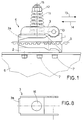
- a third element making up the release device 4 is illustrated in figures 1 and 8 and is constituted by a platelet 3 provided with a rounded end 3a for attachment of the external element 2 and an idle roller 10 destined to interact with the internal element 1 and insert thereon at the specially shaped seat 9, as can be seen in figure 1.
- the curved end 3a inserts in a corresponding channel 18 exhibited by the external element 2.
- a compression spring 11 acts on the platelet 3 and keeps it pressed against the internal element 1 and the external element 2 such that the idle roller 10 remains in the shaped seat 9 and constrains the coaster 6 to the belt 5, thus permitting transport of the coaster 6 and the door when the belt 5 is moved by the motor.
- All the coasters 6 are operatively connected to the belt 5 such that when the belt 5 rotates about the pulleys, corresponding pairs of doors either reciprocally distance or near (in doors opening centrally) or all segments in a single door move (in laterally-opening telescopic doors).
- the platelet 3 lifts slightly at the rounded end 10 and allows the internal element 1 to exit from its housing in the external element 2.
- the adjustment nut 12 denotes an adjustment nut which is screwable on a central axis 15 of the spring, which axis 15 passes through a hole 16 in the platelet 3 and screws into a blindhole 17 in the external element 2.
- the adjustment nut 12 serves to adjustt the pressure force exerted by the spring 11 on the platelet 3 and thus to determine the intervention threshold of the release device 4.
- the release device 4 of the present invention enables door movement to be stopped during the closing phase thereof by means only of mechanical components. No electrical or electronic components are needed, and a resultingly greater level of safety is guaranteed.
- a further advantage of the present device is that the shells 1a and 1b of the internal element 1 also lock the free ends of the belt 5, creating in effect a closed belt which achieves the double aim of constituting part of the release device as well as a sort of fastener for the belt 5 itself.
Landscapes
- Power-Operated Mechanisms For Wings (AREA)
- Elevator Door Apparatuses (AREA)
- Maintenance And Inspection Apparatuses For Elevators (AREA)
- Devices For Conveying Motion By Means Of Endless Flexible Members (AREA)
- Automotive Seat Belt Assembly (AREA)
Claims (7)
- Sicherheitsausklinkvorrichtung mit linearem Riemen- oder Seilantrieb für ein- oder zweiflügelige Türen von Aufzügen mit und ohne automatischer Öffnung, der Art, die einen oder mehrere Flügeltragwägen (6) umfasst, die linear in gegenläufiger Öffnungs- und Schliessrichtung der Tür gleiten, wobei mit diesen Wägen Fördermittel kinematisch verbunden sind, die einen Riemen oder ein Seil (5) umfassen,
dadurch gekennzeichnet, dass die Vorrichtung eine an dem Riemen oder Seil (5) angebrachte Ausklinkvorrichtung (4) umfasst, die während des Schliessvorgangs der Türflügel die Flügeltragwägen (6) von dem Riemen oder Seil (5) löst, wenn die Türflügel beim Schliessen einen vorbestimmten Widerstand überschreiten, so dass die Wägen (6) und Flügel zum Stillstand gebracht werden, während hingegen die Funktion des Riemens oder Seiles (5) aufrecht erhalten wird; dabei ist die Ausklinkvorrichtung (4) so ausgebildet, dass sie zumindest ein fest mit einem Wagen (6) verankertes Element und ein fest mit dem Riemen (5) verankertes Element umfasst; wobei Druckmittel zur Aufrechterhaltung der Verbindung der Elemente untereinander und zur Lösung dieser Verbindung und der Lösung des Wagens (6) von dem Riemen (5) bei Überschreiten der von den Druckmitteln ausgeübten Gegenkraft vorgesehen sind. - Vorrichtung nach Anspruch 1, dadurch gekennzeichnet, dass die Ausklinkvorrichtung folgendes umfasst:ein inneres Element (1), das fest mit dem Riemen (5) verbunden ist;ein äusseres Element (2), das fest mit dem Wagen (6) verbunden und so ausgebildet ist, dass eine Art Aufnahme für das innere Element (1) gebildet wird;ein Plättchen (3), das mit dem inneren (1) und äusseren (2) Element zusammenwirkt und deren Verbindung aufrechterhält bzw. löst, wobei dieses Plättchen durch die Druckmittel (11) gegen die Elemente gedrückt wird.
- Vorrichtung nach Anspruch 2, bei der die Druckmittel aus einer Druckfeder (11) bestehen.
- Vorrichtung nach Anspruch 3, dadurch gekennzeichnet, dass sie zur Einstellung der von der Feder (11) auf das Plättchen (3) ausgeübten Kraft eine auf eine Mittelachse (15) der Feder aufgeschraubte Einstellmutter (12) umfasst.
- Vorrichtung nach Anspruch 2, bei der das äussere Element (2) so ausgebildet ist, dass es das innere Element (1) nur in einer Eintrittsrichtung aufnimmt und ferner einen Endschalter für das innere Element (1) bildet.
- Vorrichtung nach Anspruch 1, bei der das innere Element (1) aus einem Paar gleicher Teile (1a,1b) besteht, das den Riemen (5) umgreift und sich in ein die beiden gleichen Teile umfassendes Aussenteil (1c) einfügt, wobei die gleichen Teile (1a,1b) den Riemen (5) bei der Verbindung des Riemens umgreifen, so dass ein Verschlussglied für den Riemen gebildet wird.
- Vorrichtung nach Anspruch 1, bei der die Ausklinkvorrichtung (4) so ausgebildet ist, dass sie gleichzeitig auch eine Verschlusseinrichtung oder ein Versclussglied für den Riemen (5) bildet.
Applications Claiming Priority (3)
| Application Number | Priority Date | Filing Date | Title |
|---|---|---|---|
| ITPR940037 | 1994-09-30 | ||
| ITPR940037A IT1274194B (it) | 1994-09-30 | 1994-09-30 | Dispositivo di sgancio di sicurezza in trasmissione lineare a cinghia o a fune per porte di ascensori ed elevatori ad apertura automatica |
| PCT/IT1995/000058 WO1996010531A1 (en) | 1994-09-30 | 1995-04-21 | A safety release device operating in a linear belt transmission for automatically-opening lift and elevator gates |
Publications (2)
| Publication Number | Publication Date |
|---|---|
| EP0783453A1 EP0783453A1 (de) | 1997-07-16 |
| EP0783453B1 true EP0783453B1 (de) | 1998-03-11 |
Family
ID=11395905
Family Applications (1)
| Application Number | Title | Priority Date | Filing Date |
|---|---|---|---|
| EP95916838A Expired - Lifetime EP0783453B1 (de) | 1994-09-30 | 1995-04-21 | Sicherheitsauslösevorrichtung bei einem geradlinigen riementrieb für automatisch öffnende türen von aufzügen und senkrechtförderern |
Country Status (14)
| Country | Link |
|---|---|
| US (1) | US5732797A (de) |
| EP (1) | EP0783453B1 (de) |
| JP (1) | JPH10506359A (de) |
| KR (1) | KR100254137B1 (de) |
| CN (1) | CN1054352C (de) |
| AT (1) | ATE163900T1 (de) |
| AU (1) | AU2318895A (de) |
| DE (1) | DE69501788T2 (de) |
| ES (1) | ES2115378T3 (de) |
| FI (1) | FI112643B (de) |
| IL (1) | IL115474A (de) |
| IT (1) | IT1274194B (de) |
| TR (1) | TR199501184A2 (de) |
| WO (1) | WO1996010531A1 (de) |
Families Citing this family (6)
| Publication number | Priority date | Publication date | Assignee | Title |
|---|---|---|---|---|
| IT1285374B1 (it) * | 1996-05-28 | 1998-06-03 | Tesio Srl | Dispositivo di comando per porte di ascensori |
| FR2772066B1 (fr) * | 1997-12-09 | 2000-02-25 | Ruchat Rene | Mecanisme de securite dans un dispositif motorise d'ouverture et de fermeture d'une porte coulissante de vehicule |
| ES2221823T3 (es) * | 2000-06-26 | 2005-01-16 | Multimatic Inc. | Sistema automatico de apertura/cierre de puerta deslizante. |
| ITPR20010005A1 (it) * | 2001-01-24 | 2002-07-25 | Selcom Spa | Apparato di movimentazione delle ante, in ascensore od elevatore con porte ad apertura automatica delle ante. |
| CN107150943B (zh) * | 2017-07-13 | 2019-01-01 | 苏州菱高快速电梯有限公司 | 一种防夹人电梯 |
| CN107140511B (zh) * | 2017-07-13 | 2018-12-28 | 苏州菱高快速电梯有限公司 | 一种安全的曳引电梯 |
Family Cites Families (5)
| Publication number | Priority date | Publication date | Assignee | Title |
|---|---|---|---|---|
| US4057934A (en) * | 1974-04-05 | 1977-11-15 | Hitachi, Ltd. | Protection system for automatically openable and closable door |
| JPS553272B2 (de) * | 1974-04-05 | 1980-01-24 | ||
| CH663608A5 (de) * | 1984-05-28 | 1987-12-31 | Inventio Ag | Tuerantrieb mit einklemmsicherung fuer tueren von aufzugskabinen. |
| US5213182A (en) * | 1991-11-19 | 1993-05-25 | Otis Elevator Company | Elevator door operator cog belt linkage |
| IT1259024B (it) * | 1992-05-21 | 1996-03-11 | Operatore lineare, a frizione,per porte d'ascensori |
-
1994
- 1994-09-30 IT ITPR940037A patent/IT1274194B/it active IP Right Grant
-
1995
- 1995-04-21 EP EP95916838A patent/EP0783453B1/de not_active Expired - Lifetime
- 1995-04-21 AT AT95916838T patent/ATE163900T1/de not_active IP Right Cessation
- 1995-04-21 KR KR1019970701558A patent/KR100254137B1/ko not_active Expired - Fee Related
- 1995-04-21 JP JP8511581A patent/JPH10506359A/ja not_active Ceased
- 1995-04-21 WO PCT/IT1995/000058 patent/WO1996010531A1/en not_active Ceased
- 1995-04-21 DE DE69501788T patent/DE69501788T2/de not_active Expired - Lifetime
- 1995-04-21 ES ES95916838T patent/ES2115378T3/es not_active Expired - Lifetime
- 1995-04-21 AU AU23188/95A patent/AU2318895A/en not_active Abandoned
- 1995-04-21 CN CN95195410A patent/CN1054352C/zh not_active Expired - Fee Related
- 1995-09-29 TR TR95/01184A patent/TR199501184A2/xx unknown
- 1995-10-01 IL IL11547495A patent/IL115474A/en not_active IP Right Cessation
-
1997
- 1997-03-04 FI FI970926A patent/FI112643B/fi active
- 1997-03-18 US US08/821,973 patent/US5732797A/en not_active Expired - Fee Related
Also Published As
| Publication number | Publication date |
|---|---|
| US5732797A (en) | 1998-03-31 |
| KR100254137B1 (ko) | 2000-04-15 |
| EP0783453A1 (de) | 1997-07-16 |
| FI112643B (fi) | 2003-12-31 |
| CN1172461A (zh) | 1998-02-04 |
| ATE163900T1 (de) | 1998-03-15 |
| ES2115378T3 (es) | 1998-06-16 |
| DE69501788T2 (de) | 1998-08-06 |
| JPH10506359A (ja) | 1998-06-23 |
| FI970926A0 (fi) | 1997-03-04 |
| DE69501788D1 (de) | 1998-04-16 |
| AU2318895A (en) | 1996-04-26 |
| ITPR940037A0 (it) | 1994-09-30 |
| TR199501184A2 (tr) | 1996-06-21 |
| WO1996010531A1 (en) | 1996-04-11 |
| ITPR940037A1 (it) | 1996-03-30 |
| IT1274194B (it) | 1997-07-15 |
| IL115474A (en) | 1998-09-24 |
| IL115474A0 (en) | 1996-01-19 |
| FI970926L (fi) | 1997-03-13 |
| CN1054352C (zh) | 2000-07-12 |
Similar Documents
| Publication | Publication Date | Title |
|---|---|---|
| US6561255B1 (en) | Overhead door locking operator | |
| US4159598A (en) | Door operator with instant reverse feature | |
| US5323876A (en) | Elevator door mechanism | |
| EP1870552A2 (de) | Vorrichtung zur Schließfolgeregelung für zweiflügelige Drehtüren | |
| US2378262A (en) | Door or like operating device | |
| EP0783453B1 (de) | Sicherheitsauslösevorrichtung bei einem geradlinigen riementrieb für automatisch öffnende türen von aufzügen und senkrechtförderern | |
| US5974737A (en) | Self-opening entry device for a controlled access area | |
| EP0142039B1 (de) | Vorrichtung zum automatischen Öffnen und Schliessen von Schiebetüren | |
| US4900294A (en) | Garage door opener drive mechanism | |
| US3344556A (en) | Door operating device | |
| EP1870551A2 (de) | Vorrichtung zur Schließfolgeregelung für zweiflügelige Drehtüren | |
| DE3202784A1 (de) | Automatische schiebetueranlage | |
| KR100279730B1 (ko) | 안전 도어클로저 | |
| DE9200341U1 (de) | Antrieb für eine Schiebetüranlage mit zwei Schiebeflügeln | |
| EP1870550A2 (de) | Vorrichtung zur Schließfolgeregelung für zweiflügelige Drehtüren | |
| KR200424974Y1 (ko) | 타이밍벨트 이탈방지부재가 구비된 슬라이딩도어 | |
| CN216105490U (zh) | 一种安全型轿箱开门机构 | |
| JPH074162A (ja) | シャッタ、主にローラシャッタのための駆動装置 | |
| KR102740278B1 (ko) | 미닫이문 자동개폐장치 | |
| JP2503741B2 (ja) | エレベ―タ―のドア装置 | |
| GB2396658A (en) | Automated door opener including pivoting lever or track mechanism | |
| CN116516863A (zh) | 一种具有减速缓冲功能的闸机 | |
| JPH0419025Y2 (de) | ||
| RU2114044C1 (ru) | Лифт | |
| KR20010108918A (ko) | 엘리베이터 도어개폐장치의 구조 |
Legal Events
| Date | Code | Title | Description |
|---|---|---|---|
| PUAI | Public reference made under article 153(3) epc to a published international application that has entered the european phase |
Free format text: ORIGINAL CODE: 0009012 |
|
| GRAG | Despatch of communication of intention to grant |
Free format text: ORIGINAL CODE: EPIDOS AGRA |
|
| 17P | Request for examination filed |
Effective date: 19970319 |
|
| AK | Designated contracting states |
Kind code of ref document: A1 Designated state(s): AT BE CH DE DK ES FR GB GR IT LI NL PT SE |
|
| AX | Request for extension of the european patent |
Free format text: SI PAYMENT 970311 |
|
| 17Q | First examination report despatched |
Effective date: 19970717 |
|
| GRAG | Despatch of communication of intention to grant |
Free format text: ORIGINAL CODE: EPIDOS AGRA |
|
| GRAH | Despatch of communication of intention to grant a patent |
Free format text: ORIGINAL CODE: EPIDOS IGRA |
|
| GRAH | Despatch of communication of intention to grant a patent |
Free format text: ORIGINAL CODE: EPIDOS IGRA |
|
| GRAA | (expected) grant |
Free format text: ORIGINAL CODE: 0009210 |
|
| AK | Designated contracting states |
Kind code of ref document: B1 Designated state(s): AT BE CH DE DK ES FR GB GR IT LI NL PT SE |
|
| AX | Request for extension of the european patent |
Free format text: SI PAYMENT 970311 |
|
| PG25 | Lapsed in a contracting state [announced via postgrant information from national office to epo] |
Ref country code: NL Free format text: LAPSE BECAUSE OF FAILURE TO SUBMIT A TRANSLATION OF THE DESCRIPTION OR TO PAY THE FEE WITHIN THE PRESCRIBED TIME-LIMIT Effective date: 19980311 Ref country code: GR Free format text: LAPSE BECAUSE OF FAILURE TO SUBMIT A TRANSLATION OF THE DESCRIPTION OR TO PAY THE FEE WITHIN THE PRESCRIBED TIME-LIMIT Effective date: 19980311 Ref country code: BE Free format text: LAPSE BECAUSE OF FAILURE TO SUBMIT A TRANSLATION OF THE DESCRIPTION OR TO PAY THE FEE WITHIN THE PRESCRIBED TIME-LIMIT Effective date: 19980311 Ref country code: AT Free format text: LAPSE BECAUSE OF FAILURE TO SUBMIT A TRANSLATION OF THE DESCRIPTION OR TO PAY THE FEE WITHIN THE PRESCRIBED TIME-LIMIT Effective date: 19980311 |
|
| REF | Corresponds to: |
Ref document number: 163900 Country of ref document: AT Date of ref document: 19980315 Kind code of ref document: T |
|
| REG | Reference to a national code |
Ref country code: CH Ref legal event code: EP |
|
| ITF | It: translation for a ep patent filed | ||
| REF | Corresponds to: |
Ref document number: 69501788 Country of ref document: DE Date of ref document: 19980416 |
|
| REG | Reference to a national code |
Ref country code: CH Ref legal event code: NV Representative=s name: BUGNION S.A. |
|
| ET | Fr: translation filed | ||
| PG25 | Lapsed in a contracting state [announced via postgrant information from national office to epo] |
Ref country code: SE Free format text: LAPSE BECAUSE OF FAILURE TO SUBMIT A TRANSLATION OF THE DESCRIPTION OR TO PAY THE FEE WITHIN THE PRESCRIBED TIME-LIMIT Effective date: 19980611 Ref country code: DK Free format text: LAPSE BECAUSE OF FAILURE TO SUBMIT A TRANSLATION OF THE DESCRIPTION OR TO PAY THE FEE WITHIN THE PRESCRIBED TIME-LIMIT Effective date: 19980611 |
|
| PG25 | Lapsed in a contracting state [announced via postgrant information from national office to epo] |
Ref country code: PT Free format text: LAPSE BECAUSE OF FAILURE TO SUBMIT A TRANSLATION OF THE DESCRIPTION OR TO PAY THE FEE WITHIN THE PRESCRIBED TIME-LIMIT Effective date: 19980615 |
|
| REG | Reference to a national code |
Ref country code: ES Ref legal event code: FG2A Ref document number: 2115378 Country of ref document: ES Kind code of ref document: T3 |
|
| NLV1 | Nl: lapsed or annulled due to failure to fulfill the requirements of art. 29p and 29m of the patents act | ||
| PLBE | No opposition filed within time limit |
Free format text: ORIGINAL CODE: 0009261 |
|
| STAA | Information on the status of an ep patent application or granted ep patent |
Free format text: STATUS: NO OPPOSITION FILED WITHIN TIME LIMIT |
|
| 26N | No opposition filed | ||
| REG | Reference to a national code |
Ref country code: GB Ref legal event code: IF02 |
|
| PGFP | Annual fee paid to national office [announced via postgrant information from national office to epo] |
Ref country code: GB Payment date: 20080423 Year of fee payment: 14 |
|
| GBPC | Gb: european patent ceased through non-payment of renewal fee |
Effective date: 20090421 |
|
| PG25 | Lapsed in a contracting state [announced via postgrant information from national office to epo] |
Ref country code: GB Free format text: LAPSE BECAUSE OF NON-PAYMENT OF DUE FEES Effective date: 20090421 |
|
| PGFP | Annual fee paid to national office [announced via postgrant information from national office to epo] |
Ref country code: CH Payment date: 20120430 Year of fee payment: 18 |
|
| REG | Reference to a national code |
Ref country code: CH Ref legal event code: PL |
|
| PG25 | Lapsed in a contracting state [announced via postgrant information from national office to epo] |
Ref country code: LI Free format text: LAPSE BECAUSE OF NON-PAYMENT OF DUE FEES Effective date: 20130430 Ref country code: CH Free format text: LAPSE BECAUSE OF NON-PAYMENT OF DUE FEES Effective date: 20130430 |
|
| PGFP | Annual fee paid to national office [announced via postgrant information from national office to epo] |
Ref country code: IT Payment date: 20140423 Year of fee payment: 20 Ref country code: ES Payment date: 20140522 Year of fee payment: 20 Ref country code: FR Payment date: 20140428 Year of fee payment: 20 Ref country code: DE Payment date: 20140627 Year of fee payment: 20 |
|
| REG | Reference to a national code |
Ref country code: DE Ref legal event code: R071 Ref document number: 69501788 Country of ref document: DE |
|
| REG | Reference to a national code |
Ref country code: DE Ref legal event code: R071 Ref document number: 69501788 Country of ref document: DE |
|
| REG | Reference to a national code |
Ref country code: ES Ref legal event code: FD2A Effective date: 20150826 |
|
| PG25 | Lapsed in a contracting state [announced via postgrant information from national office to epo] |
Ref country code: ES Free format text: LAPSE BECAUSE OF EXPIRATION OF PROTECTION Effective date: 20150422 |