EP0784209A2 - Méthode de détection de l'endroit d'un défaut dans un faisceau de câbles et faisceau de câble pour cela - Google Patents
Méthode de détection de l'endroit d'un défaut dans un faisceau de câbles et faisceau de câble pour cela Download PDFInfo
- Publication number
- EP0784209A2 EP0784209A2 EP97300018A EP97300018A EP0784209A2 EP 0784209 A2 EP0784209 A2 EP 0784209A2 EP 97300018 A EP97300018 A EP 97300018A EP 97300018 A EP97300018 A EP 97300018A EP 0784209 A2 EP0784209 A2 EP 0784209A2
- Authority
- EP
- European Patent Office
- Prior art keywords
- line
- wire
- wire harness
- measuring
- electric
- Prior art date
- Legal status (The legal status is an assumption and is not a legal conclusion. Google has not performed a legal analysis and makes no representation as to the accuracy of the status listed.)
- Withdrawn
Links
- 238000000034 method Methods 0.000 title claims abstract description 52
- 238000009429 electrical wiring Methods 0.000 claims description 8
- 238000001514 detection method Methods 0.000 description 9
- 238000005259 measurement Methods 0.000 description 6
- 238000010276 construction Methods 0.000 description 5
- 238000010586 diagram Methods 0.000 description 3
- 230000002238 attenuated effect Effects 0.000 description 1
- 238000005452 bending Methods 0.000 description 1
- 238000007796 conventional method Methods 0.000 description 1
- 230000008878 coupling Effects 0.000 description 1
- 238000010168 coupling process Methods 0.000 description 1
- 238000005859 coupling reaction Methods 0.000 description 1
- 230000006866 deterioration Effects 0.000 description 1
- 230000000694 effects Effects 0.000 description 1
- 230000013011 mating Effects 0.000 description 1
- 238000000691 measurement method Methods 0.000 description 1
- 238000004904 shortening Methods 0.000 description 1
- 238000005476 soldering Methods 0.000 description 1
Images



Classifications
-
- G—PHYSICS
- G01—MEASURING; TESTING
- G01R—MEASURING ELECTRIC VARIABLES; MEASURING MAGNETIC VARIABLES
- G01R31/00—Arrangements for testing electric properties; Arrangements for locating electric faults; Arrangements for electrical testing characterised by what is being tested not provided for elsewhere
- G01R31/005—Testing of electric installations on transport means
- G01R31/006—Testing of electric installations on transport means on road vehicles, e.g. automobiles or trucks
- G01R31/007—Testing of electric installations on transport means on road vehicles, e.g. automobiles or trucks using microprocessors or computers
-
- G—PHYSICS
- G01—MEASURING; TESTING
- G01R—MEASURING ELECTRIC VARIABLES; MEASURING MAGNETIC VARIABLES
- G01R31/00—Arrangements for testing electric properties; Arrangements for locating electric faults; Arrangements for electrical testing characterised by what is being tested not provided for elsewhere
- G01R31/08—Locating faults in cables, transmission lines, or networks
- G01R31/11—Locating faults in cables, transmission lines, or networks using pulse reflection methods
Definitions
- This invention relates to a method for detecting a trouble location of breakage, short circuit or the like in wire harnesses in an automotive vehicle, and to a wire harness to be used in the method.
- Wire harnesses mounted in an automotive vehicle are subject to breakage or short circuit, for long time use of a car, due to interference with other parts caused by vibration during driving, wear of electric wires caused by mutual rubbing or deterioration of the wires caused by repeated bending upon opening and closing a door. When such troubles occur, electrical equipment will not operate.
- detection and repair of troubles in wire harnesses have been done by the following steps of:
- the step (1) cannot detect a faulty location, although it can find the trouble wire (breakage or short circuit) and the steps (2) to (5) involve a considerable amount of labor and time to find the broken portion.
- Japanese Utility Model Public Disclosure No. HEI 4-22311 (1992) discloses an apparatus for detecting a broken location, in which a sensing electric wire is provided close to a conductive line in electric wires for electrical wiring, the sensing wire for breakage is connected to a first terminal of an adapter, each of the conductive lines is connected to a second, third ... terminals, and a detector including first and second measuring units, an AC power source, and an amperemeter is provided.
- the first and second measuring units are connected to the first terminal and to a terminal corresponding to the conductive line in breakage, and an AC voltage is applied across the measuring units. A distance from a reference point to a breakage point is determined by a current value flowing between the measuring units.
- the apparatus disclosed in the Public Disclosure mentioned above detects the breakage location by means of a so-called capacitance measurement method and can make it easier than the common detecting method to detect the breakage location.
- the sensing lines since the sensing lines must be arranged to come into close contact with the conductive wires being measured, in the case of applying them to existing wire harnesses on an automotive vehicle, it is necessary to change the type of electric wire and to increase the number of wires. This results in a large wire harness. Consequently, there are several problems that it is difficult to define an arrangement space in the automotive vehicle, interference between ambient parts and the wire harness tends to be caused, and exterior parts for protecting the wire harness will be increased. Also, this apparatus cannot detect short circuit in the wire harness and can detect only breakage.
- An object of the present invention is to easily detect a trouble location in wire harnesses, when any trouble such as breakage or short circuit is caused in electric wires in the wire harnesses, by effectively utilizing a so-called pulse radar method, without bringing enlargement and complication into the wire harnesses.
- a method of detecting a trouble location in wire harnesses comprising the steps of: setting each of electric wires in a main line part and a branch line part of a wire harness as a sensing line, the electric wires being juxtaposed to each other in the main and branch line parts; setting an electric wire in trouble due to breakage or short circuit as a measuring line; transmitting a pulse wave in the measuring line and the sensing line corresponding to the measuring line at their ends; receiving a pulse wave reflected at a trouble point; measuring a difference in time between the transmitted pulse wave and the reflected pulse wave; and computing a distance from a measuring point to the trouble point in accordance with the difference in time and a signal propagation velocity.
- the so-called pulse radar method is effectively applied to a wire harness and when a trouble is caused in any electric wire in the wire harness it is possible to detect a trouble location in the electric wire easily and precisely.
- the measuring line and the sensing line are juxtaposed to each other.
- the sensing line corresponding to the one electric wire is independent of the other electric wires.
- the sensing line is set to be an electric wire which meets the above conditions in the other electric wires except the measuring electric wire in the wire harness or in auxiliary sensing electric wires assembled in said wire harness.
- the wire harnesses are arranged so that a sensing line corresponding to each electric wire in a wire harness exists in the wire harness.
- the detecting line corresponding to the trouble electric wire is selected from the wire harness to effectively detect the trouble location.
- a structure of a wire harness to which the above method is applied comprises: an electrical connector connected to an end of each electric wire in the wire harness; and detecting connectors each connected to the given number of detecting electric wires branched from a portion near the ends of the electric wires.
- an end of each electric wire in the wire harness is connected to the electrical wiring connector.
- a main wiring corresponding to each electric wire and a detecting wiring branched from the main wiring are provided in the connector or a member to be connected to the connector.
- the connector or the member is provided with a detecting connection portion having a terminal of an end of the detecting wiring.
- the wire harness it is possible to easily connect the terminals of a measuring device to the measuring line and detecting line upon detecting the trouble location by the pulse radar method in which the measuring device is used to transmit and receive a pulse wave.
- the method of the present invention effects detection of a trouble location in a wire harness by utilizing the pulse radar method.
- the pulse radar method has been utilized in detection of a trouble location in an underground transmitting line and thus a principle of the pulse radar method has been known.
- the pulse width, period, and the like of the transmitting pulse may be preferably set as follows in consideration of a pulse propagation velocity and a length of a wire harness, which can be known by means of actual measurement, a possible measuring range of a trouble location to be required, and the like. That is, preferably, a pulse width A, a period B, and a duty ratio (A/B) of the pulse signal are set to be 0.049 - 0.976 n sec, 48.78 n sec, and 0.001 - 0.020, respectively.
- FIG. 1 shows a schematic construction of a wire harness 1 and a measuring device 10 which are used in a method of the present invention.
- the wire harness 1 has a number of electric wires 2, which are arranged among a plurality (five in the drawings) of connectors 3A to 3E for electrical wiring.
- a main line part 4 is arranged between a first connector 3A and a second connector 3B and branch line parts 5, 5 branched from the main line part 4 extend to third to fifth connectors 3C to 3E.
- a part of the electric wires 2 in the wire harness 1 includes main lines 2a and splice lines 2b branched from the main lines 2a through splice portions 2c.
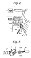
- the wire harness 1 as shown in FIG. 2, is arranged in a car body 8 of an automotive vehicle.
- a plurality of electric wires 2 are bundled in the main and branch line parts 4 and 5 and covered with sheath members 6 (FIG. 3), respectively.
- a measuring device 10 which serves to detect a trouble location in the wire harness 1, as shown in FIG. 1 comprises a pulse generating unit 11, a synchroscope 12, a computing unit 13, a memory 14, a display unit 15, and a pair of terminals 16A, 16B.
- the pulse generating unit 11 and synchroscope 12 are connected to the pair of terminals 16A, 16B while one terminal 16B is connected to the ground.
- the terminals 16A and 16B of the measuring device 10 is inserted into the connector 3 (any one of connectors 3A to 3E in FIG. 1) of the wire harness 1.
- the method of the present invention detects a trouble location of the electric wire 2 in the wire harness 1 by using the pulse radar method and the measuring device 10. This method for detecting the trouble location will be explained below.
- the pulse propagation time t can be measured by the synchroscope 22 in the measuring device 20. If the pulse propagation velocity v or the dielectric constant ⁇ is given beforehand, for example, if the pulse propagation velocity v is given by measuring the pulse propagation time t in a normal state and a line length, the distance L can be obtained from the pulse propagation velocity v and the measured value of the pulse propagation time t.
- the reflected wave Pb (solid line in FIG. 5) on the occasion of breakage has the same polarity as the transmitted wave Pa while the reflected wave Pb' (dotted line in FIG. 5) on the occasion of short circuit has the reverse polarity to the transmitted wave Pa. Accordingly, it is also possible to determine whether the trouble in the line is breakage or short circuit in accordance with the polarity of the reflected wave.
- the pulse radar method has been utilized in detection of a trouble point in an underground transmitting line and thus a principle of the pulse radar method has been known.
- the wire harness generally includes a number of electric wires provided in the main line part 4 and branch line part 5, as shown in FIG. 1 and particularly the electric wires branched from the main line 4 through the splice portions 2c. A particular device is required to effectively detect a trouble point in an electric wire having a splice portion 2c.
- the pulse width, period, and the like of the transmitting pulse may be preferably set, as shown in Table 1, in consideration of a pulse propagation velocity and a length of a wire harness, which can be known by means of actual measurement, a possible measuring range of a trouble location to be required, and the like.
- Table 1 Distance from a measuring point to a start point capable of measuring a trouble location Pulse width Period Duty ratio [cm] A [n sec] B [n sec] (A/B) 1 0.049 48.78 0.001 5 0.244 " 0.005 10 0.488 " 0.010 15 0.732 " 0.015 20 0.976 " 0.020
- the pulse radar method can compute the breakage location by dividing the products of the reflection time by the pulse propagation velocity into halves. Accordingly, in order to make the pulse propagation velocity known, the measuring device 20 measured the most standard cable (two parallel lines). Consequently, the pulse propagation velocity was 205 m/ ⁇ sec.
- the period B of the transmitted wave is set to be greater than the maximum of the pulse propagation time in the wire harness on the vehicle, since a lap between a reflected wave and a next transmitted wave will make the measurement difficult in the case where the above measurement is effected by transmitting a pulse wave at a certain period. Accordingly, assuming that the maximum length of the wire harness on the vehicle is 10 m, the period B of the transmitted wave will be 48.78 n sec by dividing 10 m by 205 m/ ⁇ sec.
- An electric wire parallel to a main line and a branch line is set as a sensing line for each electric wire 2 in the wire harness 1.
- the electric wire is set as a sensing line.
- the conditions are the fact that if the electric wire 2 has a splice portion 2c branching the main and branch lines, the measuring and sensing lines are juxtaposed to each other and the fact that the sensing line corresponding to one of the main and branch lines is independent of the other line.
- the measuring line W1 is a single line having no splice portion, as shown in FIG. 6(a), it is possible to detect a trouble location at a trouble point A by setting a line parallel to the measuring line W1 (a line on the same path as the measuring line W1) to be the sensing line W2 and by using the pulse radar method.
- the measuring line W1 has a splice portion, that is, if the measuring line W1 has a main line W10 and a splice line (branch line) W11 branched from the main line W10, it is possible to detect the trouble location at the trouble point F in the main line 10 by setting a line parallel with the main line W10 of the measuring line W1 as the sensing line W2, as shown in FIG. 6(b). It is also possible to detect the trouble location in the splice line W11 by setting a line parallel with the splice line W11 of the measuring line W1 as the sensing line W2, as shown in FIG. 6(c).
- the measuring line W1 has the main line W10 and the splice line W11 and the sensing line W2 has a main line W20 and a splice line W21 in the same path as the main line 10 and splice line W11 in the measuring line W1, it is difficult to detect the trouble location by the pulse radar method.
- the reason is as follows:
- a characteristic impedance R1 at a splice point P1 taken from an end side of the line path is given by the following equation (9), since a C capacitance and an L capacitance are changed to 2 times and 1/2 times, respectively.
- R1 (1/2) ⁇ L/C
- the reflection constant m is given as follows by the equation (7) mentioned above. That is, in the case where a pulse wave is transmitted from an end, a pulse wave reflected at the splice point P1 has a reversed polarity with respect to the transmitted pulse wave.
- the measuring device 10 receives the pulse waves reflected at the trouble point F, splice point P1 and terminal end of the splice line. Confusion of these reflected pulse waves will make it difficult to detect the trouble location at the trouble point.
- the measuring and sensing lines have splice portions, respectively, it is possible to detect the trouble location at the trouble point F in the main line W10 if branch positions and branch directions of the respective splice line.
- the circuit shown in FIG. 7 includes a first set of electric wires having a main line (a-a') and a splice line (d-d'), a second set of electric wires having a main line (b-b') and a splice line (e-e'), a third electric wire (c-c') having no splice portion, and a fourth electric wire (f-f') having no splice portion.
- the main lines (a-a', b-b') of the first and second sets of electric wires and the third electric wire (c-c') are arranged on a main line part between connectors 3A and 3B.
- the splice lines (d-d', e-e') of the first and second sets of electric wires extend to a connector 3C through a branch line part.
- the fourth electric wire (f-f') is arranged through the main and branch line parts between the connectors 3A and 3C.
- a line which meets the conditions shown in FIGS. 6(a) to 6(c) in compliance with a trouble section is set as a sensing line.
- Table 2 shows a relationship between the trouble section and the sensing line.
- an electric wire in association with the faulty electric wire (measuring line) is set as a sensing line beforehand.
- an arrangement of the wire harness 1 is set so that a sensing line corresponding to the measuring line exists in the wire harness 1.
- a sensing line for each electric wire 2 is set as a rule out of the other electric wires in the wire harness 1.
- An auxiliary electric wire for exclusive use of sensing may be assembled in a circuit construction of the wire harness, if desired.
- an auxiliary electric wire may be assembled in the branch line part so that the auxiliary electric wire passes through the branch line part in parallel with the one electric wire.
- the detection of a trouble location in the electric wire 2 in the wire harness 1 on an automotive vehicle is carried out by the following manners.
- any electrical equipments are brought into faultiness on account of a trouble in wire harnesses
- first of all the trouble wire harness 1 associated with the faulty is searched and then an electric wire 2 in trouble in the wire harness 1 is found by a tester.
- a connector or connectors on the wire harness 1 (at least a connector connected to the trouble electric wire) is detached from a mating connector.
- the trouble electric wire 2 is set to be a measuring line.
- the terminals 16A and 16B of the measuring device 10 are inserted into the connector so that the terminals 16A and 16B are connected to the measuring line and the sensing line corresponding to the measuring line.
- the pulse generating unit 11 in the device 10 transmits a pulse wave in a wire harness 1 as described above and the synchroscope 17 measures a time t in which a reflected wave turns back from a trouble point to the transmitting point.
- the computing unit 13 computes a distance L from the transmitting point to the trouble point by giving to the above equation (1) the time t and the known pulse propagation velocity v. Whether the trouble is breakage or short circuit can be judged on the basis of a polarity of the reflected wave with respect to that of the transmitted wave.
- the distance L, breakage, and short circuit are indicated on the display unit 15. An operator can know the trouble location from the distance L indicated on the display unit 15 and can readily repair the wire harness.
- the method of the present invention is effective in grasping a cause of trouble.
- each electric wire in the wire harness 1 may be set as each measuring line by exchanging a connection of the terminals 16A and 16B in order and the measuring device 10 may detect a trouble electric wire. It is also possible to automatically and effectively detect a trouble electric wire and a trouble location by providing a connector in the measuring device 10 and by coupling the connector to a connector for the wire harness 1.
- FIG. 8 shows another embodiment of a wire harness to be used in the method of the present invention.
- an end of each electric wire 2 in the wire harness is connected to each electrical wiring connectors 3A to 3E while a detecting electric wire 20 is branched in the vicinity of an end of each electric wire 2.
- a plurality of sets of the given number of electric wires 2 are connected to detecting connectors 21 independent of the electrical wiring connectors 3A to 3E, respectively.
- the detecting electric wires 20 are branched from six electric wires 2 in the vicinity of the connector 3A, respectively. Each set of three detecting electric wires 20 is connected to each detecting connectors 21. Further, the detecting electric wires 20 branched from three electric wires 2 near the connector 3B and the detecting electric wires 20 branched from three electric wires 20 near the connector 3E are connected to the respective detecting connector 21. The electric wires 2 in the mutual relationship between the measuring line and the sensing line are connected through the detecting electric wires 20 to the same detecting connector 21.
- detecting of the trouble location can be effected by the same manner of the first embodiment which uses the measuring device 10 in accordance with the pulse radar method. It will be easier than a conventional method to select connection portions for the terminals 16A and 16B of the measuring device 10 upon connecting the terminals 16A and 16B to the electric wires 2 to be set as the measuring and sensing lines, since each set of the given electric wires are connected to each detecting connector 21.
- FIG. 9 shows another embodiment of a wire harness to be used in the method of the present invention.
- an end of each electric wire 2 in the wire harness 1 is connected to each of the electrical wiring connectors 3A to 3E while detecting wiring 24 branched from a main wiring corresponding to each electric wire 2 are formed of bus bars or the like in a joint box 22 connected to the connector 3A or in wiring parts 23 provided in the connectors 3B and 3E.
- Terminals at ends of the wirings 24 are juxtaposed in pair in the joint box 22 and detecting connection parts provided in the connectors 3B and 3E.
- the detecting wirings 24 are constructed so that each pair of terminals become the respective measuring and sensing lines.
- the following steps are carried out: setting each of electric wires in a main line part and a branch line part of a wire harness as a sensing line, the electric wires being juxtaposed to each other in the main and branch line parts; setting an electric wire in trouble due to breakage or short circuit as a measuring line; transmitting a pulse wave in the measuring line and the sensing line corresponding to said measuring line at their ends; receiving a pulse wave reflected at a trouble point; measuring a difference in time between the transmitted pulse wave and the reflected pulse wave; and computing a distance from a measuring point to the trouble point in accordance with the difference in time and a signal propagation velocity. Accordingly, it is possible to easily and precisely detect the trouble location in the electric wire in the wire harness while maintaining the wire harness in a relatively simple construction by applying the pulse radar method to detection of the trouble location in the wire harness.
- the measuring line and the sensing line are juxtaposed to each other.
- the sensing line corresponding to the one electric wire is independent of the other electric wires.
- the sensing line is set to be an electric wire which meets the above conditions in the other electric wires except the measuring electric wire in the wire harness or in auxiliary sensing electric wires assembled in the wire harness.
- the wire harnesses are arranged so that a sensing line corresponding to each electric wire in a wire harness exists in the wire harness. Consequently, it is possible to effectively detect the trouble location in the wire harness while maintaining the wire harness in a simple construction and avoiding increase of a diameter of the wire harness.
Landscapes
- Engineering & Computer Science (AREA)
- Physics & Mathematics (AREA)
- General Physics & Mathematics (AREA)
- Computer Hardware Design (AREA)
- Microelectronics & Electronic Packaging (AREA)
- Chemical & Material Sciences (AREA)
- Combustion & Propulsion (AREA)
- Locating Faults (AREA)
- Testing Of Short-Circuits, Discontinuities, Leakage, Or Incorrect Line Connections (AREA)
Applications Claiming Priority (2)
| Application Number | Priority Date | Filing Date | Title |
|---|---|---|---|
| JP2332/96 | 1996-01-10 | ||
| JP00233296A JP3397957B2 (ja) | 1996-01-10 | 1996-01-10 | ワイヤーハーネスの故障位置検出方法及び同方法に用いるワイヤーハーネス |
Publications (2)
| Publication Number | Publication Date |
|---|---|
| EP0784209A2 true EP0784209A2 (fr) | 1997-07-16 |
| EP0784209A3 EP0784209A3 (fr) | 1998-04-15 |
Family
ID=11526365
Family Applications (1)
| Application Number | Title | Priority Date | Filing Date |
|---|---|---|---|
| EP97300018A Withdrawn EP0784209A3 (fr) | 1996-01-10 | 1997-01-02 | Méthode de détection de l'endroit d'un défaut dans un faisceau de câbles et faisceau de câble pour cela |
Country Status (3)
| Country | Link |
|---|---|
| US (1) | US5903156A (fr) |
| EP (1) | EP0784209A3 (fr) |
| JP (1) | JP3397957B2 (fr) |
Cited By (2)
| Publication number | Priority date | Publication date | Assignee | Title |
|---|---|---|---|---|
| EP0964256A1 (fr) * | 1998-06-10 | 1999-12-15 | Automobiles Peugeot | Procédé et dispositif de localisation des courts-circuits dans un bus d'un réseau de transmission d'informations multiplexé |
| CN104614636A (zh) * | 2015-02-28 | 2015-05-13 | 苏州路之遥科技股份有限公司 | 线束智能测试机微电脑找点工艺 |
Families Citing this family (20)
| Publication number | Priority date | Publication date | Assignee | Title |
|---|---|---|---|---|
| JP2000130244A (ja) * | 1998-10-26 | 2000-05-09 | Sanshin Ind Co Ltd | エンジン回転数表示装置 |
| DE19938060B4 (de) * | 1999-08-12 | 2008-06-19 | Nokia Siemens Networks Gmbh & Co.Kg | Integrierte Schaltung mit einer Testeinrichtung und Verfahren zum Testen der Güte elektrischer Verbindungen der ingegrierten Schaltung |
| CA2356068C (fr) * | 2000-09-30 | 2010-12-07 | Fluke Networks, Inc. | Instrument d'essai de reseau |
| JP2004062532A (ja) * | 2002-07-29 | 2004-02-26 | Renesas Technology Corp | 接続検証装置 |
| US6954076B2 (en) * | 2002-09-06 | 2005-10-11 | Northrop Grumman Corporation | Aircraft multi-function wire and insulation tester |
| US6833713B2 (en) | 2003-01-31 | 2004-12-21 | Delphi Technologies, Inc. | Smart wire harness for an electrical circuit |
| US7368919B2 (en) * | 2004-09-02 | 2008-05-06 | Ziota Technology Inc. | Wireless portable automated harness scanner system and method therefor |
| US7548801B2 (en) * | 2005-09-29 | 2009-06-16 | The United States Of America As Represented By The Secretary Of The Navy | Just in time wiring information system |
| EP2104863B1 (fr) | 2007-01-17 | 2010-05-05 | International Business Machines Corporation | Procédé de détermination de l'intégrité d'un chemin de retour de courant dans un dispositif électrique connecté ou pouvant être connecté à un autre dispositif |
| US7710121B2 (en) * | 2007-02-28 | 2010-05-04 | Federal Mogul Corporation | Electrical connector integrity tester |
| WO2010048385A1 (fr) * | 2008-10-22 | 2010-04-29 | Greenlee Textron Inc. | Procédé de réalisation d'un essai d'intégrité de blindage et procédé d'isolation de défaut dans un blindage à l'aide d'une analyse graphique |
| US8164433B2 (en) * | 2009-04-17 | 2012-04-24 | Ac Propulsion, Inc. | Detecting faults in a wiring harness |
| US8494706B2 (en) | 2011-08-19 | 2013-07-23 | Federal-Mogul Corporation | Electric fuel pump tester and method |
| JP5765161B2 (ja) * | 2011-09-16 | 2015-08-19 | 日立金属株式会社 | 差動信号伝送用ケーブルの特性評価機構及び特性評価方法 |
| US20150212025A1 (en) * | 2014-01-30 | 2015-07-30 | Caterpillar Inc. | Harness Diagnostics System for a Machine |
| JP6374894B2 (ja) * | 2016-02-02 | 2018-08-15 | 矢崎総業株式会社 | 車両用回路体 |
| JP6353858B2 (ja) * | 2016-02-22 | 2018-07-04 | 矢崎総業株式会社 | ワイヤハーネス構造 |
| DE102016210601A1 (de) * | 2016-06-15 | 2017-12-21 | Leoni Kabel Gmbh | Verfahren zur Überwachung einer Leitung und Messanordnung mit einer Leitung |
| JP6652036B2 (ja) * | 2016-11-07 | 2020-02-19 | 株式会社オートネットワーク技術研究所 | ワイヤーハーネス及びワイヤーハーネスの製造方法 |
| FR3066825B1 (fr) * | 2017-05-29 | 2019-07-19 | Dcns | Systeme de reflectometrie pour la detection de defaut sur un connecteur multipoints durci d'un reseau electrique |
Citations (1)
| Publication number | Priority date | Publication date | Assignee | Title |
|---|---|---|---|---|
| JPH0422311A (ja) | 1990-05-17 | 1992-01-27 | Matsushita Electric Ind Co Ltd | 電気湯沸し器 |
Family Cites Families (7)
| Publication number | Priority date | Publication date | Assignee | Title |
|---|---|---|---|---|
| GB2097214B (en) * | 1981-04-03 | 1985-02-06 | Gen Electric Plc | Locating faults in power transmission systems |
| US4538103A (en) * | 1982-08-30 | 1985-08-27 | John Cappon | Time domain reflectometer apparatus for identifying the location of cable defects |
| US4859953A (en) * | 1988-07-08 | 1989-08-22 | General Motors Corporation | Modular test assembly for wiring harnesses |
| US5264796A (en) * | 1990-04-03 | 1993-11-23 | Ford Motor Company | Fault detection and isolation in automotive wiring harness including dedicated test line |
| US5066919A (en) * | 1990-04-03 | 1991-11-19 | Ford Motor Company | Fault detection and isolation in automotive wiring harness by network analysis method |
| US5268644A (en) * | 1990-04-03 | 1993-12-07 | Ford Motor Company | Fault detection and isolation in automotive wiring harness by time-domain reflectometry |
| US5206595A (en) * | 1991-09-10 | 1993-04-27 | Electric Power Research Institute | Advanced cable fault location |
-
1996
- 1996-01-10 JP JP00233296A patent/JP3397957B2/ja not_active Expired - Fee Related
- 1996-12-27 US US08/774,885 patent/US5903156A/en not_active Expired - Fee Related
-
1997
- 1997-01-02 EP EP97300018A patent/EP0784209A3/fr not_active Withdrawn
Patent Citations (1)
| Publication number | Priority date | Publication date | Assignee | Title |
|---|---|---|---|---|
| JPH0422311A (ja) | 1990-05-17 | 1992-01-27 | Matsushita Electric Ind Co Ltd | 電気湯沸し器 |
Cited By (3)
| Publication number | Priority date | Publication date | Assignee | Title |
|---|---|---|---|---|
| EP0964256A1 (fr) * | 1998-06-10 | 1999-12-15 | Automobiles Peugeot | Procédé et dispositif de localisation des courts-circuits dans un bus d'un réseau de transmission d'informations multiplexé |
| FR2779828A1 (fr) * | 1998-06-10 | 1999-12-17 | Peugeot | Procede de localisation des courts-circuits dans au moins un bus d'un reseau de transmission d'informations multiplexe et dispositif de diagnostic mettant en oeuvre le procede |
| CN104614636A (zh) * | 2015-02-28 | 2015-05-13 | 苏州路之遥科技股份有限公司 | 线束智能测试机微电脑找点工艺 |
Also Published As
| Publication number | Publication date |
|---|---|
| EP0784209A3 (fr) | 1998-04-15 |
| JP3397957B2 (ja) | 2003-04-21 |
| JPH09189739A (ja) | 1997-07-22 |
| US5903156A (en) | 1999-05-11 |
Similar Documents
| Publication | Publication Date | Title |
|---|---|---|
| US5903156A (en) | Method for detecting trouble location in wire harnesses and wire harness to be used in the method | |
| EP0784210B1 (fr) | Appareil pour détecter l'endroit d'un défaut dans un faisceau de câbles | |
| US5268644A (en) | Fault detection and isolation in automotive wiring harness by time-domain reflectometry | |
| EP0629866B1 (fr) | Méthode pour localiser des défauts dans un câble électrique de puissance | |
| US4690475A (en) | Computer harness adaptive tester | |
| EP1395840B1 (fr) | Systeme et procede de detection d'anomalies | |
| US5029274A (en) | Apparatus and method for testing the integrity of wiring ensembles | |
| US20040023560A1 (en) | Apparatus and method for a reversible emulator/target cable connector | |
| US20070279071A1 (en) | Method and System for Diagnosing Degradation in Vehicle Wiring | |
| CN1239914C (zh) | 线缆故障监测系统 | |
| CN103109198B (zh) | 通过反射法检测电缺陷的方法和结构 | |
| US5264796A (en) | Fault detection and isolation in automotive wiring harness including dedicated test line | |
| KR100310971B1 (ko) | 와이어 하네스 시험방법 및 이를 수행하기 위한 시스템 | |
| EP0294159B1 (fr) | Système détecteur ramifié | |
| EP0735373A1 (fr) | Méthode et appareil pour mesurer l'impédance de transfert d'organes blindés et des courants de mode commun dans des blindages | |
| US5679987A (en) | Method and device for obtaining connectivity information of telecommunication facilities | |
| US4931741A (en) | Branched sensor system | |
| JPH04132180A (ja) | コネクタ | |
| JPS6317015Y2 (fr) | ||
| US20210364576A1 (en) | Use of Standing Wave Ratio Measurements for Interconnect Testing | |
| JPS5819569A (ja) | 心線対照装置 | |
| JPH05180892A (ja) | 複数導線の導通検査方法および装置 | |
| SU1379841A1 (ru) | Устройство контрол подключени кабелей | |
| JPH07280864A (ja) | 導通検査方法及び導通検査装置 | |
| JPH06207964A (ja) | 部分放電検出装置 |
Legal Events
| Date | Code | Title | Description |
|---|---|---|---|
| PUAI | Public reference made under article 153(3) epc to a published international application that has entered the european phase |
Free format text: ORIGINAL CODE: 0009012 |
|
| 17P | Request for examination filed |
Effective date: 19970123 |
|
| AK | Designated contracting states |
Kind code of ref document: A2 Designated state(s): DE FR GB |
|
| PUAL | Search report despatched |
Free format text: ORIGINAL CODE: 0009013 |
|
| AK | Designated contracting states |
Kind code of ref document: A3 Designated state(s): DE FR GB |
|
| 17Q | First examination report despatched |
Effective date: 20060908 |
|
| STAA | Information on the status of an ep patent application or granted ep patent |
Free format text: STATUS: THE APPLICATION IS DEEMED TO BE WITHDRAWN |
|
| 18D | Application deemed to be withdrawn |
Effective date: 20070119 |