EP0784355A1 - Verbindungsanordnung für elektrisches Gerät, insbesondere für ein verbindungsblockartiges Gerät, und ein mit solcher Anordnung ausgerüstetes Gehäuse - Google Patents
Verbindungsanordnung für elektrisches Gerät, insbesondere für ein verbindungsblockartiges Gerät, und ein mit solcher Anordnung ausgerüstetes Gehäuse Download PDFInfo
- Publication number
- EP0784355A1 EP0784355A1 EP96402744A EP96402744A EP0784355A1 EP 0784355 A1 EP0784355 A1 EP 0784355A1 EP 96402744 A EP96402744 A EP 96402744A EP 96402744 A EP96402744 A EP 96402744A EP 0784355 A1 EP0784355 A1 EP 0784355A1
- Authority
- EP
- European Patent Office
- Prior art keywords
- bars
- housing
- interconnection
- arrangement
- electrical
- Prior art date
- Legal status (The legal status is an assumption and is not a legal conclusion. Google has not performed a legal analysis and makes no representation as to the accuracy of the status listed.)
- Granted
Links
- 239000004020 conductor Substances 0.000 claims abstract description 10
- 239000011810 insulating material Substances 0.000 description 2
- 239000002184 metal Substances 0.000 description 2
- 230000000694 effects Effects 0.000 description 1
- 238000009434 installation Methods 0.000 description 1
- 230000035515 penetration Effects 0.000 description 1
- 238000003466 welding Methods 0.000 description 1
Images


Classifications
-
- H—ELECTRICITY
- H01—ELECTRIC ELEMENTS
- H01R—ELECTRICALLY-CONDUCTIVE CONNECTIONS; STRUCTURAL ASSOCIATIONS OF A PLURALITY OF MUTUALLY-INSULATED ELECTRICAL CONNECTING ELEMENTS; COUPLING DEVICES; CURRENT COLLECTORS
- H01R9/00—Structural associations of a plurality of mutually-insulated electrical connecting elements, e.g. terminal strips or terminal blocks; Terminals or binding posts mounted upon a base or in a case; Bases therefor
- H01R9/22—Bases, e.g. strip, block, panel
- H01R9/24—Terminal blocks
- H01R9/26—Clip-on terminal blocks for side-by-side rail- or strip-mounting
- H01R9/2675—Electrical interconnections between two blocks, e.g. by means of busbars
Definitions
- the invention relates to an interconnection arrangement for connecting bars between terminals for electrical equipment and in particular for equipment of the electrical terminal block type. It also relates to switchgear boxes fitted with such an arrangement.
- connection terminals which are designed to receive electrical conductors and which are selectively interconnected by connecting conductive bars.
- Such arrangements are in particular provided in the apparatuses, of the electrical terminal block type, where the terminals and the bars are housed and fixed in containers made of molded insulating material comprising openings giving access to the terminals from the outside of the containers.
- connection terminals are arranged in a staggered manner on either side on, for example, two opposite sides of a housing serving as a container.
- Connection bars interconnect terminals which are arranged on either side of the housing and for example terminals situated on the same level.
- the invention therefore proposes an interconnection arrangement for connecting bars between terminals of an apparatus electrical, in particular for apparatus of the electrical terminal block type, comprising connection terminals for electrical conductors which are arranged in a stepped manner on different sides of a housing and which are electrically and selectively interconnected by conductive connection bars at least partially arranged on different floor levels in the housing.
- the arrangement comprises at least two bars to be interconnected which, fixed, each comprise at least one projection made opposite a corresponding projection disposed on the other bar and at least one interconnection piece conductive, preferably of the rod or blade type, the ends of which each form a clamp allowing it to be positioned on one of the projections facing the bars to be interconnected.
- the interconnection piece has gripper ends having their respective openings which are arranged laterally and which open in the same direction so as to come to straddle the projections opposite the bars on the same side. that they interconnect.
- the interconnection piece has clamp ends having their respective openings which are arranged laterally and which open in two opposite directions.
- the invention also provides an electrical switchgear box, in particular of the terminal block type, comprising connection terminals for electrical conductors which are arranged in a staggered manner on different sides of a box and which are electrically and selectively interconnected by of connecting bars of different floor levels in the case.
- this box comprises at least one interconnection arrangement as characterized above.
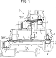
- Figures 1 and 2 show an example of the same electrical terminal block housing having an interconnection arrangement according to the invention, in front view and in perspective.
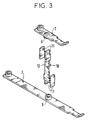
- Figure 3 shows an exploded view of an interconnection arrangement according to the invention.
- FIG. 4 shows a partial front view of a variant of a terminal block housing comprising an interconnection arrangement according to the invention.
- FIG. 5 presents a partial perspective view of the arrangement presented in FIG. 4.
- FIG. 6 presents a perspective view of the interconnection piece according to the variant presented in FIGS. 4 and 5.
- FIGS. 1 and 2 The example of an electrical terminal block presented in FIGS. 1 and 2 is conventionally composed of a housing 1, generally molded in an insulating material which is for example of a type similar to that described in French patent 2708385 or even in French patent 2,513,437.
- This box 1 comprises housings 2 making it possible to receive electrical connection terminals 3 for conductors 4, here external to the box.
- These terminals are shown here arranged on two stages and on two opposite sides of the housing 1, they are assumed to be of the screw type and each composed of a bracket 5 into which it is possible to introduce an electrical conductor, of the type single-strand or multi-strand rod or wire, between a wedging jaw 6 of this stirrup and an end portion of a bar 7 which the stirrup overlaps, as can be seen in particular for the terminal at the bottom right of the figure 1.
- a housing 2 is here provided for each terminal 3, it opens towards the outside of the housing 1 so as to allow the penetration of a conductor to be connected to a terminal between the bracket of this terminal and the bar on which this caliper is placed.
- the respective stirrups of the terminals are assumed to be movable in translation relative to the bars on which they are placed in the housings provided for these terminals. These movements are provided for by maneuvering screws 8 which are associated with the stirrups and which bear on the bars, according to a widely known arrangement.
- the bars 7 presented here are assumed to be made of a suitably conductive metal and are designed to each make an interconnection between at least two terminals.
- each of the two bars shown is assumed to be fixed and connected to two terminals which are arranged on two opposite sides of a housing and practically at the same level of floor relative to the base of the housing shown here.
- each projection 9 is for example of cylindrical shape, for example being obtained by mechanical deformation or local cutting of the bar in the area concerned.
- the interconnection piece 10 is here shaped so as to be able to cooperate with the two projections which are here assumed to be respectively positioned face to face, each on one of the two bars to be interconnected.
- each clamp 11 comprises two flat and parallel parts which project perpendicularly from the same third part 12 and which are spaced from one another by an interval corresponding to the diameter of a projection for the area of this projection where an end clamp is likely to be placed.
- the two clamps 11 of an interconnection piece are provided on the same side of this part and open in the same direction so as to straddle the projections 9 on the same side opposite the bars they interconnect.
- the interconnection piece is preferably supported on at least one of the two walls carrying the two projections each facing a bar, as well as against a bottom wall 11 of the housing 1 by the two ends of each of its two clamps.
- the two clamps 11 of an interconnection piece 10 are each provided on an opposite side of this piece and therefore open in diametrically opposite directions.
- the interconnection piece bears on at least one of the two walls carrying the two projections each facing a bar, as well as against the bottom wall 11 of the housing 1 by the two ends of one of its two clamps, the two ends of the other being capable of receiving the wall (not shown here) of the cover or of a box closing the opening opening on the side of the box which is opposite the bottom 11.
- FIG. 4 presents a partial view of a terminal block housing 1 ′ comprising an alternative interconnection arrangement according to the invention.
- This box 1 ' has housings, such as 2', making it possible to receive electrical connection terminals 3 'for conductors external to the box.
- These terminals are here assumed to be of the same type as the terminals 3 mentioned above and they therefore each cooperate with a strip 7 'functionally identical to a strip 7.
- the strips 7' to be interconnected each have a projection 9 'or 9''provided for cooperate with an interconnection piece 10 '.
- the interconnection piece 10 ′ is here supposed to be constituted by a metal blade initially of elongated rectangular shape whose two ends are split longitudinally and folded on the same side, here practically at an angle law.
- clamps 11 ' which are arranged laterally and which open in the same direction so as to straddle corresponding projections on the same side and here aligned opposite each other by two bars 7' to be interconnected, as shown in Figures 4 and 5.
- the projections provided on the bars are likely to be one and / or the other formed (s) so as to be presented either in the form of a truly projecting part, such as 9 ′, obtained by cutting and folding, or under the shape of a bar part oriented in the same way as the projection of the other bar, this part preferably being between elbows of the bar which comprises it, such as the part 9 ''.
- Such a positioning between two bar elbows of the part, such as 9 '', which is laterally gripped by one of the clamps 11 'of an interconnection piece 10' makes it possible to avoid the longitudinal sliding of this piece of interconnection on the bar and then participates in the immobilization of this part in the interconnection position.
- this partial immobilization function performed by a set of two elbows each produced on one of the bars for the projection carried by this bar or possibly by one or more internal reliefs of the housing.
- the pinching effect exerted by an interconnection piece on the projections on which it comes to be positioned is preferably provided to allow this piece to hold itself in position between the bars that it interconnects.
Landscapes
- Connections Arranged To Contact A Plurality Of Conductors (AREA)
- Connection Or Junction Boxes (AREA)
- Connector Housings Or Holding Contact Members (AREA)
Applications Claiming Priority (3)
| Application Number | Priority Date | Filing Date | Title |
|---|---|---|---|
| FR9600210 | 1996-01-10 | ||
| FR9600210A FR2743448B1 (fr) | 1996-01-10 | 1996-01-10 | Agencement d'interconnexion pour appareillage electrique, notamment pour appareillage de type bloc de jonction, et boitier equipe d'un tel agencement |
| US08/780,541 US5848917A (en) | 1996-01-10 | 1997-01-09 | Interconnection assembly of electrical equipment, in particular for junction block type equipment, and a housing fitted with such an assembly |
Publications (2)
| Publication Number | Publication Date |
|---|---|
| EP0784355A1 true EP0784355A1 (de) | 1997-07-16 |
| EP0784355B1 EP0784355B1 (de) | 1999-09-22 |
Family
ID=26232429
Family Applications (1)
| Application Number | Title | Priority Date | Filing Date |
|---|---|---|---|
| EP96402744A Expired - Lifetime EP0784355B1 (de) | 1996-01-10 | 1996-12-16 | Verbindungsanordnung für elektrisches Gerät, insbesondere für ein verbindungsblockartiges Gerät, und ein mit solcher Anordnung ausgerüstetes Gehäuse |
Country Status (5)
| Country | Link |
|---|---|
| US (1) | US5848917A (de) |
| EP (1) | EP0784355B1 (de) |
| DE (1) | DE69604376T2 (de) |
| ES (1) | ES2138310T3 (de) |
| FR (1) | FR2743448B1 (de) |
Cited By (4)
| Publication number | Priority date | Publication date | Assignee | Title |
|---|---|---|---|---|
| EP1758206A2 (de) | 2005-08-26 | 2007-02-28 | Phoenix Contact GmbH & Co. KG | Vertikale Steckmöglichkeit bei Reihenklemme mit Etagenversatz |
| EP2105995A1 (de) * | 2008-03-27 | 2009-09-30 | Cabur S.r.l. | Verbesserte Steckervorrichtung, Methode und elektrische Verbindungsvorrichtung dafür |
| EP1976064A3 (de) * | 2007-03-29 | 2012-01-04 | Weidmüller Interface GmbH & Co. KG | Rangierverteilerklemmensystem |
| CN109346863A (zh) * | 2018-10-11 | 2019-02-15 | 南京多特蒙电气有限公司 | 一种双层导通的每层双桥接导轨端子 |
Families Citing this family (15)
| Publication number | Priority date | Publication date | Assignee | Title |
|---|---|---|---|---|
| FR2757316B1 (fr) * | 1996-12-16 | 1999-01-22 | Entrelec Sa | Module de raccordement a bornes de connexion interconnectables par piece(s) conductrice(s) mobile(s) |
| FR2873501B1 (fr) * | 2004-07-23 | 2006-10-13 | Hager Electro S A S Soc Par Ac | Boitier modulaire a cablage traversant |
| DE202006017882U1 (de) * | 2006-11-22 | 2007-03-01 | Cedes Ag | Steckmodul |
| USD634713S1 (en) | 2008-04-14 | 2011-03-22 | Finder S.P.A. | Sockets for relays |
| USD626516S1 (en) * | 2009-04-29 | 2010-11-02 | Phoenix Contact Gmbh & Co. Kg | Adjusting device for the setpoint of an electric module |
| DE202010005557U1 (de) * | 2010-06-04 | 2011-10-31 | Weidmüller Interface GmbH & Co. KG | Rangierklemme in Etagenbauform |
| DE102010033808B4 (de) * | 2010-08-09 | 2016-12-22 | Phoenix Contact Gmbh & Co. Kg | Reihenklemme |
| JP5914094B2 (ja) * | 2012-03-29 | 2016-05-11 | 株式会社サンコーシヤ | 保安器のdinレールへの取付装置 |
| USD700898S1 (en) * | 2012-07-31 | 2014-03-11 | Phoenix Contact Gmbh & Co. Kg | Socket module for an electronic relay |
| USD765039S1 (en) * | 2014-04-16 | 2016-08-30 | Weidmueller Interface Gmbh & Co. Kg | Terminal block |
| DE102014115048A1 (de) * | 2014-10-16 | 2016-04-21 | Phoenix Contact Gmbh & Co. Kg | Klemmeneinrichtung mit einer Stromschiene |
| JP1558910S (de) * | 2016-02-29 | 2016-09-20 | ||
| JP6992621B2 (ja) * | 2018-03-14 | 2022-01-13 | オムロン株式会社 | 接続子およびソケット |
| DE102021101342A1 (de) * | 2021-01-22 | 2022-07-28 | Phoenix Contact Gmbh & Co. Kg | Brückungselement, Anschlusselement und elektronisches Gerät |
| DE102022118427A1 (de) * | 2022-07-22 | 2024-01-25 | WAGO Verwaltungsgesellschaft mit beschränkter Haftung | Federkraftklemmanschluss, Leiteranschlussklemme und Verfahren zur Herstellung eines Federkraftklemmanschlusses |
Citations (6)
| Publication number | Priority date | Publication date | Assignee | Title |
|---|---|---|---|---|
| GB1068233A (en) * | 1963-10-02 | 1967-05-10 | Gottfried Glasel | Improvements in and relating to neutral conductor terminal units and terminal blocks |
| GB1240984A (en) * | 1969-09-09 | 1971-07-28 | Klippon Electricals Ltd | Terminal block |
| FR2513437A1 (fr) | 1981-09-21 | 1983-03-25 | Alsthom Cgee | Bloc de jonction a cartouche fusible et lampe-temoin |
| GB2155252A (en) * | 1984-03-02 | 1985-09-18 | Amp Inc | Power distribution unit for modular wall panels |
| EP0388058A1 (de) * | 1989-03-17 | 1990-09-19 | Yazaki Corporation | Stromschiene als Zwischenschicht in einer Steckvorrichtung |
| FR2708385A1 (fr) | 1993-07-28 | 1995-02-03 | Entrelec Sa | Bloc de jonction électrique. |
Family Cites Families (1)
| Publication number | Priority date | Publication date | Assignee | Title |
|---|---|---|---|---|
| US5147218A (en) * | 1991-04-12 | 1992-09-15 | Minnesota Mining And Manufacturing Company | Pluggable modular splicing connector and bridging adapter |
-
1996
- 1996-01-10 FR FR9600210A patent/FR2743448B1/fr not_active Expired - Fee Related
- 1996-12-16 DE DE69604376T patent/DE69604376T2/de not_active Expired - Lifetime
- 1996-12-16 ES ES96402744T patent/ES2138310T3/es not_active Expired - Lifetime
- 1996-12-16 EP EP96402744A patent/EP0784355B1/de not_active Expired - Lifetime
-
1997
- 1997-01-09 US US08/780,541 patent/US5848917A/en not_active Expired - Fee Related
Patent Citations (6)
| Publication number | Priority date | Publication date | Assignee | Title |
|---|---|---|---|---|
| GB1068233A (en) * | 1963-10-02 | 1967-05-10 | Gottfried Glasel | Improvements in and relating to neutral conductor terminal units and terminal blocks |
| GB1240984A (en) * | 1969-09-09 | 1971-07-28 | Klippon Electricals Ltd | Terminal block |
| FR2513437A1 (fr) | 1981-09-21 | 1983-03-25 | Alsthom Cgee | Bloc de jonction a cartouche fusible et lampe-temoin |
| GB2155252A (en) * | 1984-03-02 | 1985-09-18 | Amp Inc | Power distribution unit for modular wall panels |
| EP0388058A1 (de) * | 1989-03-17 | 1990-09-19 | Yazaki Corporation | Stromschiene als Zwischenschicht in einer Steckvorrichtung |
| FR2708385A1 (fr) | 1993-07-28 | 1995-02-03 | Entrelec Sa | Bloc de jonction électrique. |
Cited By (6)
| Publication number | Priority date | Publication date | Assignee | Title |
|---|---|---|---|---|
| EP1758206A2 (de) | 2005-08-26 | 2007-02-28 | Phoenix Contact GmbH & Co. KG | Vertikale Steckmöglichkeit bei Reihenklemme mit Etagenversatz |
| US7192316B1 (en) | 2005-08-26 | 2007-03-20 | Phoenix Contact Gmbh & Co., Kg | Electrical connecting terminal |
| EP1758206A3 (de) * | 2005-08-26 | 2012-01-25 | Phoenix Contact GmbH & Co. KG | Vertikale Steckmöglichkeit bei Reihenklemme mit Etagenversatz |
| EP1976064A3 (de) * | 2007-03-29 | 2012-01-04 | Weidmüller Interface GmbH & Co. KG | Rangierverteilerklemmensystem |
| EP2105995A1 (de) * | 2008-03-27 | 2009-09-30 | Cabur S.r.l. | Verbesserte Steckervorrichtung, Methode und elektrische Verbindungsvorrichtung dafür |
| CN109346863A (zh) * | 2018-10-11 | 2019-02-15 | 南京多特蒙电气有限公司 | 一种双层导通的每层双桥接导轨端子 |
Also Published As
| Publication number | Publication date |
|---|---|
| US5848917A (en) | 1998-12-15 |
| DE69604376T2 (de) | 2000-01-05 |
| EP0784355B1 (de) | 1999-09-22 |
| FR2743448B1 (fr) | 1998-02-13 |
| FR2743448A1 (fr) | 1997-07-11 |
| DE69604376D1 (de) | 1999-10-28 |
| ES2138310T3 (es) | 2000-01-01 |
Similar Documents
| Publication | Publication Date | Title |
|---|---|---|
| EP0784355B1 (de) | Verbindungsanordnung für elektrisches Gerät, insbesondere für ein verbindungsblockartiges Gerät, und ein mit solcher Anordnung ausgerüstetes Gehäuse | |
| EP0470887A1 (de) | Elektrischer Abzweigverbinder | |
| EP0005087A1 (de) | Verbindungszubehörsystem für Stromschiene mit asymmetrischem Profil | |
| EP0237388B1 (de) | Speise- oder Überbrückungsgerät für nebeneinander stehende elektrische Einrichtungen | |
| FR2766628A1 (fr) | Peigne d'interconnexion pour alignement de bornes de raccordement electrique d'un appareillage et module(s) de logement d'appareillage correspondant(s) | |
| CA2067080C (fr) | Agencement de connexion pour fils electrique et piece de connexion pour un tel agencement | |
| FR2766297A1 (fr) | Appareil electrique portant un support de contact fixe et une borne de raccordement | |
| EP3409084B1 (de) | Kabelbaumanschlussplatte | |
| FR2700075A1 (fr) | Adaptateur pour relier des appareils, des lignes d'alimentation et/ou de dérivation à des barres omnibus d'un jeu de barres. | |
| FR2757316A1 (fr) | Module de raccordement a bornes de connexion interconnectables par piece(s) conductrice(s) mobile(s) | |
| WO2004030170A2 (fr) | Dispositif de fixation et de contact pour barres de bus | |
| EP0478469A1 (de) | Nulleiter- und Erdanschlussklemmen in einem elektrischen Verteilerkasten | |
| EP0704874B1 (de) | Differentialschutzschalter zugeordnet zu einem oder mehreren Schaltungsschutzelementen wie Schmelzsicherungen oder Schutzschalter | |
| EP2503644B1 (de) | Elektrogerät von Klemmenleiste Typ | |
| FR2708385A1 (fr) | Bloc de jonction électrique. | |
| FR3020189A3 (fr) | Kit pour terminaisons de cables servant a connecter une installation de distribution electrique a un cable haute tension | |
| FR2495392A1 (fr) | Support de barres collectrices, notamment pour armoires electriques de distribution | |
| FR2566970A1 (fr) | Borne de raccordement pour plaques conductrices | |
| EP0817318A1 (de) | Anschlussbuchse für Kammformige Sammelschiene insbesondere für modulare elektrische Geräte | |
| FR2990293A1 (fr) | Disjoncteur a borne de branchement orientable | |
| FR2597664A1 (fr) | Dispositif de connexion electrique du type a perforation d'isolant | |
| EP0848450A1 (de) | Anschlussvorrichtung von elektrischen Kabel mit ein oder einer Mehrzahl vom Leitern | |
| FR2815178A1 (fr) | Dispositif de connexion destine a un coffret de branchement electrique et a un distributeur electrique | |
| FR2646566A1 (fr) | Embout de cablage pour le raccordement d'un cable electrique a une borne d'appareil | |
| EP1353408B1 (de) | Elektrische Sammelschiene |
Legal Events
| Date | Code | Title | Description |
|---|---|---|---|
| PUAI | Public reference made under article 153(3) epc to a published international application that has entered the european phase |
Free format text: ORIGINAL CODE: 0009012 |
|
| AK | Designated contracting states |
Kind code of ref document: A1 Designated state(s): DE ES FR GB IT |
|
| 17P | Request for examination filed |
Effective date: 19970903 |
|
| GRAG | Despatch of communication of intention to grant |
Free format text: ORIGINAL CODE: EPIDOS AGRA |
|
| 17Q | First examination report despatched |
Effective date: 19981207 |
|
| GRAG | Despatch of communication of intention to grant |
Free format text: ORIGINAL CODE: EPIDOS AGRA |
|
| GRAG | Despatch of communication of intention to grant |
Free format text: ORIGINAL CODE: EPIDOS AGRA |
|
| GRAH | Despatch of communication of intention to grant a patent |
Free format text: ORIGINAL CODE: EPIDOS IGRA |
|
| GRAH | Despatch of communication of intention to grant a patent |
Free format text: ORIGINAL CODE: EPIDOS IGRA |
|
| GRAA | (expected) grant |
Free format text: ORIGINAL CODE: 0009210 |
|
| AK | Designated contracting states |
Kind code of ref document: B1 Designated state(s): DE ES FR GB IT |
|
| ITF | It: translation for a ep patent filed | ||
| GBT | Gb: translation of ep patent filed (gb section 77(6)(a)/1977) |
Effective date: 19990927 |
|
| REF | Corresponds to: |
Ref document number: 69604376 Country of ref document: DE Date of ref document: 19991028 |
|
| REG | Reference to a national code |
Ref country code: ES Ref legal event code: FG2A Ref document number: 2138310 Country of ref document: ES Kind code of ref document: T3 |
|
| PLBE | No opposition filed within time limit |
Free format text: ORIGINAL CODE: 0009261 |
|
| STAA | Information on the status of an ep patent application or granted ep patent |
Free format text: STATUS: NO OPPOSITION FILED WITHIN TIME LIMIT |
|
| 26N | No opposition filed | ||
| REG | Reference to a national code |
Ref country code: GB Ref legal event code: IF02 |
|
| REG | Reference to a national code |
Ref country code: FR Ref legal event code: CJ Ref country code: FR Ref legal event code: CD Ref country code: FR Ref legal event code: CA |
|
| PGFP | Annual fee paid to national office [announced via postgrant information from national office to epo] |
Ref country code: ES Payment date: 20091222 Year of fee payment: 14 |
|
| PGFP | Annual fee paid to national office [announced via postgrant information from national office to epo] |
Ref country code: IT Payment date: 20091223 Year of fee payment: 14 Ref country code: GB Payment date: 20091218 Year of fee payment: 14 |
|
| GBPC | Gb: european patent ceased through non-payment of renewal fee |
Effective date: 20101216 |
|
| PG25 | Lapsed in a contracting state [announced via postgrant information from national office to epo] |
Ref country code: GB Free format text: LAPSE BECAUSE OF NON-PAYMENT OF DUE FEES Effective date: 20101216 |
|
| PG25 | Lapsed in a contracting state [announced via postgrant information from national office to epo] |
Ref country code: IT Free format text: LAPSE BECAUSE OF NON-PAYMENT OF DUE FEES Effective date: 20101216 |
|
| REG | Reference to a national code |
Ref country code: ES Ref legal event code: FD2A Effective date: 20120206 |
|
| PG25 | Lapsed in a contracting state [announced via postgrant information from national office to epo] |
Ref country code: ES Free format text: LAPSE BECAUSE OF NON-PAYMENT OF DUE FEES Effective date: 20101217 |
|
| PGFP | Annual fee paid to national office [announced via postgrant information from national office to epo] |
Ref country code: DE Payment date: 20121220 Year of fee payment: 17 |
|
| REG | Reference to a national code |
Ref country code: DE Ref legal event code: R119 Ref document number: 69604376 Country of ref document: DE |
|
| REG | Reference to a national code |
Ref country code: DE Ref legal event code: R119 Ref document number: 69604376 Country of ref document: DE Effective date: 20140701 |
|
| PG25 | Lapsed in a contracting state [announced via postgrant information from national office to epo] |
Ref country code: DE Free format text: LAPSE BECAUSE OF NON-PAYMENT OF DUE FEES Effective date: 20140701 |
|
| REG | Reference to a national code |
Ref country code: FR Ref legal event code: PLFP Year of fee payment: 20 |
|
| PGFP | Annual fee paid to national office [announced via postgrant information from national office to epo] |
Ref country code: FR Payment date: 20151221 Year of fee payment: 20 |