EP0785060A2 - Procédé de moulage par injection - Google Patents
Procédé de moulage par injection Download PDFInfo
- Publication number
- EP0785060A2 EP0785060A2 EP97100085A EP97100085A EP0785060A2 EP 0785060 A2 EP0785060 A2 EP 0785060A2 EP 97100085 A EP97100085 A EP 97100085A EP 97100085 A EP97100085 A EP 97100085A EP 0785060 A2 EP0785060 A2 EP 0785060A2
- Authority
- EP
- European Patent Office
- Prior art keywords
- workpieces
- carrier system
- workpiece carrier
- phase
- tool
- Prior art date
- Legal status (The legal status is an assumption and is not a legal conclusion. Google has not performed a legal analysis and makes no representation as to the accuracy of the status listed.)
- Granted
Links
- 238000001746 injection moulding Methods 0.000 title claims description 24
- 238000000034 method Methods 0.000 claims abstract description 20
- 230000000694 effects Effects 0.000 claims description 3
- 238000007689 inspection Methods 0.000 claims description 2
- 238000002347 injection Methods 0.000 abstract description 3
- 239000007924 injection Substances 0.000 abstract description 3
- 238000000465 moulding Methods 0.000 abstract 4
- 238000000605 extraction Methods 0.000 abstract 1
- 238000010137 moulding (plastic) Methods 0.000 abstract 1
- 230000007257 malfunction Effects 0.000 description 2
- 238000010586 diagram Methods 0.000 description 1
- 238000007493 shaping process Methods 0.000 description 1
- 230000000007 visual effect Effects 0.000 description 1
Images


Classifications
-
- B—PERFORMING OPERATIONS; TRANSPORTING
- B29—WORKING OF PLASTICS; WORKING OF SUBSTANCES IN A PLASTIC STATE IN GENERAL
- B29C—SHAPING OR JOINING OF PLASTICS; SHAPING OF MATERIAL IN A PLASTIC STATE, NOT OTHERWISE PROVIDED FOR; AFTER-TREATMENT OF THE SHAPED PRODUCTS, e.g. REPAIRING
- B29C45/00—Injection moulding, i.e. forcing the required volume of moulding material through a nozzle into a closed mould; Apparatus therefor
- B29C45/17—Component parts, details or accessories; Auxiliary operations
- B29C45/76—Measuring, controlling or regulating
- B29C45/766—Measuring, controlling or regulating the setting or resetting of moulding conditions, e.g. before starting a cycle
-
- B—PERFORMING OPERATIONS; TRANSPORTING
- B29—WORKING OF PLASTICS; WORKING OF SUBSTANCES IN A PLASTIC STATE IN GENERAL
- B29C—SHAPING OR JOINING OF PLASTICS; SHAPING OF MATERIAL IN A PLASTIC STATE, NOT OTHERWISE PROVIDED FOR; AFTER-TREATMENT OF THE SHAPED PRODUCTS, e.g. REPAIRING
- B29C37/00—Component parts, details, accessories or auxiliary operations, not covered by group B29C33/00 or B29C35/00
- B29C37/0003—Discharging moulded articles from the mould
-
- B—PERFORMING OPERATIONS; TRANSPORTING
- B29—WORKING OF PLASTICS; WORKING OF SUBSTANCES IN A PLASTIC STATE IN GENERAL
- B29C—SHAPING OR JOINING OF PLASTICS; SHAPING OF MATERIAL IN A PLASTIC STATE, NOT OTHERWISE PROVIDED FOR; AFTER-TREATMENT OF THE SHAPED PRODUCTS, e.g. REPAIRING
- B29C45/00—Injection moulding, i.e. forcing the required volume of moulding material through a nozzle into a closed mould; Apparatus therefor
- B29C45/17—Component parts, details or accessories; Auxiliary operations
- B29C45/40—Removing or ejecting moulded articles
- B29C45/42—Removing or ejecting moulded articles using means movable from outside the mould between mould parts, e.g. robots
-
- B—PERFORMING OPERATIONS; TRANSPORTING
- B29—WORKING OF PLASTICS; WORKING OF SUBSTANCES IN A PLASTIC STATE IN GENERAL
- B29C—SHAPING OR JOINING OF PLASTICS; SHAPING OF MATERIAL IN A PLASTIC STATE, NOT OTHERWISE PROVIDED FOR; AFTER-TREATMENT OF THE SHAPED PRODUCTS, e.g. REPAIRING
- B29C45/00—Injection moulding, i.e. forcing the required volume of moulding material through a nozzle into a closed mould; Apparatus therefor
- B29C45/17—Component parts, details or accessories; Auxiliary operations
- B29C45/76—Measuring, controlling or regulating
- B29C45/7686—Measuring, controlling or regulating the ejected articles, e.g. weight control
-
- B—PERFORMING OPERATIONS; TRANSPORTING
- B29—WORKING OF PLASTICS; WORKING OF SUBSTANCES IN A PLASTIC STATE IN GENERAL
- B29C—SHAPING OR JOINING OF PLASTICS; SHAPING OF MATERIAL IN A PLASTIC STATE, NOT OTHERWISE PROVIDED FOR; AFTER-TREATMENT OF THE SHAPED PRODUCTS, e.g. REPAIRING
- B29C45/00—Injection moulding, i.e. forcing the required volume of moulding material through a nozzle into a closed mould; Apparatus therefor
- B29C45/17—Component parts, details or accessories; Auxiliary operations
- B29C45/76—Measuring, controlling or regulating
- B29C45/7626—Measuring, controlling or regulating the ejection or removal of moulded articles
- B29C2045/7633—Take out or gripping means
-
- B—PERFORMING OPERATIONS; TRANSPORTING
- B29—WORKING OF PLASTICS; WORKING OF SUBSTANCES IN A PLASTIC STATE IN GENERAL
- B29C—SHAPING OR JOINING OF PLASTICS; SHAPING OF MATERIAL IN A PLASTIC STATE, NOT OTHERWISE PROVIDED FOR; AFTER-TREATMENT OF THE SHAPED PRODUCTS, e.g. REPAIRING
- B29C33/00—Moulds or cores; Details thereof or accessories therefor
- B29C33/44—Moulds or cores; Details thereof or accessories therefor with means for, or specially constructed to facilitate, the removal of articles, e.g. of undercut articles
- B29C33/442—Moulds or cores; Details thereof or accessories therefor with means for, or specially constructed to facilitate, the removal of articles, e.g. of undercut articles with mechanical ejector or drive means therefor
Definitions
- the invention relates to a method for injection molding of workpieces with a tool of a plastic injection molding machine, in which, in a first phase during the start-up of the plastic injection molding machine, workpieces are sprayed in individual cycles on a trial basis, demoulded and checked after opening the tool, and in which the working speed of the plastic injection molding machine is then increased in a second phase without checking the workpieces to the nominal speed if the test-molded parts are of a predetermined quality.
- a tool carrier system is a holder for a large number of workpieces.
- the workpiece carrier system can either approach the mold cavities in the opening direction of the tool and then remove the workpieces from the mold cavities, but alternatively it is also possible to let the workpiece carrier system only retract laterally and transfer the workpieces from the mold cavities to the workpiece carrier system, for example. with retractable ejector pins.
- the operator of a plastic injection molding machine proceeds by first driving a few cycles "by hand" when starting the machine. This means that any existing handling system initially remains out of operation and the mold cavities of the tool are injected in a first injection cycle. The tool is then opened and the workpieces are ejected using the ejector pins. They then fall down into a container provided. The fitter can now visually check whether the workpieces are of the desired quality and whether there are as many workpieces in the container as there are mold cavities. Depending on the result of the check, the setter will then run one or more test cycles until he finds that workpieces of the desired quality are being produced in all mold cavities.
- the handling system is only switched on when this result has been determined, so that in the subsequent cycles the workpieces are removed from the tool by means of the handling system.
- This phase of the start-up operation can also initially take place with a reduced working speed of the machine and the handling system, as is the case e.g. is described in DE 42 19 687 C2.
- the installer can switch the machine to automatic mode and operate it at full working speed.
- the invention is based on the object of developing a method of the type mentioned in such a way that the start-up process of the injection molding machine is significantly shortened.
- This object is achieved in that the workpieces are removed from the mold in the first phase by means of a motor-operated workpiece carrier system, and that the workpiece carrier system is stopped for at least a predetermined time after removal from the mold to check the workpieces.
- the fitter can check the condition of the workpieces more easily.
- the workpieces are arranged in a clear form on the workpiece carrier system, so that they do not have to be rotated individually into a specific position for viewing. Furthermore, it is immediately noticeable on the workpiece carrier system if one of the workpieces is missing because the associated mold cavity has not been sprayed out at all. All of this is achieved by a surprisingly simple measure, namely the use of the workpiece carrier system as soon as the machine starts up, only the workpiece carrier system having to be stopped in a certain position, or in several positions so that the fitter can carry out a visual or other check.
- the workpiece carrier system is stopped in a position between two tool halves.
- This measure has the advantage that the slightest interventions in the control are required and that the workpieces can be checked immediately after removal from the mold, if they are still inside the tool, i.e. between the two tool halves of a common tool.
- the tool halves of the first phase are at a first distance and are spaced a second, smaller distance in the open position in the second phase.
- This measure has the advantage that a somewhat larger opening stroke of the tool has to be set only during the start-up of the machine, which permits a better and more reliable viewing of the workpieces by the fitter. As soon as this first phase has been completed, the opening thrust can be reduced accordingly with increased working speed and thus reduced cycle time of the machine.
- This measure has the advantage that an even better observation of the workpieces or other control of the workpieces by means of measuring devices and the like is possible.
- the workpieces are checked optically.
- This measure has the advantage that the check can be carried out either by the installer himself or by simple measuring devices.
- the workpieces are held in the workpiece carrier system by means of external force and checked via the effect of the external force.
- This measure has the advantage that a largely automated inspection of the workpieces is possible, in particular with regard to whether there are workpieces in all the receptacles of the workpiece carrier system.
- the workpieces are held in the workpiece carrier system by means of negative pressure and the negative pressure is checked in a line system of the workpiece carrier system.
- This measure has the advantage that a particularly simple check is possible. If e.g. If a mold cavity of the tool has not been sprayed out and therefore the associated receptacle of the workpiece carrier system is not provided with a workpiece, air can flow freely into the line system there, with the result that the negative pressure in the line system has a value deviating from a standard value. This deviating value can be easily detected by means of a pressure sensor and fed to a malfunction indicator.
- the workpiece carrier system can be moved in several axes.
- This measure has the advantage that the effort in the tool itself can be reduced.
- the workpieces are removed from the tool by means of ejectors and transferred to the workpiece carrier system.
- a particularly good effect is achieved in exemplary embodiments of the invention if, after the end of the first phase and before the start of the second phase in an intermediate phase, only the working speed of the plastic injection molding machine is increased, but the checking of the workpieces is maintained.
- This measure has the advantage that the possible interferences are switched off one after the other, so that a particularly safe start-up of the machine is possible.
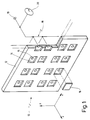
- FIG. 1 designates overall a workpiece carrier system as can be used within a handling system of a plastic injection molding machine known per se.
- Plastic injection molding machines of the type of interest here are generally known and therefore do not need to be explained in more detail.
- the workpiece carrier system 10 has a carrier plate 12 which can be moved in a plurality of coordinate directions x, y and z by means of travel units (not shown).
- the carrier plate 12 has a plurality of recesses 14, which are each adapted to the shape of the workpieces to be produced.
- each recess 14 is connected at the rear to a channel 15.
- the channels 15 are connected to a line system 18.
- the line system 18 leads overall to a vacuum connection 19.
- the pressure in the line system 18 can be monitored by means of a vacuum control display 20.
- the workpieces 16 can be held in the line system 18 by applying a negative pressure. If, however, one or more of the recesses 14 is not equipped with a workpiece 16 as a result of a fault, the build-up of the negative pressure in the line system 18 is hindered because the associated channel 15 connects the line system 18 to the ambient pressure in the relevant recess 14.
- the vacuum control display 20 will detect a fault in this case because a sufficiently large negative pressure cannot develop in the line system 18. For this purpose, the vacuum control display 20 is connected to an alarm system, not shown.
- FIG. 2 shows a top view of two extremely schematic tool halves 30a, 30b, which are each provided with mold cavities 32a, 32b.
- the tool halves 30a, 30b are in the open state.
- the mold cavity 32a, 32b was previously injected with plastic.
- the arrangement is such that the workpiece 16 is in the mold cavity 32a of the tool half 30a.
- all of this is only to be understood as an example.
- a handling system with a workpiece carrier system 10 according to FIG. 1 now moves laterally into the space between the tool halves 30a, 30b.
- the tool halves 30a, 30b are spaced apart by a relatively large opening stroke Z 1 , which can be reduced to Z 2 in the later automatic operation of the machine.
- the movement starts from a first position 40 at a lateral distance from the tool halves 30a, 30b.
- the workpiece carrier system 10 now moves in the direction -x between the tool halves 30a, 30b until a second position 41 is reached. From there, the workpiece carrier system 10 travels in the z direction to a third position 42. In the third position 42, the workpiece 16 is taken over.
- the workpiece 16 is either gripped by the tool carrier system 10 or ejected from the corresponding tool half 30a by means of ejectors, as indicated by an arrow 34 in FIG. 2.
- Fig. 3 shows that the workpiece carrier system 10 first moves in the direction -z to a fourth position 43 and then in the x-direction from the tool halves 30a, 30b to a fifth position 44 (optional) and finally to a sixth Position 45, which corresponds to the first position 40.
- the special feature of the method according to the invention is that this sequence of movements is also used when starting up the plastic injection molding machine, specifically from the first test cycle, which initially only serves to test the functioning of the injection molding process in the machine.
- the sequence of movements is modified in terms of time, as will now be explained with reference to FIGS. 4 to 6:
- a time interval ⁇ 1 t is now provided for the demolding or the transfer of the workpiece 16 from t 3 to t 4 .
- the time interval ⁇ 1 t depends on the respective transfer or demolding mechanism and can be almost zero in extreme cases.
- a second time interval ⁇ 2 t then follows the time t 5 , during which the workpiece carrier system 10 remains in the fourth position 43.
- the machine setter can now view and check the workpieces 16 accommodated in the workpiece carrier system 10, both with regard to their nature and with regard to their completeness. 1 that this check can be carried out relatively quickly because the workpieces 16 are in an orderly manner on the carrier plate 12 of the workpiece carrier system 10, for example in the Cartesian arrangement shown.
- the workpiece carrier system 10 is extended again from the time t 6 , specifically from the fourth position 43 in the x direction to the outside.
- the workpiece carrier system 10 can be briefly stopped again in a fifth position 44, namely an intermediate position at time t 7 , for a time interval ⁇ 3 t, in order to carry out a further check if necessary.
- This further check can take place, for example, by means of sensors which, for reasons of space, can only be used outside the tool halves 30a, 30b.
- the vacuum applied in the line system 18 can also be checked, for example, in the intermediate position 44.
- the speeds in the x direction are each designated v x1 and the speeds in the z direction are each designated v z1 .
- the speed profiles shown are to be understood only as examples and that, of course, non-linear profiles or profiles which are varied in some other way can also be used, as long as only the pause shown in the form of the time interval ⁇ 2 t is observed.
- the working speed ie the speed of movement of the workpiece carrier system 10 in the x and z directions
- the working speed can initially be increased according to FIG. 5. This is indicated in FIG. 5 by increased speeds v x2 and v z2 .
- the time profile is otherwise unchanged insofar as the required time intervals ⁇ 1 t, ⁇ 2 t have remained unchanged on the time scale.
- the total cycle time from t 1 to now t 9 * has been shortened because the travel times in the x and z directions have been shortened.
- the installer determines in one or more cycles that there are no faults, he can switch to automatic mode. This is shown in FIG. 6.
- the machine can initially be operated according to FIG. 6 at speeds v x2 , v z2 , which are still significantly below the maximum possible working speeds. Only when it has been determined after a certain number of N cycles (cf. DE 42 19 687 C2) that no malfunction occurs can a switch to an even higher working speed be made.
Landscapes
- Engineering & Computer Science (AREA)
- Manufacturing & Machinery (AREA)
- Mechanical Engineering (AREA)
- Robotics (AREA)
- Injection Moulding Of Plastics Or The Like (AREA)
- Moulds For Moulding Plastics Or The Like (AREA)
- Heating, Cooling, Or Curing Plastics Or The Like In General (AREA)
- Manufacture Of Motors, Generators (AREA)
Applications Claiming Priority (2)
| Application Number | Priority Date | Filing Date | Title |
|---|---|---|---|
| DE19601280 | 1996-01-16 | ||
| DE19601280A DE19601280C2 (de) | 1996-01-16 | 1996-01-16 | Verfahren zum Spritzgießen von Werkstücken |
Publications (3)
| Publication Number | Publication Date |
|---|---|
| EP0785060A2 true EP0785060A2 (fr) | 1997-07-23 |
| EP0785060A3 EP0785060A3 (fr) | 2000-02-02 |
| EP0785060B1 EP0785060B1 (fr) | 2003-10-01 |
Family
ID=7782828
Family Applications (1)
| Application Number | Title | Priority Date | Filing Date |
|---|---|---|---|
| EP97100085A Expired - Lifetime EP0785060B1 (fr) | 1996-01-16 | 1997-01-04 | Procédé de moulage par injection |
Country Status (5)
| Country | Link |
|---|---|
| US (1) | US5840222A (fr) |
| EP (1) | EP0785060B1 (fr) |
| JP (1) | JPH106374A (fr) |
| AT (1) | ATE251020T1 (fr) |
| DE (2) | DE19601280C2 (fr) |
Cited By (1)
| Publication number | Priority date | Publication date | Assignee | Title |
|---|---|---|---|---|
| US7481641B2 (en) | 2006-01-23 | 2009-01-27 | Infineon Technologies, Ag | Apparatus and method for producing an article by means of a molding technique |
Families Citing this family (5)
| Publication number | Priority date | Publication date | Assignee | Title |
|---|---|---|---|---|
| DE10211138A1 (de) * | 2002-03-14 | 2003-09-25 | Bayerische Motoren Werke Ag | Verfahren zur Prüfung spritzgegossener Kunststoffbauteile |
| US7214286B2 (en) * | 2004-01-30 | 2007-05-08 | Jarden Corporation | Stacked family molding and subsequent assembly process |
| JP6352852B2 (ja) * | 2015-04-27 | 2018-07-04 | ファナック株式会社 | 射出成形システム |
| JP6502994B2 (ja) * | 2017-04-07 | 2019-04-17 | ファナック株式会社 | 射出成形システムおよび射出成形方法 |
| IT201700074057A1 (it) * | 2017-07-03 | 2019-01-03 | Gd Spa | Metodo e macchina confezionatrice per la produzione di capsule per articoli da fumo, in particolare per filtri, realizzate per contenere un liquido da impiegare nel raffreddamento dei fumi |
Citations (1)
| Publication number | Priority date | Publication date | Assignee | Title |
|---|---|---|---|---|
| DE4219687C2 (de) | 1992-06-16 | 1994-05-05 | Richard Herbst | Verfahren zum Betrieb einer Spritzgießmaschine mit Werkzeugsicherung |
Family Cites Families (5)
| Publication number | Priority date | Publication date | Assignee | Title |
|---|---|---|---|---|
| DE1301014B (de) * | 1968-03-06 | 1969-08-14 | Eckert & Ziegler Gmbh | Verfahren und Vorrichtung zum Betrieb von Spritzgiessmaschinen |
| US4841364A (en) * | 1988-04-15 | 1989-06-20 | Kawaguchi, Ltd. | System for confirming the release of a molded article in an injection molding apparatus and for determining the quality of the article |
| DE4003372C1 (fr) * | 1990-02-05 | 1991-07-18 | Richard 8057 Eching De Herbst | |
| JPH06195765A (ja) * | 1992-12-25 | 1994-07-15 | Ricoh Co Ltd | 光ディスク基板用成形品取出し方法及び装置 |
| JPH07237256A (ja) * | 1994-02-28 | 1995-09-12 | Omron Corp | 不良改善用の調整項目抽出方法およびその方法を用いた条件調整用の知識データ生成方法並びに不良改善用の調整項目抽出装置およびその装置を用いた条件調整用の知識データ生成システム |
-
1996
- 1996-01-16 DE DE19601280A patent/DE19601280C2/de not_active Expired - Fee Related
-
1997
- 1997-01-04 EP EP97100085A patent/EP0785060B1/fr not_active Expired - Lifetime
- 1997-01-04 AT AT97100085T patent/ATE251020T1/de not_active IP Right Cessation
- 1997-01-04 DE DE59710794T patent/DE59710794D1/de not_active Expired - Fee Related
- 1997-01-10 JP JP9013166A patent/JPH106374A/ja active Pending
- 1997-01-16 US US08/786,381 patent/US5840222A/en not_active Expired - Fee Related
Patent Citations (1)
| Publication number | Priority date | Publication date | Assignee | Title |
|---|---|---|---|---|
| DE4219687C2 (de) | 1992-06-16 | 1994-05-05 | Richard Herbst | Verfahren zum Betrieb einer Spritzgießmaschine mit Werkzeugsicherung |
Cited By (1)
| Publication number | Priority date | Publication date | Assignee | Title |
|---|---|---|---|---|
| US7481641B2 (en) | 2006-01-23 | 2009-01-27 | Infineon Technologies, Ag | Apparatus and method for producing an article by means of a molding technique |
Also Published As
| Publication number | Publication date |
|---|---|
| US5840222A (en) | 1998-11-24 |
| DE19601280C2 (de) | 1998-12-17 |
| EP0785060A3 (fr) | 2000-02-02 |
| ATE251020T1 (de) | 2003-10-15 |
| DE59710794D1 (de) | 2003-11-06 |
| JPH106374A (ja) | 1998-01-13 |
| EP0785060B1 (fr) | 2003-10-01 |
| DE19601280A1 (de) | 1997-07-17 |
Similar Documents
| Publication | Publication Date | Title |
|---|---|---|
| AT519508B1 (de) | Regelvorrichtung für ein Handlinggerät | |
| DE4003371C2 (fr) | ||
| DE4003372C1 (fr) | ||
| DE19601280C2 (de) | Verfahren zum Spritzgießen von Werkstücken | |
| EP2560802B1 (fr) | Procédé pour retirer des articles moulés par injection et appareil correspondant | |
| DE102005061193B4 (de) | Handhabungsverfahren und -vorrichtung, insbesondere an einer Spritzgussmaschine | |
| EP3804943A1 (fr) | Moitié d'outil et procédé de fabrication d'une pièce moulée par injection pourvue d'au moins une pièce d'insertion | |
| DE19716777C2 (de) | Verfahren zum Betreiben eines Handhabungsgerätes an einer Kunststoffverarbeitungsmaschine | |
| DE3936555A1 (de) | Handhabungsautomat | |
| DE102016119840A1 (de) | Formschließeinheit mit einer Formhöhenverstellung sowie Verfahren zu deren Betätigung | |
| EP3804944B1 (fr) | Moitié d'outil et procédé de fabrication d'une pièce moulée par injection pourvu d'au moins une pièce d'insertion en forme de douille | |
| EP2886283A1 (fr) | Dispositif de fabrication de pièces en matière plastique ayant des inserts dans un procédé de moulage par injection | |
| EP3253549B1 (fr) | Appareil de moulage pour fabriquer des pièces en matière plastique | |
| DE102007000994A1 (de) | Spritzgießvorrichtung zur Herstellung von Kunststoffbauteilen aus wenigstens zwei Kunststoffkomponenten | |
| EP1534474B1 (fr) | Dispositif de prelevement pour pieces moulees par injection et procede de prelevement automatique | |
| EP3717202B1 (fr) | Dispositif pour enlever des produits en plastique | |
| EP0108192A2 (fr) | Dispositif pour éliminer des pièces injectées et filetées en matière plastique de l'outil d'une machine à couler par injection | |
| WO2007099142A1 (fr) | Système pourvu d'un dispositif de vérification et / ou de maintenance pour l'extraction de d'ébauches | |
| EP3811821B1 (fr) | Procédé d'inspection d'un outil d'insertion d'un outil de bourrage d'une machine de fabrication de brosses et machine de fabrication de brosses | |
| DE19615122C1 (de) | Schließeinheit für eine Kunststoff-Spritzgießmachine | |
| DE102004027224A1 (de) | Thermoformmaschine und Verfahren zum Betreiben einer Thermoformmaschine | |
| EP3465365A1 (fr) | Installation de production pour la fabrication d'un grand nombre d'articles et procédé de commande et/ou de surveillance de l'installation de production | |
| EP4614259A1 (fr) | Procédé et système de chargement et/ou de déchargement automatiques d'une installation de traitement et/ou de fabrication automatisée au moyen d'une unité d'automatisation | |
| EP2029346B1 (fr) | Dispositif de positionnement | |
| DE10316527A1 (de) | Verfahren und Vorrichtung zum Steuern der Bewegungsabläufe zwischen einer Produktionsmaschine und einem Handlingsystem |
Legal Events
| Date | Code | Title | Description |
|---|---|---|---|
| PUAI | Public reference made under article 153(3) epc to a published international application that has entered the european phase |
Free format text: ORIGINAL CODE: 0009012 |
|
| AK | Designated contracting states |
Kind code of ref document: A2 Designated state(s): AT BE CH DE DK ES FR GB IT LI NL SE |
|
| PUAL | Search report despatched |
Free format text: ORIGINAL CODE: 0009013 |
|
| AK | Designated contracting states |
Kind code of ref document: A3 Designated state(s): AT BE CH DE DK ES FR GB IT LI NL SE |
|
| 17P | Request for examination filed |
Effective date: 20000707 |
|
| 17Q | First examination report despatched |
Effective date: 20010521 |
|
| RAP1 | Party data changed (applicant data changed or rights of an application transferred) |
Owner name: HEKUMA GMBH |
|
| RIN1 | Information on inventor provided before grant (corrected) |
Inventor name: HERBST, RICHARD |
|
| GRAH | Despatch of communication of intention to grant a patent |
Free format text: ORIGINAL CODE: EPIDOS IGRA |
|
| GRAS | Grant fee paid |
Free format text: ORIGINAL CODE: EPIDOSNIGR3 |
|
| GRAA | (expected) grant |
Free format text: ORIGINAL CODE: 0009210 |
|
| AK | Designated contracting states |
Kind code of ref document: B1 Designated state(s): AT BE CH DE DK ES FR GB IT LI NL SE |
|
| PG25 | Lapsed in a contracting state [announced via postgrant information from national office to epo] |
Ref country code: NL Free format text: LAPSE BECAUSE OF FAILURE TO SUBMIT A TRANSLATION OF THE DESCRIPTION OR TO PAY THE FEE WITHIN THE PRESCRIBED TIME-LIMIT Effective date: 20031001 Ref country code: FR Free format text: LAPSE BECAUSE OF FAILURE TO SUBMIT A TRANSLATION OF THE DESCRIPTION OR TO PAY THE FEE WITHIN THE PRESCRIBED TIME-LIMIT Effective date: 20031001 |
|
| REG | Reference to a national code |
Ref country code: GB Ref legal event code: FG4D Free format text: NOT ENGLISH |
|
| REG | Reference to a national code |
Ref country code: CH Ref legal event code: EP |
|
| REG | Reference to a national code |
Ref country code: CH Ref legal event code: NV Representative=s name: ROTTMANN, ZIMMERMANN + PARTNER AG |
|
| REF | Corresponds to: |
Ref document number: 59710794 Country of ref document: DE Date of ref document: 20031106 Kind code of ref document: P |
|
| GBT | Gb: translation of ep patent filed (gb section 77(6)(a)/1977) | ||
| PG25 | Lapsed in a contracting state [announced via postgrant information from national office to epo] |
Ref country code: SE Free format text: LAPSE BECAUSE OF FAILURE TO SUBMIT A TRANSLATION OF THE DESCRIPTION OR TO PAY THE FEE WITHIN THE PRESCRIBED TIME-LIMIT Effective date: 20040101 Ref country code: DK Free format text: LAPSE BECAUSE OF FAILURE TO SUBMIT A TRANSLATION OF THE DESCRIPTION OR TO PAY THE FEE WITHIN THE PRESCRIBED TIME-LIMIT Effective date: 20040101 |
|
| PG25 | Lapsed in a contracting state [announced via postgrant information from national office to epo] |
Ref country code: ES Free format text: LAPSE BECAUSE OF FAILURE TO SUBMIT A TRANSLATION OF THE DESCRIPTION OR TO PAY THE FEE WITHIN THE PRESCRIBED TIME-LIMIT Effective date: 20040112 |
|
| PGFP | Annual fee paid to national office [announced via postgrant information from national office to epo] |
Ref country code: GB Payment date: 20040128 Year of fee payment: 8 |
|
| PG25 | Lapsed in a contracting state [announced via postgrant information from national office to epo] |
Ref country code: BE Free format text: LAPSE BECAUSE OF NON-PAYMENT OF DUE FEES Effective date: 20040131 |
|
| NLV1 | Nl: lapsed or annulled due to failure to fulfill the requirements of art. 29p and 29m of the patents act | ||
| BERE | Be: lapsed |
Owner name: *HEKUMA G.M.B.H. Effective date: 20040131 |
|
| PLBE | No opposition filed within time limit |
Free format text: ORIGINAL CODE: 0009261 |
|
| STAA | Information on the status of an ep patent application or granted ep patent |
Free format text: STATUS: NO OPPOSITION FILED WITHIN TIME LIMIT |
|
| 26N | No opposition filed |
Effective date: 20040702 |
|
| EN | Fr: translation not filed | ||
| PG25 | Lapsed in a contracting state [announced via postgrant information from national office to epo] |
Ref country code: IT Free format text: LAPSE BECAUSE OF NON-PAYMENT OF DUE FEES;WARNING: LAPSES OF ITALIAN PATENTS WITH EFFECTIVE DATE BEFORE 2007 MAY HAVE OCCURRED AT ANY TIME BEFORE 2007. THE CORRECT EFFECTIVE DATE MAY BE DIFFERENT FROM THE ONE RECORDED. Effective date: 20050104 Ref country code: GB Free format text: LAPSE BECAUSE OF NON-PAYMENT OF DUE FEES Effective date: 20050104 |
|
| GBPC | Gb: european patent ceased through non-payment of renewal fee |
Effective date: 20050104 |
|
| PGFP | Annual fee paid to national office [announced via postgrant information from national office to epo] |
Ref country code: AT Payment date: 20060123 Year of fee payment: 10 |
|
| PGFP | Annual fee paid to national office [announced via postgrant information from national office to epo] |
Ref country code: CH Payment date: 20060124 Year of fee payment: 10 |
|
| PGFP | Annual fee paid to national office [announced via postgrant information from national office to epo] |
Ref country code: DE Payment date: 20060328 Year of fee payment: 10 |
|
| PG25 | Lapsed in a contracting state [announced via postgrant information from national office to epo] |
Ref country code: LI Free format text: LAPSE BECAUSE OF NON-PAYMENT OF DUE FEES Effective date: 20070131 Ref country code: CH Free format text: LAPSE BECAUSE OF NON-PAYMENT OF DUE FEES Effective date: 20070131 |
|
| PG25 | Lapsed in a contracting state [announced via postgrant information from national office to epo] |
Ref country code: DE Free format text: LAPSE BECAUSE OF NON-PAYMENT OF DUE FEES Effective date: 20070801 |
|
| REG | Reference to a national code |
Ref country code: CH Ref legal event code: PL |
|
| PG25 | Lapsed in a contracting state [announced via postgrant information from national office to epo] |
Ref country code: AT Free format text: LAPSE BECAUSE OF NON-PAYMENT OF DUE FEES Effective date: 20070104 |