EP0785157B1 - Verfahren und Vorrichtung zum Aufwickeln - Google Patents
Verfahren und Vorrichtung zum Aufwickeln Download PDFInfo
- Publication number
- EP0785157B1 EP0785157B1 EP97100476A EP97100476A EP0785157B1 EP 0785157 B1 EP0785157 B1 EP 0785157B1 EP 97100476 A EP97100476 A EP 97100476A EP 97100476 A EP97100476 A EP 97100476A EP 0785157 B1 EP0785157 B1 EP 0785157B1
- Authority
- EP
- European Patent Office
- Prior art keywords
- web
- mandrel
- articulatable
- mandrels
- winding
- Prior art date
- Legal status (The legal status is an assumption and is not a legal conclusion. Google has not performed a legal analysis and makes no representation as to the accuracy of the status listed.)
- Expired - Lifetime
Links
- 238000004804 winding Methods 0.000 title claims description 45
- 238000000034 method Methods 0.000 title claims description 25
- 239000000463 material Substances 0.000 claims description 13
- 238000011144 upstream manufacturing Methods 0.000 claims description 10
- 230000007246 mechanism Effects 0.000 claims description 5
- 125000004122 cyclic group Chemical group 0.000 claims description 3
- 230000008859 change Effects 0.000 description 7
- 239000003292 glue Substances 0.000 description 7
- 230000008901 benefit Effects 0.000 description 4
- 238000010276 construction Methods 0.000 description 3
- 230000008569 process Effects 0.000 description 3
- 238000004519 manufacturing process Methods 0.000 description 2
- 239000004677 Nylon Substances 0.000 description 1
- 229920002472 Starch Polymers 0.000 description 1
- 239000004809 Teflon Substances 0.000 description 1
- 229920006362 Teflon® Polymers 0.000 description 1
- 230000009471 action Effects 0.000 description 1
- 239000000853 adhesive Substances 0.000 description 1
- 230000001070 adhesive effect Effects 0.000 description 1
- 239000003795 chemical substances by application Substances 0.000 description 1
- 230000003247 decreasing effect Effects 0.000 description 1
- 230000009977 dual effect Effects 0.000 description 1
- 239000004744 fabric Substances 0.000 description 1
- 229920001821 foam rubber Polymers 0.000 description 1
- 239000002783 friction material Substances 0.000 description 1
- 230000003100 immobilizing effect Effects 0.000 description 1
- 239000012939 laminating adhesive Substances 0.000 description 1
- 229920001778 nylon Polymers 0.000 description 1
- 238000003825 pressing Methods 0.000 description 1
- 125000006850 spacer group Chemical group 0.000 description 1
- 239000007921 spray Substances 0.000 description 1
- 235000019698 starch Nutrition 0.000 description 1
- 239000008107 starch Substances 0.000 description 1
- 230000037303 wrinkles Effects 0.000 description 1
Images


Classifications
-
- B—PERFORMING OPERATIONS; TRANSPORTING
- B65—CONVEYING; PACKING; STORING; HANDLING THIN OR FILAMENTARY MATERIAL
- B65H—HANDLING THIN OR FILAMENTARY MATERIAL, e.g. SHEETS, WEBS, CABLES
- B65H19/00—Changing the web roll
- B65H19/22—Changing the web roll in winding mechanisms or in connection with winding operations
- B65H19/28—Attaching the leading end of the web to the replacement web-roll core or spindle
-
- B—PERFORMING OPERATIONS; TRANSPORTING
- B65—CONVEYING; PACKING; STORING; HANDLING THIN OR FILAMENTARY MATERIAL
- B65H—HANDLING THIN OR FILAMENTARY MATERIAL, e.g. SHEETS, WEBS, CABLES
- B65H19/00—Changing the web roll
- B65H19/22—Changing the web roll in winding mechanisms or in connection with winding operations
- B65H19/2207—Changing the web roll in winding mechanisms or in connection with winding operations the web roll being driven by a winding mechanism of the centre or core drive type
- B65H19/2223—Turret-type with more than two roll supports
-
- B—PERFORMING OPERATIONS; TRANSPORTING
- B65—CONVEYING; PACKING; STORING; HANDLING THIN OR FILAMENTARY MATERIAL
- B65H—HANDLING THIN OR FILAMENTARY MATERIAL, e.g. SHEETS, WEBS, CABLES
- B65H2301/00—Handling processes for sheets or webs
- B65H2301/40—Type of handling process
- B65H2301/41—Winding, unwinding
- B65H2301/414—Winding
- B65H2301/41419—Starting winding process
- B65H2301/41426—Starting winding process involving suction means, e.g. core with vacuum supply
-
- B—PERFORMING OPERATIONS; TRANSPORTING
- B65—CONVEYING; PACKING; STORING; HANDLING THIN OR FILAMENTARY MATERIAL
- B65H—HANDLING THIN OR FILAMENTARY MATERIAL, e.g. SHEETS, WEBS, CABLES
- B65H2406/00—Means using fluid
- B65H2406/30—Suction means
-
- B—PERFORMING OPERATIONS; TRANSPORTING
- B65—CONVEYING; PACKING; STORING; HANDLING THIN OR FILAMENTARY MATERIAL
- B65H—HANDLING THIN OR FILAMENTARY MATERIAL, e.g. SHEETS, WEBS, CABLES
- B65H2408/00—Specific machines
- B65H2408/20—Specific machines for handling web(s)
- B65H2408/23—Winding machines
- B65H2408/231—Turret winders
- B65H2408/2315—Turret winders specified by number of arms
- B65H2408/23157—Turret winders specified by number of arms with more than three arms
Definitions
- This invention relates to a method and apparatus for convolute winding and, more particularly, to the winding into logs or rolls of webs such as bathroom tissue and kitchen toweling.
- the invention is concerned with winding on a mandrel such as is commonly used in center-type winding.
- a mandrel such as is commonly used in center-type winding.
- center-type winding the input speed to the roll being developed is gradually reduced as the diameter increases. This is in contrast to surface winding where the input speed is constant throughout the wind.
- center-type winding was the type described in co-owned patents US-A-2,512,900 and US-A-2,769,600.
- This type of rewinder was superseded by the rewinder shown and described in co-owned patent US Re. 28,353 which was not subject to the 1,000 feet per minute (about 300 meters per minute) web speed limitation and is still the state of the art for center-type winders.
- a detailed explanation of these winders can be found in the United States court opinion reported at 680 F2d 483.
- a key feature of the reissue patent was the bedroll and cutoff roll.
- the invention here provides a simple mechanism which cuts off the web material and transfers it to a new mandrel or core in one motion. It eliminates the costly bedroll and cutoff roll commonly used to transfer the web in center winders. Further, previous mandrel winders equipped with a bedroll were limited to sheet counts on the finished consumer roll to multiples of the bedroll diameter, most commonly, the bedroll circumference was ten sheets of tissue or five sheets of towel.
- the invention herein provides single sheet count capability with variable length perforation and it also limits transfer glue to the first revolution of the wind, features previously only available in surface winders.
- the invention further provides the ability to wind either cored product or coreless product - the latter by equipping the winding mandrels with vacuum as disclosed in US-A-5,660,349 corresponding to EP-A-695 713.
- the invention which is defined in claims 1 and 15 below makes use of an indexable rotatable arm means which rotates through 360° about an axis outside of the orbital path of the mandrels.
- the articulatable part of the arm means is constructed to rotate meanwhile so that the resultant speed of the part is the same or faster than web speed in the web direction to sever the web and start winding the web in conjunction with a clamping action on the "new" mandrel, i.e., the mandrel next in line behind the mandrel on which the web is then being wound.
- the inventive rewinder has a frame generally designated 30 (see FIG. 2) and consisting of side frames 30a and 30b (see FIG. 1). This supports a multi-station turret generally designated 31 for rotation about axis 31a.
- the entering web is designated W and is normally derived from a parent roll (not shown) of substantial width, viz., 90" (2.3 meters) on up.
- the web is advanced toward a path W' by draw rollers 32, 33 and through a perforator generally designated 34.
- the perforator may be omitted and a log or roll produced which has no transverse perforations.
- the perforator 34 includes a blade roller 35 and a knife bar 36.
- Illustrative of a widely used perforator is that of co-owned Patent US-A-2,870,840.
- FIGS. 1 and 2 a direction changing means -- illustrated in FIGS. 1 and 2 as a stationary idler roller 37.
- This is eminently suitable for operations with cores but different direction changing means are required for coreless operation -- to be described hereinafter with respect to FIGS. 20-26 where there is an enveloping roller 138 as indicated at the left of FIG. 20.
- the turret 31 has four mandrels 39, 40, 41 and 42. It will be appreciated that a greater or lesser number of mandrels (or stations) may be employed, with the minimum number being two. Such turret constructions are well known -- see coowned Patent US-A-2,769,600.
- the turret 31 is generally spider-like, being equipped with arms (as at 42a relative to the mandrel 42 in FIG. 2) for carrying the various mandrels.
- the mandrel 42 has a completely wound log L mounted thereon and the mandrel is in position for stripping the log therefrom by a stripping conveyor 43.
- the frame 30 is equipped with a core loader 44 which functions to ensleeve a core on a mandrel in the 41 position -- here about 8 o'clock.
- the numeral 45 designates generally the previously mentioned articulatable arm means which cooperates with the mandrels in sequence to provide a novel rewinding operation.
- the turret 31 is equipped with four mandrels starting at 39 where a log L' is in the process of being wound. Then, proceeding counterclockwise, the next mandrel to be wound is .designated 40, a still subsequent mandrel to designated 41 and which is in the process of being ensleeved by a core while lastly a still further mandrel is designated 42 and from which the finished log L is being stripped.
- the arm means 45 includes an articulatable part 46 which functions as a wiper or wiping means and can be a pad, brush, wiper, etc. and which is rotatably mounted on the main arm 47.
- the articulatable part or wiping means 46 continues to rotate at a selected speed, viz., at or above web speed.
- the turret 31 is in its dwell position, i.e., not indexing, and the main arm 47 is also not rotating.
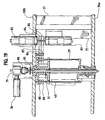
- FIG. 3 showing is of the arm means 45 at about 12:30 o'clock.
- the arm means 45 rotates counterclockwise about an axis 48 as indicated by the direction arrow 48a.
- the mandrel 40 has been indexed almost into contact with the web W.
- the mandrel 40 is ensleeved with a new core and adhesive sprayed onto the core. This is done by spray guns 29 just before transfer (see FIG. 2). But, by the time the mandrel 40 reaches its FIG. 3 position, it has been accelerated up to web speed.
- This view shows the arm means 45 in a more advanced position, i.e., further counterclockwise -- say at about 8 o'clock as contrasted to the 12:30 o'clock position in FIG. 3.
- the arm means 45 is now at full rotational velocity while the wiping means 46 has been rotating continuously at its selected speed. As seen in FIG. 4, the wiping means 46 is approximately one-quarter revolution of its rotation away from contact with the web W and the start of transfer.
- FIG. 5 shows the wiping means 46 as it makes contact with the web W.
- the leading edge of the wiping means makes contact near the perforation where cut-off is desired.
- Various web conditions and speeds determine precisely where the contact point should be made.
- the edge of the wiping means is made sharp, or equipped with teeth to cut the web material as it strikes into it.
- the resultant speed of the wiping means 46 can be varied depending upon web characteristics. On low stretch webs, a speed of 10-20% faster than web speed works well, on higher stretch webs, the speed may go up to 50% faster than web speed or more. For most tissue and towel papers, between 20 and 50% faster than web speed works well. At the minimum, the selected speed of the wiping means 46 should be the same as the predetermined web speed. It will be appreciated that the surface speed of the wiping means 46 is the resultant of the combined rotations of the main arm 47 and the means 46 inasmuch as both are rotating counterclockwise. The main arm, in a typical production will rotate at 100 rpm while the web speed is of the order of 3000 fpm (900 mpm) and the wiping means typically would be 3600-4000 fpm (1100-1200 mpm).
- the wiping means 46 makes contact with the web (which is supported by the core-equipped mandrel), it quickly depresses the web onto the glued core on the mandrel 40.
- the sticky glue on the core holds the sheet at web speed while the wiping means 46 moves forward at a faster speed.
- the leading edge of the wiping means pulls the web forward, ahead of the line of perforation, while the glue holds the other side of the perforation with the glue at web speed -- the core surface speed being web speed at transfer.
- the web material is elongated at the perforation, and breaks at the line of perforation.
- the invention isolates the tension required to break the web to a very small part of the web. This is desirable to protect the embossments and web bulk added to many web materials.
- the geometry of the wiping means 46 and mandrel 40 provides an additional tension in the web about a line of transverse perforation -- or even a line of potential severance, as where no perforation has been provided. This can be appreciated from the distortion of the web W at the point W 0 in FIG. 14.
- FIG. 10 Comparing FIG. 10 with FIG. 6 reveals that there has been relatively little rotation of the main arm 47 (the arm in both showings being at about the 8 o'clock position) but where there has been considerable rotation of the wiping means 46.
- the wiping means is at almost a 9 o'clock position but by the time FIG. 10 has been reached, the counterclockwise rotation of the wiping means 46 brings its contacting edge to about a 5:30 o'clock position.
- FIG. 11 shows the arm means 45 nearing the end of its index and coming to a stop -- compare with FIG. 2.
- the newly transferred web is now winding on the new mandrel 40 as the finished wound log L begins to decelerate to a stop for ultimate removal from the mandrel 39.
- FIG. 12 shows the turret 31 beginning to index so that the finished wound log L can be removed, a new core loaded and a freshly loaded core glued and accelerated to speed for the next transfer.
- the arm 47 has reached its dwell state -- compare the showings of FIGS. 11, 12 and 2. But the wiping means keeps rotating as can be appreciated from a comparison of FIGS. 10 and 11.
- the wiping means 46 is ahead of the arm 47 while in FIG. 11 it is behind the arm 47.
- FIG. 10 This view shows how the wiping means comes into contact with the web just slightly downstream of the line of perforation P.
- downstream is used in the context of the web travel direction -- starting in the frame 30 at the upstream end with the spreader roller 30c (see the right hand ends of FIGS. 2 and 17).
- the wiping means 46 rotates about an axis of rotation 49 which is carried at the free end of the arm 47 -- see FIG. 10.
- the other, or fixed end, of arm 47 is mounted for rotation about the axis 48 -- see FIG. 9.
- This axis 48 is clearly outside the orbital path of the mandrels -- designated 51 in FIG. 9.
- the wiping means 46 does protrude into the inside of the orbit as can be appreciated from the curved dashed-line path 52 in FIG. 11.
- wiping means 46 in the embodiment illustrated has a curved surface for contacting a mandrel and is covered by a thin, curved pad 53 advantageously constructed of velcro, closed cell foam rubber or other resilient deformable material.
- a nylon brush can be used to advantage by using a pad or wiper no more less than about 6.4 mm (1 ⁇ 4") in thickness -- from which two benefits are realized.
- the relative thinness permits the more rigid backing material of the supporting elements 54 making up the wiping means 46 to exert a pressure against the web and core, thereby achieving a secure glue bond.
- the elements 54 are spaced along the width of the rewinder -- as can be seen in the central part of FIG. 18. In FIGS. 13-16, it is seen that the elements 54 have notches or cut-outs as at 54a in FIG. 16 to lighten the loading.
- FIG. 15 is just slightly after that of FIG. 14 and it will be seen that the tail T now is definitely separated from the leading edge E of the now-severed web W.
- the mandrel 40 has rotated about 90° from its FIG. 13 position.
- the wiping means 46 may be advantageous to equip the wiping means 46 with a strip of friction material as at 56 to facilitate the grip of the corner 55 of the wiping means 46 on the web W.
- Emery cloth, fine sandpaper or a variety of friction surface materials can be used to advantage for this purpose and it is only necessary to have a strip of a width up to about 25.4 mm (1") in width -- in the direction of web travel.
- the strip advantageously extends across the width of the rewinder which, as indicated previously, normally operates on webs having transverse dimensions of 90" (2.3 meters) and up.
- FIG. 17 the numeral 30c at the extreme right in FIG. 17 designates a spreader roller also seen in the extreme right upper portion of FIG. 2.
- the web W encounters the draw rollers 32, 33 and also in FIG. 17 at the right center.
- the web encounters the perforator 34 (see FIG. 2) which is made up of a blade roller 35 and a knife bar 36.
- the extreme left showing of FIG. 17 reveals the presence of the web direction changing means in the form of idler roller 37.
- a spreader roller 30c which removes wrinkles before the web W is advanced toward the path W' by draw rollers 32, 33.
- the roller 32 is fixed while the roller 33 is pivotably mounted.
- the numeral 57 designates the two pivot arms and the numeral 58 designates the loading cylinders for the draw roller 33.
- the draw rollers are driven -- from the perforator roll 35. So, before going in to the drive, we first discuss the perforator in connection with FIG. 17.
- the first operation performed on the web normally is cross perforation as by the perforator 34 which as previously described includes at least one rotating blade roller 35 operated by a drive pulley 59 or a servo motor similar to 82 in FIG. 19 if variable perforation length is desired.
- the engagement of the web with the perforator 34 results in providing the web with equally longitudinally spaced lines of transverse perforation.
- the knife bar 36 is equipped with lift cylinders 60.
- the drive pulley 59 is coupled by a cog belt 61 (see the lower left portion of FIG. 17) to the rewinder main drive input pulley 62.
- a cog belt 61 see the lower left portion of FIG. 17
- one end of the perforator roller shaft 63 is equipped with pulley 59 while the other end has a pulley 64.
- This pulley 64 is connected via belt 65 to a variable speed drive 66 which, in turn, is connected to the shaft 67 of the fixed draw roll 32.
- a timing belt drive 68 connects the draw roll 32 with the draw roll 33.
- Last in proceeding to the left in FIG. 17 is the idler roller 37.
- FIG. 18 For the next level of structure, please refer to FIG. 18.
- each bracket 69 carries a stationary stub 70 to provide an axis 48 for the main arm 47 in the form of a stub shaft 71.
- a servo motor 72 is coupled to the stub shaft 71.
- a suitable belt drive 73 connects the output of the servo motor 72 to the shaft 71 so as to rotate the arm means 45.
- a similar servo motor 74 is provided on the opposite frame 30a for rotating the articulatable part or wiping means 46. As seen in FIG. 18, there is a drive connection from the output of the servo motor 74 to the shaft 76 which carries the wiping means 46.
- the lowest level in FIG. 2 contains the turret, mandrels and drives. Again, the frames are designated 30a and 30b and these are also seen in FIG. 19.
- FIG. 19 Especially seen in FIG. 19 is the turret 31 and the mandrels 39, 40.
- the turret 31 is rotatably mounted in the side frames 30a, 30b. These side frames are interconnected by spacers as at 77 -- see the right side of FIG. 19.
- the output of the turret drive motor 78 is delivered to a right angle gear box 79 and a clutch 80.
- the output of clutch 80 is a shaft 81 which is keyed or otherwise fixed to the spider-like turret 31.
- a pair of motors 82, 83 are provided for driving the mandrels.
- the motor 82 drives the even numbered mandrels, viz., 40 and 42 of FIG. 2 while the motor 83 drives the odd numbered mandrels 39, 41.
- Each motor output shaft is connected to a drive as at 84, 85 that is entrained over idlers 86, 87 and then over mandrel pulleys 88, 89.
- one pulley 88, 89 is keyed to a first mandrel while the other 89, 88 is rotatably mounted on the second mandrel in question.
- Each mandrel advantageously is of the core lock type as seen in co-owned Patent US-A-4,635,871.
- the first is to provide vacuum type mandrels (of the type depicted in co-owned European application 616965) and the second is to provide an enveloping roller as at 138 in FIGS. 18A and 20.
- the enveloping roller 138 as seen in FIGS. 21-24.
- the numerals for elements similar to those of the "core" embodiment are the same but increased by 100.
- the turret is 131 and the mandrels starting from the one being wound are, respectively, 139, 140, 141 and 142.
- the web W passes around an idler roller -- here designated 137.
- the web then passes around the enveloping roller 138 which, in this embodiment, also performs a direction changing function for the web.
- the function of the roller 138 is described in greater detail in the above-identified application EP-A-695713 where it is also described as an enveloping roller.
- the roller 138 pivots in a counterclockwise fashion as can be appreciated from the sequence of views FIGS. 21-24 so as to cause the web W to wrap the mandrel 140.
- the articulatable arm means 145 bears against the web to anchor the web to itself.
- the roller 138 in its enveloping mode is used advantageously for coreless product where the web is attached to the mandrel with vacuum and the enveloping assists the vacuum to hold the web.
- the roller 138 may either be omitted or remain stationary and out of the web path.
- the rewinder includes a frame 130, perforator roller 135, knife bar 136 following draw rollers 132 and 133. Featured prominently is the enveloping roller 138 and a box 190 housing the controls, compressor, etc. to provide vacuum in the mandrels.
- FIG. 21 Showing
- the first mandrel 139 is the mandrel being wound with the web W.
- the next mandrel 140 is seen approaching a position of contact with the web W as the turret 121 rotates clockwise.
- the mandrel 140 is now being accelerated to web speed.
- the enveloping roller 138 has been pivoted to a substantial distance away from the mandrel 140.
- FIG. 22 Showing
- the enveloping roller 138 has started to pivot counterclockwise (see arrow 191) from its position in FIG. 21 to become partially enveloped by the web and also develop a partial enveloping relation of the web with the mandrel 140.
- the web W is still being wound on mandrel 139.
- the actuatable arm means 145 starts to move toward the mandrel 140. This has been omitted from FIG. 22 but its position and orientation would be that of the arm means 45 between FIGS. 3 and 4 -- as do the showings in FIGS. 23 and 24.
- FIG. 23 showing
- mandrel 140 is seen to be further wrapped by the web W because the enveloping roller 138 has moved further counterclockwise from its position in FIG. 22 -- see the arrow 192.
- FIG. 24 Showing
- FIG. 24 The situation at cutoff and transfer is illustrated in FIG. 24 where a log L is almost completely wound on the mandrel 139.
- the mandrel 140 is now backed by the enveloping roller 138.
- the enveloping roller 138 has pivoted to its furthest counterclockwise position along the path designated by the arrow 193 and mandrel 140 is ready for engagement by the arm means 145 -- as in FIG. 6.
- the operational sequence for coreless production is thereafter the same as with cores, viz., like FIGS. 7-12.
- the only roller in FIG. 18A is the enveloping roller 138 which is pivotally, rotatably mounted on the side frames 30a, 30b.
- Two servo motors are provided for this dual movement.
- a servo motor 194 controls the pivotal position of the enveloping roller 138 while servo motor 195 controls the rotational speed of the enveloping roller 138.
- a pair of pivot arms 196 are journaled at one end on members 197, 198. Adjacent their other ends, the arms 196 rotatably carry the shaft 199 of the enveloping roller 138. At the ends near the connection of the shaft 199, the arms 196 are coupled to a pivot linkage 200 fixed to a transverse shaft 201 driven by the servo motor 194. This provides for pivoting the enveloping roller 138 from a first position (FIG. 21) where the web is out of contact with the enveloping roller 138 to a second position (FIG. 24) where the web W is wrapped about both the enveloping roller and the mandrel 140.
- the servo motor 195 is equipped with an output shaft 202 which extends through the member 197.
- the inner end of shaft 202 is coupled by a belt drive 203 to the shaft 199 of the enveloping roller 138.
- FIG. 25 This view illustrates a typical mandrel 140 which is equipped with vacuum passages to retain the web W against the mandrel periphery as it is being wrapped on the mandrel by the enveloping roller 138. Due to size limitations, the vacuum ports cannot be seen in FIG. 25 but can be seen at 205 in the larger scale version of FIG. 26. Where it is desirable in the final roll product to keep the central opening from collapsing, transfer agents such as starch or a laminating adhesive can be applied by the nozzle means 204 to a position spaced from the leading edge of the web, i.e., the line of perforation where severance is to occur. This results in ply bonding of the initially wound layers of web material.
- transfer agents such as starch or a laminating adhesive
- This view illustrates a fluted mandrel as at 140'.
- the fluted or spline version is advantageous where the mandrel diameter is so small as not to effectively accommodate adequate vacuum passages for machines of the order of 2.54 m (100") in width.
- mandrels of about a 1 to 1-1 ⁇ 2" (25-37 mm.) diameter can accommodate the vacuum passages and ports 205.
- the vacuum passages and ports 205 assist in effecting transfer, i.e., holding the severed web against the "new" mandrels.
- the fluted mandrels assist in transfer by immobilizing the web on the mandrel surface.
- the mandrels with smooth surfaces are advantageously teflon-coated.
- the mandrel vacuum is effective to keep the web material on the mandrel.
- the vacuum keeps the transfer uniform and reduces wrinkling of the web which can cause high tension points.
- the ports may have countersunk openings facing the web W so as to improve holding strength and permit a lower vacuum.
- a mandrel with both flutes and vacuum permits web speeds up to about 2500 feet per minute (762 meters per minute).
- the numeral 206 in FIG. 20 designates a controller which controls the operation of the various rollers and, especially the pivoting and rotation thereof, i.e., the various motors described in conjunction with FIGS. 17-19.
- the speed of the enveloping roller 138 along with the mandrel speed is controlled to compensate for the changing web length from the perforator to the log being wound when the enveloping roller 138 and turret 131 change position -- compare FIGS. 21 through 24.
- the mandrel 139 speeds up or slows down to correct for the change without changing tension. Some tension change could be permitted depending on the percent of stretch available in the web material. It is advantageous to change the enveloping roller rotational position (speed) along with that of the mandrels to compensate for the web length change.
- the position of the enveloping roller 138 is programmed as a function of the product.
- the program calculates the change in web length as a result of the changed enveloping roller position, and changes the programmed speed of the mandrels accordingly.
- a suitable controller for the inventive rewinder is Model PIC 900 obtainable from Giddings and Lewis located in Fon-du-Lac, Wisconsin.
- the inventive method is concerned with winding an elongate web having first side W 1 and a second side W 2 into a convolutely wound roll or log L (see FIG. 2 at the lower right).
- the method steps include:
- the inventive method has steps which include equipping the articulatable part 46, 146 with wiping means 53 to sever the web and substantially simultaneously therewith press the leading edge of the severed web toward the second mandrel.
- FIGS. 1-19 When the invention is practiced in the "core" winding mode, the embodiment of FIGS. 1-19 is employed.
- the web direction changing means is the stationary direction roller 37 -- see FIG. 2.
- I provide means 44 for ensleeving a core on the second mandrel 40 prior to moving the second mandrel into confronting relation with the web first side W 1 , and a means 29 for glue application to the core.
- the inventive method steps also include rotating the articulatable part 46 at a surface speed (resulting from the combined rotation of parts 46 and 47) of about 10% to about 50% faster than the web predetermined speed and in the case of advancing either a towel or tissue web, the articulatable part speed is above about 20% faster than the web predetermined speed.
- I provide an enveloping roller 138 as part of the web direction changing means move the enveloping roller in a generally arcuate direction partway around the second mandrel 140 to form a generally S-shaped configuration in the web path about the enveloping roller and the second mandrel while the web is being wound on the first mandrel whereby the web partially wraps ,the second mandrel.
- I also provide means for retaining the leading edge of the severed web in a position relative to the mandrel 140 -- this by providing each mandrel with vacuum means in the form of ports 205 -- see FIG. 26.
- the switch-over from the "core" winding mode to the "coreless” mode is simple and quick.
- the only mechanical work required normally is to replace the core lock mandrels 39, 40, etc. with vacuum mandrels 139, 140, etc. This takes about 15 minutes because both types of mandrels are mounted in the same bearings.
- the enveloping roller 138 is a permanent feature and only has to be actuated to move from its dwell position above the web as seen in FIG. 21.
- a suitable core lock mandrel can be seen in co-owned patent US-A-4,635,871.
- the switch-over provides for the cyclic winding of an elongate web into convolutely wound logs or rolls in either a core or coreless winding mode by the following:
- this cyclic winding in the coreless mode involves providing mandrels equipped with vacuum passage and port means 205, and applying vacuum to the second mandrel during pivoting of the web direction changing means. It also includes substituting the vacuum-type mandrels during switch-over.
- the apparatus for convolutely winding a web includes a frame 30, 130, defining an upstream to downstream path W' having in sequence in the path a web direction changing means 37, 137-8 and a turret 31, 131 mounted on the frame and equipped with a plurality of equally circumferential spaced apart mandrels 39-42, 139-142, means 78 for indexing the turret about a first axis 31a, 131a and thereby indexably orbiting the mandrels, means 82-87 operatively associated with the turret for selectively rotating each of the mandrels, means 32, 33 on the frame for feeding at a predetermined speed a web to the turret for engagement sequentially with each of the mandrels, and a sever an start mechanism mounted on the frame for sequential coaction with the mandrels, the mechanism including: an articulatable arm means 45, 145 having first and second ends with the first end mounted on the frame for rotation about a second axis 48
Landscapes
- Replacement Of Web Rolls (AREA)
- Storage Of Web-Like Or Filamentary Materials (AREA)
- Invalid Beds And Related Equipment (AREA)
Claims (21)
- Verfahren zum Aurwickeln einer langgestreckten Bahn (W) mit einer ersten und einer zweiten Seite (W1, W2) zu einer Stammrolle (L), indem man einen zentralwickelnden Umwickler (30,130) bereit stellt, der eine von laufaufwärts nach laufabwärts verlaufende Bahn (W') aufspannt, an der nacheinander eine die Bahnlaufrichtung ändernde Einrichtung (37,137-8) und ein Revolver (31, 131) angeordnet sind, die schrittweise um eine erste Achse (31a, 131a) drehbar und mit einer Vielzahl umlaufender, in Umfangsrichtung beabstandeter drehbarer Dome (39 - 42,139 -142) ausgerüstet ist, wobei der Umwickler auch eine Abknick-Armeinrichtung (45, 145) aufweist, die schrittweise um eine außerhalb der Umlaufbahn (51, 151) der Dorne liegende zweite Achse (48, 148) drehbar ist,
eine Bahn (W) mit einer vorbestimmten Geschwindigkeit auf der Bahn von der die Bahnlaufrichtung ändernden Einrichtung (37,137-8) auf einen ersten Dorn (39, 139) auf dem Revolver vorlaufen lässt und die Bahn auf den ersten Dorn aufwickelt,
einen zweiten Dorn (40, 140) an die erste Bahnseite (W1) laufaufwärts des ersten Dorns heran führt und dabei die Bahn weiter auf den ersten Dorn aufwickelt, und
einen abknickbaren Teil (46, 146) der Abknick-Armeinrichtung in die Berührung mit der zweiten Bahnseite (W2) bewegt, um die Bahn zum zweiten Dorn hin zu drücken, wobei das Verfahren dadurch gekennzeichnet ist, dass man die Abknick-Armeinrichtung um 360° dreht, während man den abknickbaren Teil (46, 146) dreht, so dass die resultierende Geschwindigkeit des abknickbaren Teils in der Bahnvorlaufrichtung mindestens so hoch ist wie die vorbestimmte Geschwindigkeit, um die Bahn zu durchtrennen und das Aufwickeln der Bahn auf den zweiten Dorn zu beginnen. - Verfahren nach Anspruch 1, bei dem man weiterhin den abknickbaren Teil mit einer Wischeinrichtung (53) ausrüstet, um die Bahn zu durchtrennen und im wesentlichen gleichzeitig damit die vorlaufende Kante der durchtrennten Bahn zum zweiten Dorn hin zu drücken.
- Verfahren nach Anspruch 2, bei dem man weiterhin die Armeinrichtung und den abknickbaren Teil so dreht, dass die resultierende Oberflächengeschwindigkeit des abknickbaren Teils etwa 10 % bis etwa 50 % höher ist als die vorbestimmte Bahngeschwindigkeit.
- Verfahren nach Anspruch 1, bei dem man weiterhin entweder eine Küchentuch- oder eine Toilettenpapierbahn vorlaufen lässt und die Armeinrichtung und den abknickbaren Teil so dreht, dass die resultierende Oberflächengeschwindigkeit des abknickbaren Teils über etwa 20 % höher ist als die vorbestimmte Bahngeschwindigkeit.
- Verfahren nach Anspruch 4, bei dem man weiterhin in der die Bahnrichtung ändernden Einrichtung eine ortsfeste Rolle (37) vorsieht.
- Verfahren nach Anspruch 1, bei der man weiterhin eine Einrichtung (44) vorsieht, mit der vor dem Heranführen des zweiten Dorns an die erste Bahnseite ein Kern auf den zweiten Dorn aufschiebbar ist.
- Verfahren nach Anspruch 1, bei dem man weiterhin in der die Bahnrichtung ändernden Einrichtung eine Umschlagrolle (138) vorsieht und diese in einer allgemein bogenförmigen Richtung teilweise um den zweiten Dorn herum führt, um dem Bahnweg eine allgemein S-förmige Gestalt um die Umschlagrolle und den zweiten Dorn zu erteilen, während die Bahn auf den ersten Dorn gewickelt wird, so dass die Bahn den zweiten Dorn teilweise umschlingt.
- Verfahren nach Anspruch 7, bei dem weiterhin eine Einrichtung (205, 140') vorgesehen ist, um die vorlaufende Kante der durchtrennten Bahn in einer bestimmten Position relativ zum Dorn zu halten.
- Verfahren nach Anspruch 8, bei dem man weiterhin die Halteeinrichtung mit einer Einrichtung (205) zum Aufbringen von Unterdruck ausrüstet.
- Verfahren nach Anspruch 9, bei dem man weiterhin ein Material auf die Bahn aufbringt (204), um die anfänglich aufgewickelten Bahnlagen miteinander zu verkleben.
- Verfahren nach Anspruch 1 zum zyklischen Aufwickeln einer langgestreckten Bahn zu Rollen im Kern- oder Kernlos-Betrieb, bei dem man weiterhin eine Einrichtung (44) zum zyklischen Aufschieben von Kernen auf die Dorne bereit stellt, einen Kern auf einen ersten Dorn aufschiebt, den Umwickler in einem Kernwickel-Modus betreibt, um die Bahn auf einen ersten Dorn aufzuwickeln, wobei man die Aufschiebeeinrichtung einmal pro Zyklus betätigt und, während man die die Bahnrichtung ändernde Einrichtung ortsfest hält, einen Kern auf einen zweiten Dorn aufschiebt, den zweiten Dorn mit aufgeschobenem Kern laufaufwärts des ersten Dorns an die Bahn heranführt und dabei die Bahn weiter auf den ersten Dorn aufwickelt und, nachdem die Schritte des Anspruchs 1 abgeschlossen sind und das Aufwickeln einer Stammoder sonstigen Rolle auf den zweiten Dorn beendet ist, die Kernaufschiebeeinrichtung stillsetzt, die Bahn auf einen ersten Dorn wickelt und die die Bahnrichtung ändernde Einrichtung (137-8) einmal pro Zyklus schwenkt, um einen zweiten Dorn teilweise zu umschlingen, und danach in jedem Zyklus die Armeinrichtung in die Berührung mit der Bahn bewegt, um die Bahn auf den zweiten Dorn zu drücken und so den Umwickler in einem Kernlos-Modus zu betreiben.
- Verfahren nach Anspruch 11, bei dem man weiterhin mit einer Unterdruckkanal- und Öffnungseinrichtung (205) ausgerüstete Dorne vorsieht und beim Schwenken der die Bahnrichtung ändernden Einrichtung in jedem Zyklus des Kernlos-Wickelns Unterdruck an den zweiten Dorn anlegt.
- Verfahren nach Anspruch 12, indem man weiterhin beim Umrüsten vom Kernlos- zum Kernwickelbetrieb die mit einer Unterdruckkanal- und Öffnungseinrichtung (205) ausgerüstete Dorne gegen Kernarretierdorne auswechselt.
- Verfahren nach Anspruch 1, bei dem man weiterhin die Abknick-Armeinrichtung (45, 145) und den abknickbaren Teil (46, 146) in die gleiche Richtung dreht.
- Vorrichtung zum Aufwickeln einer Bahn zu Rollen, mit einem Gestell (30, 130), das einen von laufaufwärts nach laufabwärts verlaufenden Weg (W') aufspannt, an dem nacheinander eine die Bahnrichtung ändernde Einrichtung (37, 137-8) und ein Revolver (31, 131) angeordnet sind, der auf dem Gestell gelagert und mit einer Vielzahl in Umfangsrichtung gleich beabstandeter Dorne (39 - 42, 139 - 142) ausgerüstet ist, wobei eine Einrichtung (78) zum schrittweisen Drehen des Revolvers um eine erste Achse (31a, 131a) derart, dass die Dorne schrittweise auf einer Umlaufbahn geführt werden, eine auf dem Gestell gelagerte Einrichtung (32,33) zur Zufuhr einer Materialbahn mit vorbestimmter Geschwindigkeit zum Revolver zum dortigen Aufwickeln auf die Dorne in Folge, sowie eine Zertrenn- und Startmechanik vorgesehen sind, die zum sequentiellen Zusammenwirken mit den Dornen auf dem Gestell gelagert ist und aufweist:wobei die Abknick-Armeinrichtung an ihrem zweiten Ende mit einem drehbar gelagerten abknickbaren Teil (46, 146) ausgerüstet ist, der sich an eine Bahn auf einem Dorn anlegen kann, gekennzeichnet durcheine Abknick-Armeinrichtung (45, 145) mit einem ersten und einem zweiten Ende, von denen das erste Ende auf dem Gestell um eine zweite Achse (48, 148) drehbar gelagert ist, die außerhalb der Umlaufbahn (51, 151) der Dorne verläuft,
eine der Abknick-Armeinrichtung (45,145) und dem abknickbaren Teil (46,146) betrieblich zugeordneten Einrichtung (72,74), mit der die Abknick-Armeinrichtung (45, 145) für jeden Dornschaltschritt um 360° und der abknickbare Teil (46, 146) so drehbar sind, dass die resultierende Geschwindigkeit des abknickbaren Teils in der Bahnlaufrichtung mindestens so hoch ist wie die vorbestimmte Bahngeschwindigkeit. - Vorrichtung nach Anspruch 15, bei der abknickbare Teil eine Einrichtung (53) aufweist, die über die Bahn wischt und sie so zu einem Dorn hin drückt.
- Vorrichtung nach Anspruch 15, bei der die die Bahnrichtung ändernde Einrichtung eine ortsfeste Leerlaufrolle (37,137) aufweist.
- Vorrichtung nach Anspruch 15, bei der die die Bahnrichtung ändernde Einrichtung eine Umschlagrolle (138) und eine auf dem Gestell gelagerte Einrichtung (196 - 201) aufweist, mit der die Umschlagrolle auf einem allgemein bogenförmigen Pfad teilweise um einen zu bewickelnden Dorn bewegbar ist, um im Weg der Materialbahn eine allgemein S-förmige Gestalt auszubilden, die die Umschlagrolle und den vorgenannten Dorn umschlingt.
- Vorrichtung nach Anspruch 18, bei der die Dorne mit einer Unterdruckkanal- und Öffnungseinrichtung (205) ausgerüstet sind.
- Vorrichtung nach Anspruch 15, bei der die Dorne jeweils mit einer Einrichtung zum Arretieren eines Kerns ausgerüstet sind.
- Vorrichtung nach Anspruch 15, bei der die Einrichtung (72, 74) zum Drehen der Abknick-Armeinrichtung und des abknickbaren Teils diese in der gleichen Richtung dreht.
Applications Claiming Priority (2)
| Application Number | Priority Date | Filing Date | Title |
|---|---|---|---|
| US589049 | 1996-01-19 | ||
| US08/589,049 US5725176A (en) | 1996-01-19 | 1996-01-19 | Method and apparatus for convolute winding |
Publications (3)
| Publication Number | Publication Date |
|---|---|
| EP0785157A2 EP0785157A2 (de) | 1997-07-23 |
| EP0785157A3 EP0785157A3 (de) | 1998-06-24 |
| EP0785157B1 true EP0785157B1 (de) | 2002-10-23 |
Family
ID=24356392
Family Applications (1)
| Application Number | Title | Priority Date | Filing Date |
|---|---|---|---|
| EP97100476A Expired - Lifetime EP0785157B1 (de) | 1996-01-19 | 1997-01-14 | Verfahren und Vorrichtung zum Aufwickeln |
Country Status (6)
| Country | Link |
|---|---|
| US (1) | US5725176A (de) |
| EP (1) | EP0785157B1 (de) |
| JP (1) | JPH09202499A (de) |
| CA (1) | CA2195150C (de) |
| DE (1) | DE69716493T2 (de) |
| ES (1) | ES2184906T3 (de) |
Families Citing this family (46)
| Publication number | Priority date | Publication date | Assignee | Title |
|---|---|---|---|---|
| US5620148A (en) | 1995-03-10 | 1997-04-15 | Kimberly-Clark Corporation | Methods of making indented coreless rolls |
| US6439502B1 (en) | 1995-02-28 | 2002-08-27 | Kimberly-Clark Worldwide, Inc. | Dispenser for coreless rolls of products |
| KR20010021838A (ko) * | 1997-07-15 | 2001-03-15 | 알코아 인코포레이티드 | 연속적인 스트립 처리 공정에서의 스트립 고속 이송 방법및 장치 |
| US6092759A (en) | 1997-09-08 | 2000-07-25 | Kimberly-Clark Worldwide, Inc. | System for dispensing coreless rolls of product |
| US6092758A (en) | 1997-09-08 | 2000-07-25 | Kimberly-Clark Worldwide, Inc. | Adapter and dispenser for coreless rolls of products |
| US6082664A (en) | 1997-11-20 | 2000-07-04 | Kimberly-Clark Worldwide, Inc. | Coreless roll product and adapter |
| US6360985B1 (en) | 1998-05-29 | 2002-03-26 | Kimberly-Clark Worldwide, Inc. | Dispenser adapter for coreless rolls of products |
| USD428286S (en) * | 1998-05-29 | 2000-07-18 | Kimberly-Clark Worldwide | Dispenser adapter for coreless rolls of products |
| US6138939A (en) | 1998-08-17 | 2000-10-31 | Kimberly Clark Worldwide, Inc. | Coreless adapter for dispensers of cored rolls of material |
| US6010090A (en) * | 1998-12-11 | 2000-01-04 | Paper Converting Machine Co. | Method of perforating a web |
| US6308909B1 (en) | 1999-02-09 | 2001-10-30 | The Procter & Gamble Company | Web rewinder chop-off and transfer assembly |
| US20040058109A1 (en) * | 1999-03-10 | 2004-03-25 | Pierce Peter D. | Use of foamed adhesives to make paper cores or tubes |
| US6270034B1 (en) | 1999-12-22 | 2001-08-07 | Kimberly-Clark Worldwide, Inc. | Rewinder mandrel system for winding paper |
| CA2436949C (en) * | 2000-12-28 | 2008-04-22 | M & J Fibretech A/S | Apparatus for winding up a web in rolls and a method for cutting off a length of the web |
| US7000864B2 (en) | 2002-06-10 | 2006-02-21 | The Procter & Gamble Company | Consumer product winding control and adjustment |
| US6877689B2 (en) | 2002-09-27 | 2005-04-12 | C.G. Bretting Mfg. Co., Inc. | Rewinder apparatus and method |
| US7175127B2 (en) * | 2002-09-27 | 2007-02-13 | C.G. Bretting Manufacturing Company, Inc. | Rewinder apparatus and method |
| ITFI20030311A1 (it) * | 2003-12-05 | 2005-06-06 | Perini Fabio Spa | Macchina ribobinatrice, metodo per la produzione di |
| ITFI20040061A1 (it) * | 2004-03-18 | 2004-06-18 | Perini Fabio Spa | Macchina ribobinatrice combinata periferica e centrale |
| US7455260B2 (en) * | 2005-08-31 | 2008-11-25 | The Procter & Gamble Company | Process for winding a web material |
| US7392961B2 (en) * | 2005-08-31 | 2008-07-01 | The Procter & Gamble Company | Hybrid winder |
| US7546970B2 (en) * | 2005-11-04 | 2009-06-16 | The Procter & Gamble Company | Process for winding a web material |
| US8800908B2 (en) * | 2005-11-04 | 2014-08-12 | The Procter & Gamble Company | Rewind system |
| US8459586B2 (en) * | 2006-03-17 | 2013-06-11 | The Procter & Gamble Company | Process for rewinding a web material |
| US7559503B2 (en) * | 2006-03-17 | 2009-07-14 | The Procter & Gamble Company | Apparatus for rewinding web materials |
| US8162251B2 (en) * | 2009-07-24 | 2012-04-24 | The Procter & Gamble Company | Hybrid winder |
| US8157200B2 (en) * | 2009-07-24 | 2012-04-17 | The Procter & Gamble Company | Process for winding a web material |
| CH705226A2 (de) * | 2011-07-05 | 2013-01-15 | Swiss Winding Inventing Ag | Wickler. |
| US8783599B2 (en) | 2011-10-13 | 2014-07-22 | The Procter & Gamble Company | Process for rewinding a web material |
| US8794562B2 (en) | 2011-10-13 | 2014-08-05 | The Procter & Gamble Company | Mandrel cupping assembly |
| US8783598B2 (en) | 2011-10-13 | 2014-07-22 | The Procter & Gamble Company | Web rewinding apparatus |
| US8973858B2 (en) | 2012-04-18 | 2015-03-10 | The Procter & Gamble Company | Web rewinding apparatus |
| US8915462B2 (en) | 2012-04-18 | 2014-12-23 | The Procter & Gamble Company | Mandrel cupping assembly |
| US8915461B2 (en) | 2012-08-07 | 2014-12-23 | The Procter & Gamble Company | Mandrel cupping assembly |
| US8910897B2 (en) | 2012-08-07 | 2014-12-16 | The Procter & Gamble Company | Web rewinding apparatus |
| US9027870B2 (en) | 2012-08-07 | 2015-05-12 | The Procter & Gamble Company | Web rewinding apparatus |
| US9045303B2 (en) | 2012-08-07 | 2015-06-02 | The Procter & Gamble Company | Mandrel cupping assembly |
| US8919687B2 (en) | 2012-08-27 | 2014-12-30 | The Procter & Gamble Company | Mandrel cupping assembly |
| US8925853B2 (en) * | 2012-08-27 | 2015-01-06 | The Procter & Gamble Company | Mandrel cupping assembly |
| US9284147B2 (en) | 2012-09-21 | 2016-03-15 | Paper Converting Machine Company | Method and apparatus for producing coreless rolls of paper |
| US20150307315A1 (en) | 2014-04-28 | 2015-10-29 | Paper Converting Machine Company Italia Spa | Flexible winding mandrel with core segments for producing rolls of wound paper |
| ES2940654T3 (es) | 2017-11-29 | 2023-05-10 | Paper Converting Machine Co | Rebobinadora de superficie con asistencia central y correa y tambor de enrollamiento que forman un nido de enrollamiento |
| US11247863B2 (en) | 2018-11-27 | 2022-02-15 | Paper Converting Machine Company | Flexible drive and core engagement members for a rewinding machine |
| US11383946B2 (en) | 2019-05-13 | 2022-07-12 | Paper Converting Machine Company | Solid roll product formed from surface rewinder with belt and winding drum forming a winding nest |
| IT202000007171A1 (it) | 2020-04-03 | 2021-10-03 | Perini Fabio Spa | Una confezione di mascherine protettive, un metodo e una macchina per la loro produzione |
| CN119683381B (zh) * | 2025-01-22 | 2025-12-02 | 广东乾丰电气有限公司 | 一种立式全自动换盘收料机 |
Citations (1)
| Publication number | Priority date | Publication date | Assignee | Title |
|---|---|---|---|---|
| CA2142082A1 (en) * | 1994-05-16 | 1995-11-17 | David C. Miller | Method and apparatus for winding coreless rolls |
Family Cites Families (25)
| Publication number | Priority date | Publication date | Assignee | Title |
|---|---|---|---|---|
| US2318056A (en) * | 1940-04-01 | 1943-05-04 | Peter J Christman | Winding apparatus |
| US2512900A (en) * | 1948-04-21 | 1950-06-27 | Edwin M Kwitek | Paper winding machine sealing mechanism |
| US2769600A (en) * | 1952-07-16 | 1956-11-06 | Paper Converting Machine Co | Web winding machine |
| IT578371A (de) * | 1957-08-30 | 1900-01-01 | ||
| US3039712A (en) * | 1959-01-23 | 1962-06-19 | Celanese Corp | Rapid roll changer |
| US3148843A (en) * | 1959-10-09 | 1964-09-15 | Fmc Corp | Breaker bar for web rewinding machine |
| US3179348A (en) * | 1962-09-17 | 1965-04-20 | Paper Converting Machine Co | Web-winding apparatus and method |
| US3552670A (en) * | 1968-06-12 | 1971-01-05 | Scott Paper Co | Web winding apparatus |
| JPS5134545B1 (de) * | 1970-12-29 | 1976-09-27 | ||
| US3853279A (en) * | 1971-12-23 | 1974-12-10 | D Gerstein | Method and apparatus for forming lightweight web material into a coreless roll |
| NL7200619A (de) * | 1972-01-15 | 1973-07-17 | ||
| IT1083127B (it) * | 1977-06-02 | 1985-05-21 | Bugnone Aldo | Gruppo finale di una macchina per trattamento di un nastro come ad esempio di una macchina da stampa |
| DE2746862C2 (de) * | 1977-10-19 | 1983-11-10 | Maschinenbau Greene GmbH, 3350 Kreiensen | Vorrichtung an Wickelmaschinen für Werkstoffbahnen zum Trennen und erneutem Anlegen der Werkstoffbahn auf eine leere Wickelhülse |
| SE452739B (sv) * | 1982-05-26 | 1987-12-14 | Amals Mekaniska Verkstad | Sett och anordning att kontinuerligt rulla upp en materialbana |
| US4541583A (en) * | 1985-01-09 | 1985-09-17 | Mobil Oil Corporation | Continuous layon roller film winder |
| US4723724A (en) * | 1985-04-17 | 1988-02-09 | Paper Converting Machine | Web winding machine and method |
| US4635871A (en) * | 1985-09-17 | 1987-01-13 | Paper Converting Machine Company | Mandrel locking mechanism |
| US4962897A (en) * | 1986-04-01 | 1990-10-16 | Paper Converting Machine Company | Web winding machine and method |
| US4993652A (en) * | 1989-11-06 | 1991-02-19 | The Black Clawson Company | Continuous winder for web materials |
| FR2676427B1 (fr) * | 1991-05-17 | 1993-09-03 | Du Pont | Procede et dispositif de bobinage d'une bande de film. |
| DE4226418C2 (de) * | 1992-08-10 | 1995-08-17 | Agfa Gevaert Ag | Vorrichtung zum Aufwickeln bandförmiger fotografischer Schichtträger |
| IT1262046B (it) * | 1993-03-24 | 1996-06-18 | Guglielmo Biagiotti | Macchina ribobinatrice per la formazione di rotoli di materiale nastriforme con mezzi per l'interruzione del materiale nastriforme e relativo metodo di avvolgimento. |
| CA2115981A1 (en) * | 1993-03-26 | 1994-09-27 | Gary E. Johnson | Coreless winding method and apparatus |
| DE4310900A1 (de) * | 1993-04-02 | 1994-10-06 | Basf Magnetics Gmbh | Trenn- und Anlegevorrichtung für Materialbahnen an Wickelmaschinen |
| IT1265867B1 (it) * | 1993-06-09 | 1996-12-12 | Eva Perini | Ribobinatrice per la produzione di rotoli di materiale nastriforme alternativamente con o senza anima di avvolgimento |
-
1996
- 1996-01-19 US US08/589,049 patent/US5725176A/en not_active Expired - Lifetime
-
1997
- 1997-01-14 ES ES97100476T patent/ES2184906T3/es not_active Expired - Lifetime
- 1997-01-14 DE DE69716493T patent/DE69716493T2/de not_active Expired - Fee Related
- 1997-01-14 EP EP97100476A patent/EP0785157B1/de not_active Expired - Lifetime
- 1997-01-15 CA CA002195150A patent/CA2195150C/en not_active Expired - Fee Related
- 1997-01-20 JP JP9022106A patent/JPH09202499A/ja not_active Ceased
Patent Citations (1)
| Publication number | Priority date | Publication date | Assignee | Title |
|---|---|---|---|---|
| CA2142082A1 (en) * | 1994-05-16 | 1995-11-17 | David C. Miller | Method and apparatus for winding coreless rolls |
Also Published As
| Publication number | Publication date |
|---|---|
| ES2184906T3 (es) | 2003-04-16 |
| DE69716493D1 (de) | 2002-11-28 |
| CA2195150A1 (en) | 1997-07-20 |
| JPH09202499A (ja) | 1997-08-05 |
| EP0785157A3 (de) | 1998-06-24 |
| DE69716493T2 (de) | 2003-03-06 |
| US5725176A (en) | 1998-03-10 |
| EP0785157A2 (de) | 1997-07-23 |
| CA2195150C (en) | 2001-06-12 |
Similar Documents
| Publication | Publication Date | Title |
|---|---|---|
| EP0785157B1 (de) | Verfahren und Vorrichtung zum Aufwickeln | |
| EP0695713B1 (de) | Verfahren und Vorrichtung zum Wickeln von Kernlosen Rollen | |
| US5497959A (en) | Coreless winding method and apparatus | |
| US5505402A (en) | Coreless surface winder and method | |
| EP0909735B1 (de) | Umwickler mit Kontaktantrieb und Verfahren zur Minimalisierung des Schlupfes zwischen Antriebsrolle und Bahn | |
| EP0620176B1 (de) | Umwickler mit Kontaktantrieb und Verfahren zu dessen Betrieb | |
| JP2948908B2 (ja) | ウェブ材料を切断するための装置を備えたウェブ材料の巻物の形成のための巻戻し機械及び方法 | |
| US5402960A (en) | Coreless surface winder and method | |
| EP1150912B1 (de) | Bahnwickler mit abtrenn- und übergabevoriichtung | |
| EP2655227B1 (de) | Aufwickelmaschine und wickelverfahren | |
| CN1190376A (zh) | 能封尾的复卷机 | |
| WO2006117820A2 (en) | Machine and method for the production of rolls of weblike material together with a winding core and roll thus obtained | |
| US5695149A (en) | Carrier-roller winder | |
| CN1154607C (zh) | 单个工位连续圆卷材卷绕系统及其卷绕方法 | |
| US3794256A (en) | Process of transferring a traveling web from a pull roll to an empty core | |
| US4530265A (en) | Rotary cutoff knife | |
| EP0616965B1 (de) | Verfahren zum Aufwickeln von kernlosen Rollen | |
| US4184648A (en) | Method and device for continuously producing rolls of web material | |
| JPH0570005A (ja) | 巻付け機における材料テープの切断装着装置 | |
| MXPA97000451A (en) | Method and apparatus for winding convolution | |
| EP3122674B1 (de) | Verfahren zur applikation von klebstoff auf eine sich bewegende bahn, die zu einer rolle gewickelt ist | |
| HK1014919A (en) | Rewinder incorporating a tail sealer |
Legal Events
| Date | Code | Title | Description |
|---|---|---|---|
| PUAI | Public reference made under article 153(3) epc to a published international application that has entered the european phase |
Free format text: ORIGINAL CODE: 0009012 |
|
| AK | Designated contracting states |
Kind code of ref document: A2 Designated state(s): DE ES FR GB IT SE |
|
| PUAL | Search report despatched |
Free format text: ORIGINAL CODE: 0009013 |
|
| AK | Designated contracting states |
Kind code of ref document: A3 Designated state(s): DE ES FR GB IT SE |
|
| 17P | Request for examination filed |
Effective date: 19980721 |
|
| 17Q | First examination report despatched |
Effective date: 20000606 |
|
| GRAG | Despatch of communication of intention to grant |
Free format text: ORIGINAL CODE: EPIDOS AGRA |
|
| GRAG | Despatch of communication of intention to grant |
Free format text: ORIGINAL CODE: EPIDOS AGRA |
|
| GRAH | Despatch of communication of intention to grant a patent |
Free format text: ORIGINAL CODE: EPIDOS IGRA |
|
| GRAH | Despatch of communication of intention to grant a patent |
Free format text: ORIGINAL CODE: EPIDOS IGRA |
|
| GRAA | (expected) grant |
Free format text: ORIGINAL CODE: 0009210 |
|
| AK | Designated contracting states |
Kind code of ref document: B1 Designated state(s): DE ES FR GB IT SE |
|
| REG | Reference to a national code |
Ref country code: GB Ref legal event code: FG4D |
|
| REF | Corresponds to: |
Ref document number: 69716493 Country of ref document: DE Date of ref document: 20021128 |
|
| REG | Reference to a national code |
Ref country code: ES Ref legal event code: FG2A Ref document number: 2184906 Country of ref document: ES Kind code of ref document: T3 |
|
| ET | Fr: translation filed | ||
| PLBE | No opposition filed within time limit |
Free format text: ORIGINAL CODE: 0009261 |
|
| STAA | Information on the status of an ep patent application or granted ep patent |
Free format text: STATUS: NO OPPOSITION FILED WITHIN TIME LIMIT |
|
| 26N | No opposition filed |
Effective date: 20030724 |
|
| PGFP | Annual fee paid to national office [announced via postgrant information from national office to epo] |
Ref country code: GB Payment date: 20041213 Year of fee payment: 9 |
|
| PGFP | Annual fee paid to national office [announced via postgrant information from national office to epo] |
Ref country code: FR Payment date: 20041222 Year of fee payment: 9 |
|
| PGFP | Annual fee paid to national office [announced via postgrant information from national office to epo] |
Ref country code: DE Payment date: 20041223 Year of fee payment: 9 |
|
| PGFP | Annual fee paid to national office [announced via postgrant information from national office to epo] |
Ref country code: ES Payment date: 20041228 Year of fee payment: 9 |
|
| PGFP | Annual fee paid to national office [announced via postgrant information from national office to epo] |
Ref country code: SE Payment date: 20050103 Year of fee payment: 9 |
|
| PG25 | Lapsed in a contracting state [announced via postgrant information from national office to epo] |
Ref country code: IT Free format text: LAPSE BECAUSE OF NON-PAYMENT OF DUE FEES;WARNING: LAPSES OF ITALIAN PATENTS WITH EFFECTIVE DATE BEFORE 2007 MAY HAVE OCCURRED AT ANY TIME BEFORE 2007. THE CORRECT EFFECTIVE DATE MAY BE DIFFERENT FROM THE ONE RECORDED. Effective date: 20050114 |
|
| PG25 | Lapsed in a contracting state [announced via postgrant information from national office to epo] |
Ref country code: GB Free format text: LAPSE BECAUSE OF NON-PAYMENT OF DUE FEES Effective date: 20060114 |
|
| PG25 | Lapsed in a contracting state [announced via postgrant information from national office to epo] |
Ref country code: SE Free format text: LAPSE BECAUSE OF NON-PAYMENT OF DUE FEES Effective date: 20060115 |
|
| PG25 | Lapsed in a contracting state [announced via postgrant information from national office to epo] |
Ref country code: ES Free format text: LAPSE BECAUSE OF NON-PAYMENT OF DUE FEES Effective date: 20060116 |
|
| PG25 | Lapsed in a contracting state [announced via postgrant information from national office to epo] |
Ref country code: FR Free format text: LAPSE BECAUSE OF NON-PAYMENT OF DUE FEES Effective date: 20060131 |
|
| PG25 | Lapsed in a contracting state [announced via postgrant information from national office to epo] |
Ref country code: DE Free format text: LAPSE BECAUSE OF NON-PAYMENT OF DUE FEES Effective date: 20060801 |
|
| EUG | Se: european patent has lapsed | ||
| GBPC | Gb: european patent ceased through non-payment of renewal fee |
Effective date: 20060114 |
|
| REG | Reference to a national code |
Ref country code: FR Ref legal event code: ST Effective date: 20060929 |
|
| REG | Reference to a national code |
Ref country code: ES Ref legal event code: FD2A Effective date: 20060116 |