EP0785341A1 - Katalytischer Umwandler - Google Patents
Katalytischer UmwandlerInfo
- Publication number
- EP0785341A1 EP0785341A1 EP97300212A EP97300212A EP0785341A1 EP 0785341 A1 EP0785341 A1 EP 0785341A1 EP 97300212 A EP97300212 A EP 97300212A EP 97300212 A EP97300212 A EP 97300212A EP 0785341 A1 EP0785341 A1 EP 0785341A1
- Authority
- EP
- European Patent Office
- Prior art keywords
- honeycomb structure
- end surface
- honeycomb
- catalytic converter
- throughholes
- Prior art date
- Legal status (The legal status is an assumption and is not a legal conclusion. Google has not performed a legal analysis and makes no representation as to the accuracy of the status listed.)
- Granted
Links
Images








Classifications
-
- F—MECHANICAL ENGINEERING; LIGHTING; HEATING; WEAPONS; BLASTING
- F01—MACHINES OR ENGINES IN GENERAL; ENGINE PLANTS IN GENERAL; STEAM ENGINES
- F01N—GAS-FLOW SILENCERS OR EXHAUST APPARATUS FOR MACHINES OR ENGINES IN GENERAL; GAS-FLOW SILENCERS OR EXHAUST APPARATUS FOR INTERNAL-COMBUSTION ENGINES
- F01N3/00—Exhaust or silencing apparatus having means for purifying, rendering innocuous, or otherwise treating exhaust
- F01N3/08—Exhaust or silencing apparatus having means for purifying, rendering innocuous, or otherwise treating exhaust for rendering innocuous
- F01N3/10—Exhaust or silencing apparatus having means for purifying, rendering innocuous, or otherwise treating exhaust for rendering innocuous by thermal or catalytic conversion of noxious components of exhaust
- F01N3/24—Exhaust or silencing apparatus having means for purifying, rendering innocuous, or otherwise treating exhaust for rendering innocuous by thermal or catalytic conversion of noxious components of exhaust characterised by constructional aspects of converting apparatus
- F01N3/28—Construction of catalytic reactors
- F01N3/2839—Arrangements for mounting catalyst support in housing, e.g. with means for compensating thermal expansion or vibration
- F01N3/2853—Arrangements for mounting catalyst support in housing, e.g. with means for compensating thermal expansion or vibration using mats or gaskets between catalyst body and housing
-
- F—MECHANICAL ENGINEERING; LIGHTING; HEATING; WEAPONS; BLASTING
- F01—MACHINES OR ENGINES IN GENERAL; ENGINE PLANTS IN GENERAL; STEAM ENGINES
- F01N—GAS-FLOW SILENCERS OR EXHAUST APPARATUS FOR MACHINES OR ENGINES IN GENERAL; GAS-FLOW SILENCERS OR EXHAUST APPARATUS FOR INTERNAL-COMBUSTION ENGINES
- F01N13/00—Exhaust or silencing apparatus characterised by constructional features
- F01N13/009—Exhaust or silencing apparatus characterised by constructional features having two or more separate purifying devices arranged in series
-
- F—MECHANICAL ENGINEERING; LIGHTING; HEATING; WEAPONS; BLASTING
- F01—MACHINES OR ENGINES IN GENERAL; ENGINE PLANTS IN GENERAL; STEAM ENGINES
- F01N—GAS-FLOW SILENCERS OR EXHAUST APPARATUS FOR MACHINES OR ENGINES IN GENERAL; GAS-FLOW SILENCERS OR EXHAUST APPARATUS FOR INTERNAL-COMBUSTION ENGINES
- F01N3/00—Exhaust or silencing apparatus having means for purifying, rendering innocuous, or otherwise treating exhaust
- F01N3/08—Exhaust or silencing apparatus having means for purifying, rendering innocuous, or otherwise treating exhaust for rendering innocuous
- F01N3/10—Exhaust or silencing apparatus having means for purifying, rendering innocuous, or otherwise treating exhaust for rendering innocuous by thermal or catalytic conversion of noxious components of exhaust
- F01N3/18—Exhaust or silencing apparatus having means for purifying, rendering innocuous, or otherwise treating exhaust for rendering innocuous by thermal or catalytic conversion of noxious components of exhaust characterised by methods of operation; Control
- F01N3/20—Exhaust or silencing apparatus having means for purifying, rendering innocuous, or otherwise treating exhaust for rendering innocuous by thermal or catalytic conversion of noxious components of exhaust characterised by methods of operation; Control specially adapted for catalytic conversion
- F01N3/2006—Periodically heating or cooling catalytic reactors, e.g. at cold starting or overheating
- F01N3/2013—Periodically heating or cooling catalytic reactors, e.g. at cold starting or overheating using electric or magnetic heating means
- F01N3/2026—Periodically heating or cooling catalytic reactors, e.g. at cold starting or overheating using electric or magnetic heating means directly electrifying the catalyst substrate, i.e. heating the electrically conductive catalyst substrate by joule effect
-
- F—MECHANICAL ENGINEERING; LIGHTING; HEATING; WEAPONS; BLASTING
- F01—MACHINES OR ENGINES IN GENERAL; ENGINE PLANTS IN GENERAL; STEAM ENGINES
- F01N—GAS-FLOW SILENCERS OR EXHAUST APPARATUS FOR MACHINES OR ENGINES IN GENERAL; GAS-FLOW SILENCERS OR EXHAUST APPARATUS FOR INTERNAL-COMBUSTION ENGINES
- F01N3/00—Exhaust or silencing apparatus having means for purifying, rendering innocuous, or otherwise treating exhaust
- F01N3/08—Exhaust or silencing apparatus having means for purifying, rendering innocuous, or otherwise treating exhaust for rendering innocuous
- F01N3/10—Exhaust or silencing apparatus having means for purifying, rendering innocuous, or otherwise treating exhaust for rendering innocuous by thermal or catalytic conversion of noxious components of exhaust
- F01N3/24—Exhaust or silencing apparatus having means for purifying, rendering innocuous, or otherwise treating exhaust for rendering innocuous by thermal or catalytic conversion of noxious components of exhaust characterised by constructional aspects of converting apparatus
- F01N3/28—Construction of catalytic reactors
- F01N3/2892—Exhaust flow directors or the like, e.g. upstream of catalytic device
-
- Y—GENERAL TAGGING OF NEW TECHNOLOGICAL DEVELOPMENTS; GENERAL TAGGING OF CROSS-SECTIONAL TECHNOLOGIES SPANNING OVER SEVERAL SECTIONS OF THE IPC; TECHNICAL SUBJECTS COVERED BY FORMER USPC CROSS-REFERENCE ART COLLECTIONS [XRACs] AND DIGESTS
- Y02—TECHNOLOGIES OR APPLICATIONS FOR MITIGATION OR ADAPTATION AGAINST CLIMATE CHANGE
- Y02A—TECHNOLOGIES FOR ADAPTATION TO CLIMATE CHANGE
- Y02A50/00—TECHNOLOGIES FOR ADAPTATION TO CLIMATE CHANGE in human health protection, e.g. against extreme weather
- Y02A50/20—Air quality improvement or preservation, e.g. vehicle emission control or emission reduction by using catalytic converters
-
- Y—GENERAL TAGGING OF NEW TECHNOLOGICAL DEVELOPMENTS; GENERAL TAGGING OF CROSS-SECTIONAL TECHNOLOGIES SPANNING OVER SEVERAL SECTIONS OF THE IPC; TECHNICAL SUBJECTS COVERED BY FORMER USPC CROSS-REFERENCE ART COLLECTIONS [XRACs] AND DIGESTS
- Y02—TECHNOLOGIES OR APPLICATIONS FOR MITIGATION OR ADAPTATION AGAINST CLIMATE CHANGE
- Y02T—CLIMATE CHANGE MITIGATION TECHNOLOGIES RELATED TO TRANSPORTATION
- Y02T10/00—Road transport of goods or passengers
- Y02T10/10—Internal combustion engine [ICE] based vehicles
- Y02T10/12—Improving ICE efficiencies
-
- Y—GENERAL TAGGING OF NEW TECHNOLOGICAL DEVELOPMENTS; GENERAL TAGGING OF CROSS-SECTIONAL TECHNOLOGIES SPANNING OVER SEVERAL SECTIONS OF THE IPC; TECHNICAL SUBJECTS COVERED BY FORMER USPC CROSS-REFERENCE ART COLLECTIONS [XRACs] AND DIGESTS
- Y10—TECHNICAL SUBJECTS COVERED BY FORMER USPC
- Y10S—TECHNICAL SUBJECTS COVERED BY FORMER USPC CROSS-REFERENCE ART COLLECTIONS [XRACs] AND DIGESTS
- Y10S55/00—Gas separation
- Y10S55/30—Exhaust treatment
Definitions
- the present invention relates to a catalytic converter which is suitably applicable to purification of an exhaust gas of an automobile, or the like.
- a metallic honeycomb structure has been attracted a good deal of public attention besides a porous ceramic honeycomb structure as a carrier, or the like, for a catalyst for purifying pollutants such as nitrogen oxide (NO x ), carbon monoxide (CO), hydrocarbon (HC), and the like, contained in an exhaust gas discharged from an internal combustion engine of an automobile, or the like.
- pollutants such as nitrogen oxide (NO x ), carbon monoxide (CO), hydrocarbon (HC), and the like
- the present applicant previously proposed a honeycomb heater in which a honeycomb structure is provided with a resistor adjusting mechanism (U.S. Patent 5,063,029).
- the present applicant further proposed a method for holding a honeycomb heater by covering a circumference of the honeycomb heater with a metallic band by means of an insulating substance such as a ceramic mat, cloth, or the like (U.S. Patent 5,202,548).
- the aforementioned method discloses a method for protecting a resister adjusting mechanism of a heater by an insulation.
- the heater disclosed in U.S. Patent 5,063,029 has a possibility that an inorganic adhesive drops off under a severe driving conditions (particularly, vibrations and thermal shocks) of an automobile.
- the heater disclosed in U.S. Patent 5,202,548 has a possibility that a heater is deformed by horizontal and vertical vibrations, resulting in breakage of a spacer or wear of an insulating mat.
- the present applicant has further studied so as to develop a new heater unit which is free from breakage and exfoliation of a honeycomb heater against an expansion or a shrinkage caused by vibrations or thermal shocks under a severe condition of an automobile.
- the new heater unit was disclosed in SAE Technical Paper Series 940466.
- the heater unit is very preferable because it hardly has deformation or breakage of a honeycomb heater.
- the heater unit has a structure that a honeycomb heater is hold by a housing by means of a metallic, flexible holding member.
- SAE Technical Paper Series 940466 also discloses a flexible electrode structure, a ring which limits a gas flow, and a disposition of a light-off catalyst downstream of the honeycomb heater.
- FIG. 19 An embodiment of a constitution of a conventional catalytic converter is hereinbelow described with reference to Fig. 19.
- Housings 12 and 14 fixedly install a honeycomb heater 20 and a catalytic converter 30.
- a honeycomb heater is fixed to a housing 12 by means of a holding member (not shown) so as to form a heater unit.
- a catalytic element 30 is fixed to a housing 14 by means of a holding member (not shown) so as to form a catalytic unit.
- a duct 16 the heater unit, and the catalyst unit are fixed.
- a numeral number of througholes are formed in parallel in a fluid-flow direction in a honeycomb structure 22 constituting a honeycomb heater 20 and a honeycomb structure 32 constituting a catalytic element 30.
- a fluid such as an exhaust gas, or the like, of an internal combustion engine is introduced to an inflow end surface 22s of the honeycomb structure 22 of the honeycomb heater 20 from a duct 16. The fluid, then, passes through the throughholes and flows out of an outflow end surface 22t.
- An electrode 28 supplies electricity to a honeycomb structure 22, and the fluid is heated upon passing through the throughholes of the honeycomb structure 22.
- the honeycomb heater 20 heats the exhaust gas up to a light-off temperature or more so as to activate the catalytic composition and improve an efficiency in removing the pollutants in the exhaust gas.
- a diameter D 2 of an inflow end surface 32s of a honeycomb structure 32 was almost the same as a diameter D 1 of the outflow end surface 22t of a honeycomb structure 22.
- a honeycomb structure 32 constituting a catalytic element 30 is required to have a certain degree of volume to obtain a predetermined exhaust-gas purifying ability by ensuring a surface area for loading a catalytic composition thereon and to obtain an O 2 storage (keeping) ability for detecting deterioration of a catalyst.
- a catalytic converter is also required not to deteriorate properties of the internal combustion engine and to lower a pressure loss as much as possible caused when the fluid passes through the honeycomb structure 32.
- the diameter D 2 of the honeycomb structure 32 constituting the catalytic element 30 is made as large as possible, and to make a length L 2 of the honeycomb structure 22 in the axial direction as short as possible.
- the diameter D 1 of the honeycomb structure 22 of the honeycomb heater 20 also becomes large. Therefore, as a result there has been a problem that a vibration resistance of the honeycomb structure 22 is lowered, and a risk of breakage of the honeycomb structure 22 in the worst case by vibrations or the like upon driving with a high burden.
- the honeycomb heater 20 When an alternator attached to the internal combustion engine is used as a source for supplying electricity to the honeycomb heater 20, the honeycomb heater 20 is required to have a high resistance of usually 200 m ⁇ or more because of properties of the output voltage. In this case, in order to obtain a high resistance, the length L 1 of the honeycomb structure 22 is small and the number of slits arranged in the honeycomb structure 22 is high, and thus the aforementioned vibration resistance is highly concerned about.
- the diameter D 1 When the diameter D 1 is made small in view of vibration resistance of the honeycomb structure 22, the diameter D 2 of the honeycomb structure 32 becomes small. In this case, there are caused problems that a pressure loss increases and output properties of an internal combustion engine deteriorate.
- a conventional converter aimed to rapidly heat the honeycomb structure 32 by a thermal energy obtained by heating a fluid flowing through the honeycomb structure 22 by electrically heating the honeycomb structure 22. Accordingly, a gap G between the honeycomb structures 22 and 32 was formed as small as possible. In this case, a region where a fluid such as an exhaust gas is present in a circumference of the honeycomb heater 20 and a region where exothermic reaction is not caused electrically also in a circumference of a honeycomb structure 22. Accordingly, there has been a problem that a fluid flowing through a circumferential portion 33 of the honeycomb structure 32 is not heated after an engine is started up particularly in a cold season, thereby impeding the exhibition of a purification ability in this range.
- a volume of the honeycomb structure 22 becomes large, a heat capacity of the honeycomb structure 22 becomes large and temperature-rising speed of the honeycomb heater 20 slows down.
- a honeycomb heater is desired to have a high temperature rapidly, a volume of a honeycomb structure 22 is desirably small.
- an area of the inflow end surface 22s of the honeycomb structure 22 is larger than that of the outflow end surface 16s of a duct 16. If so, a fluid flows into a portion of the honeycomb structure 22, and the portion is prone to deform by a heat. This is particularly remarkable when an automobile runs at high speed and caused by both rises in speed and temperature of an exhaust gas.
- an area of the inflow end surface 22s of the honeycomb structure 22 is desirably a little larger than that of the outflow end surface 16s of the duct 16.
- a gap G between an outflow end surface 22t of a honeycomb structure 22 and an inflow end surface 32s of a honeycomb structure 32 was made small so as to prevent a fluid such as an exhaust gas from being cooled down, i.e., to avoid thermal loss after the fluid flows out of the outflow end surface 22t of the honeycomb structure 22 and before the fluid flows in through the inflow surface 32s of the honeycomb structure 32.
- a fluid such as an exhaust gas
- the gap G was determined to be 10 mm or less, and typically 5 - 8 mm.
- a distance between the inflow end surface 22s of a honeycomb structure 22 and the outflow end surface 16s of a duct 16 is preferably 3 mm or less.
- a horizontal cross-sectional area of the honeycomb structure of the honeycomb heater is made smaller than a horizontal area of the honeycomb structure, thereby avoiding an increase of a pressure loss in the honeycomb structure and improving a durability of a honeycomb structure, particularly resistance against vibrations extending over a long period of time. Additionally, a heat capacity of the honeycomb structure is also decreased, and thereby a temperature the honeycomb structure can be raised for a short period of time.
- a horizontal cross-sectional area of the honeycomb structure is made small, a circumferential portion of a honeycomb heater has a difficulty to be heated. Accordingly, a gap between a honeycomb heater and a catalytic element is formed to be larger than a conventional one so that the whole honeycomb structure is uniformly heated.
- a catalytic converter comprising:
- the area of the second inflow end surface of the second honeycomb structure is preferably 1.3 - 5 times of the area of the first outflow end surface of the first honeycomb structure.
- the area of the second inflow end surface of the second honeycomb structure is more preferably 1.4 - 3 times of the area of the first outflow end surface of the first honeycomb structure.
- An angle between an axial direction of the electrode and an axial direction of the first honeycomb structure is preferably 90° - 170°.
- An angle between an axial direction of the electrode and an axial direction of the first honeycomb structure is more preferably 120° -150°.
- An area of the first outflow end surface is preferably 64 cm 2 or less. An area of the first outflow end surface is more preferably 45 cm 2 or less.
- a catalytic converter comprising:
- the ratio of the gap G to the diameter (G/D 1 ) is preferably 0.26 - 0.65.
- a catalytic converter comprising:
- the ratio of G to L 1 (G/L 1 ) is preferably 1.3 - 5.3.
- the gap G is preferably 10 - 50 mm.
- the gap G is more preferably 20 - 40 mm.
- the first inflow end surface of the first honeycomb structure is provided with a duct for introducing a fluid and an area of the first inflow end surface is 1 - 3 times as large as an area of a third outflow end surface of the duct. More preferably, the first inflow end surface of the first honeycomb structure is provided with a duct for introducing a fluid, and an area of the first inflow end surface is 1 - 2 times as large as an area of a third outflow end surface of the duct.
- the length L 1 is preferably 5 - 15 mm.
- the first honeycomb structure is preferably obtained by sintering a compact molded by extrusion molding.
- the second honeycomb structure is preferably made of ceramic.
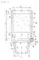
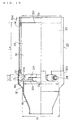
- Fig. 1 is a side cross-sectional view showing an embodiment of a catalytic converter according to the present invention.
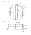
- Figs. 2A and 2B show an embodiment of a honeycomb structure of a honeycomb heater.
- Fig. 2A is a plan view
- Fig. 2B is a side view.
- Fig. 3 is a side cross-sectional view showing another embodiment of a catalytic converter according to the present invention.
- Fig. 4 is a side cross-sectional view showing still another embodiment of a catalytic converter according to the present invention.
- Fig. 5 is a side cross-sectional view showing yet another embodiment of a catalytic converter according to the present invention.
- Fig. 6 is an explanatory view showing an oval.
- Figs. 7A and 7B show another embodiment of a honeycomb structure of a honeycomb heater.
- Fig. 7A is a plan view
- Fig. 7B is a side view.
- Fig. 8 is a plan view showing an embodiment of a holding member.
- Fig. 9 is a partial cross-sectional view showing a circumferential portion of a honeycomb structure of a honeycomb heater.
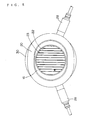
- Fig. 10 is a plan view showing an embodiment of a honeycomb heater to which electrodes are attached.
- Fig. 11 is a plan view showing a state that a honeycomb heater is engaged with a housing.
- Fig. 12 is a chart showing a correlation between a length L 1 in the axial direction and a diameter D 1 with a parameter of a proper oscillation frequency in a honeycomb structure of a honeycomb heater.
- Fig. 13 is an explanatory view showing a method for testing a catalytic converter.
- Fig. 14 is a graph showing an exhausted volume of hydrocarbon per mile in a catalytic converter.
- Figs. 15A and 15B are cross-sectional views of catalytic converters.
- Fig. 15A shows an embodiment of a catalytic converter of the present invention
- Fig. 15B shows an embodiment of a conventional catalytic converter.
- Fig. 16A is a graph showing a thermal property of a honeycomb structure of a honeycomb heater at a central axis.
- Figs. 16B, 16C, 16D, and 16E are graphs showing a thermal property of a honeycomb structure of a catalytic element.
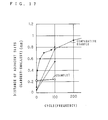
- Fig. 17 is a graph showing a deformation of a honeycomb structure of a honeycomb heater.
- Fig. 18 is a graph showing a correlation between a length L 1 and a diameter D 1 regarding heat capacity of a honeycomb structure of a honeycomb heater.
- Fig. 19 is a side cross-sectional view showing a constitution of a conventional catalytic converter.
- Fig. 1 is a structural explanatory view showing an embodiment of a catalytic converter of the present invention.
- a catalytic converter of the present invention includes a housing 12, a honeycomb heater 20 fixed to inside the housing 12, and a catalytic element 30 fixed to inside the housing 12 and positioned downstream of the honeycomb heater 20.
- the honeycomb heater 20 itself including the honeycomb structure 22 and the catalytic element 30 itself including the honeycomb structure 32 may be the same as conventional ones.
- the honeycomb heater 20 includes a metallic first honeycomb structure 22 having a first partition wall for forming a numerous number of first throughholes, and at least one electrode 28 for electrifying the first honeycomb structure 22.
- the first honeycomb structure 22 has a first inflow end surface 22s through which a fluid such as an exhaust gas flows in the first throughholes and a first outflow end surface 22t though which the fluid flows out of the first throughholes.
- the catalytic element 30 fixed to inside a housing 12 and positioned downstream of the honeycomb heater 20 includes a second honeycomb structure 32 having a second partition wall for forming a numerous number of second throughholes and a catalytic composition loaded on the second honeycomb structure 32.
- the second honeycomb structure 32 has a second inflow end surface 32s through which a fluid such as an exhaust gas flows in the second throughholes and a second outflow end surface 32t through which the fluid flow out of the second throughholes.
- an area of a horizontal cross-section of the honeycomb structure 22 was made smaller than that of the honeycomb structure 32.
- an area of the inflow end surface 32s of a honeycomb structure 32 is 1.2 - 10 times, preferably 1.3 - 5 times, more preferably 1.4 - 3 times, of an area of the outflow end surface 22t or a honeycomb structure 22.
- the length L 2 of the honeycomb structure 32 in the axial direction is long, and a pressure loss upon passing of a fluid such as exhaust gas increases.
- a diameter of the honeycomb structure 22 becomes small, durability (particularly, resistance against vibrations extending over a long period) can be improved. Additionally, the honeycomb structure 22 can be heated for a short period of time after being electrified because the honeycomb structure 22 has a small heat capacity.
- an area of the outflow end surface 22t of a honeycomb structure 22 is preferably 64 cm 2 or less.
- the diameter corresponds to 90 mm or less. More preferably, an area of the outflow end surface 22t of a honeycomb structure 22 is 45 cm 2 or less.
- the diameter corresponds to 76 mm.
- An average of horizontal cross-sections of the honeycomb structure 32 is preferably 1.2 - 10 times of a horizontal cross-section of a honeycomb structure 22, more preferably 1.3 - 5 times, furthermore preferably 1.4 - 3 times.
- horizontal cross-sections of a honeycomb structures 22 and 32 are cross-sections perpendicular to the axial direction 20a of the honeycomb structures 22 and 32.
- Horizontal cross-sections of honeycomb structures 22 and 32 are often formed so as to be parallel to the inflow end surface 22s and 32s and the outflow end surfaces 22t and 32t, respectively.
- An average of horizontal cross-sections of the honeycomb structure 22 is preferably 64 cm 2 or more, more preferably 45 cm 2 or less.
- Figs. 2A and 2B are explanatory views showing an embodiment of the honeycomb structure 22 of the honeycomb heater 20.
- the honeycomb structure 22 may be the same as a conventional one.
- slits 23 are formed in the honeycomb structure 22 so as to block a passage of current.
- slits 23 are formed to be parallel to the axial direction 20a of a honeycomb structure 22.
- an insulating material may be used to block the passage of current.
- At least one electrode 28 for electrifying is provided to the circumferential surface of the honeycomb structure 22.
- the electrode here, means a general term for terminals (including terminals such as a ground for applying a voltage to the heater).
- the electrode 28 is electrically connected to a honeycomb structure by means of a plate 26 or the like.
- a groove 24 is formed around the circumferential surface 22a of the honeycomb structure 22.
- An end of a holding member for fixing the honeycomb structure 22 to the housing 12 has a shape along the shape of the groove 24.
- the groove 24 can be obtained by subjecting a sintered honeycomb structure 22 to cylindrical grinding. Alternatively, when a honeycomb structure is molded by extrusion of a powdered metal, the groove can be previously formed to a compact for the honeycomb structure in various manners.
- a gap G between an outflow end surface 22t of the honeycomb structure 22 and an inflow end surface 32s of the honeycomb structure 32 was widened.
- the gap G is preferably 10 - 50 mm, more preferably 20 - 40 mm. In this range, a thermal loss of an exhaust gas and a temperature rising property in circumferential portion of the honeycomb structure 32 are well balanced.
- an exhaust gas heated by a honeycomb heater 20 can extend in the direction perpendicular to the axial direction 20a of the honeycomb structure 22 until the exhaust gas flows in the honeycomb structure 32 through its inflow end surface 32s, and the circumferential portion 33 of the honeycomb structure 32 can be rapidly heated, thereby improving a responding ability of the circumferential portion 33 of the honeycomb structure 32.
- a heat loss of an exhaust gas can be decreased to a certain degree.
- How much an exhaust gas flew out of the honeycomb structure 22 can extend in the diametrical direction perpendicular to the axial direction 20a of a honeycomb structure 22 until the gas flow into the honeycomb structure 32 depends on a ratio (G/D 1 ) of the gap G to the diameter D 1 of the outflow end surface 22t of the honeycomb structure 22.
- the ratio (G/D 1 ) of the gap G to the diameter D 1 of the outflow end surface 22t of the honeycomb structure 22 is specified to be 0.13 - 0.83.
- the region corresponds to the gap G of 10 mm or more when D 1 is 77 mm or less and the gap G of 50 mm or less when D 1 is 50 mm or less.
- the ratio (G/D 1 ) of the gap G to the diameter D 1 is within the range from 0.26 to 0.67. This range corresponds to the gap G of 20 mm or more when D 1 is 77 mm and the gap G of 40 mm or less when D 1 is 60 mm.
- How much an exhaust gas flew out of the honeycomb structure 22 can extend in the diametrical direction perpendicular to the axial direction 20a of a honeycomb structure 22 until the gas flow into the honeycomb structure 32 also depends on the length L 1 in the axial direction 20a of the honeycomb structure 22.
- a fluid such as an exhaust gas is directed so as to flow in the axial direction 20a of the honeycomb structure when the fluid passes through the throughholes of the honeycomb structure 22. This is particularly remarkable when a speed of a fluid is high.
- a ratio (G/L 1 ) of the gap G to the length L 1 of the honeycomb heater 22 in the axial direction 20a is 0.9 - 6.7. This range corresponds to the gap G of 10 mm or more when the length L 1 of the honeycomb structure 22 in the axial direction 20a is 11 mm and the gap G of 50 mm or less when the length L 1 is 7.5 mm.
- a ratio (G/L 1 ) of the gap to the length L 1 of the honeycomb structure 22 in the axial direction 20a is preferably 1.3 - 5.3.
- the range corresponds to the gap G of 20 mm or more when the length L 1 of the honeycomb structure 22 in the axial direction 22a is 15 mm and the gap G of 40 mm or less when the length L 1 is 7.5 mm.
- a duct 16 is positioned upstream of the honeycomb structure 22.
- an area of the inflow end surface 22s of the honeycomb structure 22 is preferably 1 - 3 times of an area of the outflow end surface 16s of the duct 16, more preferably 1 - 2 times, and furthermore preferably 1 - 1.5 times. Since a diameter of the honeycomb structure 22 can be made small in the present invention, such a structure can be easily obtained.
- a length L 1 of the honeycomb structure 22 in the axial direction 20a is preferably 5 - 15 mm, more preferably 5 - 10 mm, and furthermore preferably 6 - 9 mm.
- Fig. 3 shows an embodiment of a catalytic converter of the present invention.
- the honeycomb structure 22 is fixed to a housing 12 by means of a holding member 13.
- a shock absorbing member 40 is positioned between the honeycomb structure 32 and a housing 14. At both ends of the shock absorbing member 40, the honeycomb structure 32 is fixed to the housing 14 by means of a holding member 34 having a shape of a ring.
- an angle between an axial direction of an electrode 28 and an axial direction 20a of a honeycomb structure 22 is 90°.
- the angle ⁇ is specified to be 135°.
- an area of the inflow end surface 32s of the honeycomb structure 32 is 1.2 - 10 times of an area of the outflow end surface 22t of the honeycomb structure 22. Accordingly, the electrode 28 came to be able to be arranged so as to make an angle ⁇ of 90° - 170° by specifying a diameter of the honeycomb structure 22 to be smaller than that of the honeycomb structure 32.
- a conductive member 26 having a shape of a plate ensures conductivity between a honeycomb structure 22 and an electrode 28.
- the angle ⁇ between an axial direction 20a of the honeycomb structure 22 and an axial direction of the electrode 28 is preferably 90° - 170°, more preferably 120° - 150°.
- a horizontal cross-section of the honeycomb structure 22 has a shape of an oval.
- an oval 60 has a shape consisting of a pair of parallel straight lines 61 and a pair of arcs 62 (typically half circles), both of them are combined with each other in their end portion.
- a diameter D 1 of the outflow end surface 25t of the honeycomb structure 22 in the oval means a distance between a pair of the straight lines 61, i.e., a shorter diameter E 1 . This is because a vibration resistance of the honeycomb structure 22 depends on the shorter diameter when slits 23 are formed in the honeycomb structure 22.
- a diameter D 2 of the inflow end surface 32s of the honeycomb structure 32 is longer than not only the shorter diameter E 1 but also the longer diameter E 2 of the honeycomb structure 22.
- the diameter D 2 of the inflow end surface 32s of the honeycomb structure 32 may be shorter than the longer diameter E 2 of the honeycomb structure 22.
- a diameter of the outflow end surface of the duct 16 is shorter than the shorter diameter E 1 and the longer diameter E 2 of the honeycomb structure 22.
- a shape of a horizontal cross-section of a honeycomb structure 22 may be oval. When it is oval, the shorter diameter is a diameter D 1 of the outflow end surface 22t of the honeycomb structure 22.
- a mechanical structure of a honeycomb structure 22 in a honeycomb heater 22 is basically the same as that of a honeycomb structure 32 except for slits 23.
- a shape of a horizontal cross-section of throughholes in honeycomb structures 22 and 33 is not particularly limited, a shape flexible with expansion and contraction, for example, a hexagon or a polygon having more sides than a hexagon, and a corrugation is preferable.
- a cell density i.e., a density of throughholes in honeycomb structures 22 and 32 is not particularly limited. However, in view of thermal conductivity, catalytic purifying efficiency, etc., the density is preferably 100 - 800 cell/inch 2 , more preferably 200 - 600 cell/inch 2 . When the density exceeds 800 cell/inch 2 , a problem in pressure loss of a fluid is caused particularly in the honeycomb structure 32.
- a foil type or an extrusion type can be employed as the honeycomb structures 22 and 32.
- a foil type of a honeycomb structure is formed by winding up a corrugated foil obtained by rolling.
- An extrusion type of a honeycomb structure is formed by extruding a powdered metal. However, an extrusion type is preferable in view of durability.
- the surface of the partition walls of the honeycomb structure 22 may be coated with a catalytic composition.
- a thickness of a partition wall of the honeycomb structure 32 is desirably 0.14 mm (5.5 mil) or less so that the honeycomb structure 32 has small heat capacity and a temperature rising property of the honeycomb structure 32 is enhanced as much as possible.
- any metallic material which is heated by electrifying As a material for the honeycomb structure 22, any metallic material which is heated by electrifying. Since the honeycomb structure 22 is exposed to an exhaust gas of an automobile, or the like, having a high temperature, an Fe-Cr-Al type of alloy is preferable in view of heat resistance and oxidation resistance.
- a material for the honeycomb structure 32 may be a ceramic or a metal. When the honeycomb structure 32 is metallic, the material may be the same as that of the honeycomb structure 22.
- a catalytic composition to be loaded on the honeycomb structures 22 and 32 includes a carrier having a large surface area and a catalytic activated substance to be loaded on the carrier.
- a carrier may be, for example, a powdered or a granulated material of ⁇ -Al 2 O 3 type, TiO 2 type, SiO 2 -Al 2 O 3 type, perovskite type.
- a catalytic activated substance may be a noble metal such as platinum (Pt), palladium (Pd), and Rhodium (Rh), a base metal such as Cu, Ni, Cr, and Co.
- a honeycomb heater 20 and a catalytic element 30 may be fixed to metallic housings 12 and 14 by means of a metallic holding member 13.
- the holding member 13 has a flexible structure like a spring structure so as to absorb displacement occurring in a diametrical direction of the honeycomb structure.
- the holding member 13 further has a structure having high resistance and strength in the gas flow direction for fixing a honeycomb heater 20 against displacement occurring in the gas flow direction.
- a structure of the electrode 28 for electrifying the honeycomb structure 22 constituting a honeycomb heater 20 is preferably connected with the honeycomb structure 22 and housing 12 by means of a connecting member and a shock absorbing member because a displacement of the honeycomb heater 20 in a direction of a radius can be absorbed.
- Fe powder having an average diameter of 44 ⁇ m or less, Cr-30Al powder (wt%), Fe-50Al powder (wt%), Fe-20B powder (wt%) and Y 2 O 3 powder were mixed together so as to have a mixture having a composition of Fe-12Cr-10Al-0.05B-0.5Y 2 O 3 .
- Methyl cellulose of 4g and oleic acid of 1g were added to the mixture as an organic binder and an antioxidant, respectively. Thus, a base was prepared. Then, a honeycomb compact having a desired size was obtained by extrusion molding.
- two plates 26 each having a thickness of 2mm, a width of 7.6mm, and length of 12 mm, and the same composition as the honeycomb compact was produced and connected to the circumferential surface of the honeycomb compact.
- the honeycomb compact was dried at 90°C for 16 hours, and subsequently kept at 1325°C for two hours in a hydrogen atmosphere so as to sinter.
- honeycomb structures 22 each having dimensions shown in Tables 1, 2, and 3 were obtained in the aforementioned manner. Any of the honeycomb structures 22 in Examples 1 - 7 had a thickness of a partition wall of 0.1 mm, a hexagonal shape of a horizontal cross-section of each throughhole, and a cell density of 450 cells/inch 2 .
- a groove 24 having a width of 1.8 mm and a depth of 5 mm was formed on the circumferential surface of each honeycomb structure 22 by a cylindrical grinder.
- slits 23 were formed by grinding with a diamond saw in a direction parallel to the axes of the throughholes so that 4 cells might be present between each two adjacent slits.
- the honeycomb structures 22 were then subjected to a thermal treatment at 1150°C for 30 minutes in the air so as to obtain the honeycomb structure 22 shown in Figs. 7A and 7B.
- Example 1 D 1 (mm) D 2 (mm) (D 2 /D 1 ) 2 ⁇ D 1 2 /4 (cm 2 )
- Example 1 75.0 91.5 1.488 44.179
- Example 4 70.0 100.0 2.041 38.485
- Example 5 63.0 91.5 2.109 31.173
- Example 6 75.0 105.0 1.960 44.179
- Example 7 88.0 91.5 1.081 60.821 Comparative Example 88.0 91.5 1.081 60.821
- Table 2 D 1 (mm) L 1 (mm) G (mm) G/D 1 G/L 1
- Example 1 75.0 8.0 30.4 0.405 3.80
- Example 2 63.0 9.8 25.0 0.397 2.55
- Example 4 70.0 8.0 30.0 0.429 3.75
- Example 5 63.0 8.0 30.0 0.476 3.75
- Example 5
- ⁇ -Al 2 O 3 powder and CeO 2 powder were mixed so as to have a weight ratio of 7 : 3, respectively.
- To the mixture were added water and a very small amount of nitric acid. Then, the mixture was ground in a wet method so as to prepare a slurry for loading.
- a wash coat layer was formed on the honeycomb structure 10 with the slurry for loading in a dipping process. Then, the wash coat layer is dried, and fired at 700°C so as to coat ⁇ -Al 2 O 3 powder and CeO 2 therewith.
- platinum (Pt) and Rhodium (Rh) were loaded by immersing honeycomb structure 10 for about 2 minutes in an aqueous solution containing chloroplatinic acid and rhodium nitrate and so that a molar ratio of platinum and rhodium is 5:1 and a total loaded amount of 40 g/ft 3 .
- a honeycomb structure 22 was fixed to a housing 12 by means of two holding members 13.
- a holding member 13 has a half-ringed portion 13a and leg portions 13b fixed to the circumferential surface of the half-ringed portion 13a.
- Two half-ringed portions 13a form a shape of a ring.
- the half-ringed portion 13a has a shape of a half circular having a thickness of 1.5mm and a difference between the inner diameter and the outer diameter of 4.0mm.
- Each of the six leg portions 13b has a thickness of 1.5mm, width of 8mm, and length of 18mm.
- An insulating coat 13c was coated on the half-ringed portion 13a of the holding member 13.
- the insulating coat 13c may be a coat in which a heat resistant inorganic material such as glass (crystallized glass), ceramic, cement, or the like, by means of enameling, irradiating, ceramic coating, cement coating, etc. Though it is not shown in Fig. 9, an insulating coat may be coated on the surface forming a groove 24 of a honeycomb structure 22.
- a spacer having a thickness of 0.8mm was inserted into a portion except for a groove 24 of a slit 23 formed in the honeycomb structure 22 and was held temporarily.
- the groove 24 was filled with an inorganic cement 13d, two holding members 13 were inserted there, the honeycomb heater was dried at 100°C for one hour and at 300°C for one hour in the air to be fixed.
- the inorganic cement 13d a bond #96 containing SiO 2 -Al 2 O 3 as a main component produced by Nissan Chemical Industries, Ltd. was used.
- the spacer was released, connecting portions of two holding members 13 were connected by welding so as to have a ringed shape shown in Fig. 10.
- a connecting member 13d there may be used a heat resistant inorganic cement of Al 2 O 3 , ZrO 2 , SiO 2 -Al 2 O 3 or the like.
- An electrode 28 having a wire was provided with a conductive plate (connecting member) of SUS4O9 having a thickness of 1.0 mm, a width of 8 mm, and a length of 41.5 mm, the plate being arched with R of 46 mm in the direction of the length.
- the electrode 28 was fixed to the honeycomb structure 22 by welding one end of a conductive plate 29 is welded to a plate portion 26 of the honeycomb structure 22.
- honeycomb heater 20 shown in Fig. 10 was engaged with a housing 12 (SUS409, thickness of 1.5mm). Leg portions 13b of a holding member and a circumferential portion of the electrode 28 having a wire were fixed to the housing by welding.
- a duct (SUS409, thickness of 1.5mm) 16 was fixed to the housing 12 by welding so as to have a gap of 2 mm between the honeycomb structure 22 and the duct 16.
- any of the honeycomb structures 32 in Examples 1-7 has a columnar shape made of cordierite, has a thickness of a partition wall of 0.139 mm, and has a square shape of a horizontal cross-section of a throughhole.
- a cell density was 350 cell/inch 2
- Examples 3 a cell density of 600 cell/inch 2 .
- An outer diameter D 2 and a length L 2 of an axial direction are shown in Tables 1 - 3.
- a catalytic component was loaded on a honeycomb structure in the same manner as in honeycomb structure 20.
- a shock absorbing member 40 made of a mat [Interam (trade name) produced by 3M] was wound around the honeycomb structure 32.
- the honeycomb structure 32 was inserted into a housing (SUS310S, thickness of 1.5mm) 14 by pressing and pressed by retainer rings (holding members) 34 from both end surface sides and welded to the housing 14.
- a catalytic converter was obtained by fixing thus obtained catalytic unit 31 by welding so that a gap between an outflow end surface of a heater unit 21 and the retainer rings 34 has a predetermined thickness.
- Example 7 dimensions of the honeycomb structure 22 are the same as those in Comparative Example. However, a gap G in Example 7 is 30 mm longer than that in Comparative Example.
- a proper oscillation frequency of a honeycomb structure 22 is calculated by the following formulae.
- an obtained honeycomb unit 21 and a catalytic unit 31 are connected to an engine 50 by means of ducts 52 and 16.
- a main catalytic unit 56 is connected downstream of the catalytic unit 31. So called three-way catalyst is loaded on the main catalytic unit 56.
- the obtained catalytic converter was subjected to a 100-hour acceleration durability test, in which the catalytic converter was exposed to a temperature of 750°C for 60 minutes with using an engine exhaust gas and with five seconds of fuel cut. The cycle was repeated for 100 hours.
- a catalytic converter was positioned 750mm away from an exhaust gas. Downstream of the catalytic converter was disposed the main catalytic unit 56 having a 1.7-liter capacity (already subjected to a 100-hour acceleration durability test).
- a heater unit 21 and a catalytic unit 31 were fixed to a housing by welding.
- a secondary air introducing hole is positioned 150 mm away from the inflow end surface of a honeycomb heater 20.
- Example 1 it is understandable by comparing Example 1 and Comparative Example that an exhaust volume of HC decreases by increasing a gap G.
- An exhaust volume of HC in Example 2 is a little higher than that in a Comparative Example.
- a volume of a honeycomb structure 32 in Example 2 is 484 cm 3 , which is about 20% smaller than a volume (577 cm 3 ) of a honeycomb structure 32 of a Comparative Example. If the difference of the volumes is considered, it can be thought that a catalytic converter in Example 2 has more improved purification ability than a catalytic converter in Comparative Example.
- Figs. 15A, 15B, 16A, 16B, 16C, 16D, and 16E relate to a measurement of a temperature-rising property of a honeycomb structures 22 and 32 when a catalytic converter is electrified.
- a full line show a temperature in Example 1 of Fig. 15A
- a broken line show a temperature in Comparative Example of Fig. 15B.
- Fig. 16A shows results of measuring temperatures in the center of a honeycomb structure 22.
- Figs. 16B, 16C, 16D, and 16E show results of measuring temperatures in the positions of Om, 33mm, 40mm and 45mm, respectively, from the center toward the circumference in a horizontal cross-section taken in the position of lomm from an inflow end surface 32s towards an axis.
- a radius of a honeycomb structure 32 is 45.8 mm in Example 1 and Comparative Example.
- Figs. 16B and 16C show that a temperature-rising property in the central portion of a honeycomb structure 32 in both Example 1 and Comparative Example.
- Figs. 16D and 16E show that a temperature does not rise in a short period of time in a peripheral portion 33 of the honeycomb structure 32 in Comparative Example, while in Example 1, a temperature rises quickly.
- an internal combustion engine For first one minute, an internal combustion engine is put in motion in an idling condition, and simultaneously an electric power is increased from zero to a predetermined value. Then, the power supply is stopped, and for the next 20 minutes, the internal combustion engine is put in motion under a severe driving condition with a rated number of revolution. For the next one minute, the internal combustion engine is put in motion in an idling condition. Then, for the next 15 minutes, the internal combustion engine is stopped. The cycle was repeated, and a honeycomb structure 22 of a honeycomb heater 20 was measured for deformation. In order to express a volume of deformation of a honeycomb structure 22, a value obtained by deducting a shortest distance of adjacent slits from the longest one was used as a parameter.
- Fig. 17 shows a movement of deformation of the honeycomb structure 22. From Fig. 17, it is understood that a honeycomb structure 22 in Example 1, having a diameter of 75 mm has less deformation than a honeycomb structure 22 in Comparative Example, having a diameter of 88 mm.
- Fig. 18 shows a heat capacity of a honeycomb structure 22.
- the heat capacity was obtained under the conditions that a thickness of a partition wall is 1.0 mm, a cell density is 450 cell/inch 2 , a catalytic composition is loaded on a honeycomb structure at a rate of 0.09g/cm 3 .
- Fig. 18 shows that a heat capacity decreases according to a decrease of a diameter D 1 of a honeycomb structure 22.
- a honeycomb structure 22 in Example 1 i.e., a honeycomb structure having a diameter D 1 of 75mm and a length L 1 of 8.0mm has a heat capacity of 20J/C°.
- a honeycomb structure 22 in Comparative Example i.e., a honeycomb structure having a diameter D 1 of 88mm and a length L 1 of 7.6mm has a heat capacity of 30J/C°.
- the honeycomb structure has a temperature rise of 67C° per minute.
- a honeycomb structure 22 having a diameter D 1 of 75mm and a length of L 1 of 8.0mm has a heat capacity of 23J/C°, and when an electric power of 2KW is supplied, the honeycomb structure has a temperature rise of 87C° per minute.
- an area of a horizontal cross-section of a honeycomb structure of a honeycomb heater is made smaller than a honeycomb structure of a catalytic element, thereby improving a durability of a honeycomb structure, particularly resistance against vibrations extending over a long period of time, with maintaining an exhaust gas purification ability under severe conditions during driving an automobile, or the like.
- temperature of a honeycomb heater can be raised up for a short period of time.
- a distance between a honeycomb heater and a catalytic element is enlarged more than predetermined distance, thereby improving a response of a catalytic element to a temperature rise in a peripheral portion of a honeycomb structure.
Landscapes
- Chemical & Material Sciences (AREA)
- Engineering & Computer Science (AREA)
- Chemical Kinetics & Catalysis (AREA)
- Combustion & Propulsion (AREA)
- Mechanical Engineering (AREA)
- General Engineering & Computer Science (AREA)
- Health & Medical Sciences (AREA)
- Toxicology (AREA)
- Exhaust Gas After Treatment (AREA)
- Exhaust Gas Treatment By Means Of Catalyst (AREA)
- Catalysts (AREA)
Applications Claiming Priority (3)
| Application Number | Priority Date | Filing Date | Title |
|---|---|---|---|
| JP7082/96 | 1996-01-19 | ||
| JP708296 | 1996-01-19 | ||
| JP8007082A JPH09192453A (ja) | 1996-01-19 | 1996-01-19 | 触媒コンバーター |
Publications (2)
| Publication Number | Publication Date |
|---|---|
| EP0785341A1 true EP0785341A1 (de) | 1997-07-23 |
| EP0785341B1 EP0785341B1 (de) | 1999-12-22 |
Family
ID=11656177
Family Applications (1)
| Application Number | Title | Priority Date | Filing Date |
|---|---|---|---|
| EP97300212A Expired - Lifetime EP0785341B1 (de) | 1996-01-19 | 1997-01-15 | Katalytischer Umwandler |
Country Status (4)
| Country | Link |
|---|---|
| US (1) | US5888456A (de) |
| EP (1) | EP0785341B1 (de) |
| JP (1) | JPH09192453A (de) |
| DE (1) | DE69700964T2 (de) |
Cited By (2)
| Publication number | Priority date | Publication date | Assignee | Title |
|---|---|---|---|---|
| EP1111212A3 (de) * | 1999-12-21 | 2003-07-23 | Ford Global Technologies, Inc. | Abgasreinigungssystem eines Magermotors |
| EP2559487A4 (de) * | 2010-04-14 | 2015-06-24 | Toyota Motor Co Ltd | Elektrisch beheizter katalysator und herstellungsverfahren dafür |
Families Citing this family (22)
| Publication number | Priority date | Publication date | Assignee | Title |
|---|---|---|---|---|
| JP3709953B2 (ja) * | 1997-09-12 | 2005-10-26 | 本田技研工業株式会社 | 内燃機関の排気浄化装置 |
| JPH1181999A (ja) * | 1997-09-12 | 1999-03-26 | Honda Motor Co Ltd | 内燃機関の排気浄化装置 |
| US6056631A (en) * | 1997-10-09 | 2000-05-02 | Advanced Micro Devices, Inc. | Chemical mechanical polish platen and method of use |
| US6616909B1 (en) * | 1998-07-27 | 2003-09-09 | Battelle Memorial Institute | Method and apparatus for obtaining enhanced production rate of thermal chemical reactions |
| US6479428B1 (en) * | 1998-07-27 | 2002-11-12 | Battelle Memorial Institute | Long life hydrocarbon conversion catalyst and method of making |
| US6440895B1 (en) * | 1998-07-27 | 2002-08-27 | Battelle Memorial Institute | Catalyst, method of making, and reactions using the catalyst |
| DE10043865A1 (de) * | 2000-09-04 | 2002-03-14 | Daimler Chrysler Ag | Verfahren zur Herstellung eines Katalysators |
| WO2003031371A1 (fr) * | 2001-10-02 | 2003-04-17 | Ngk Insulators, Ltd. | Corps structural en nid d'abeille et procede de fabrication |
| US20050036923A1 (en) * | 2003-07-31 | 2005-02-17 | Brisbin Ronald S. | End cone construction for catalytic converters and method for making same |
| JP4645297B2 (ja) * | 2005-05-13 | 2011-03-09 | 株式会社豊田自動織機 | 排気微粒子浄化装置 |
| JP2009299580A (ja) * | 2008-06-13 | 2009-12-24 | Toyota Motor Corp | 内燃機関の排気浄化装置 |
| JP5590127B2 (ja) * | 2010-08-23 | 2014-09-17 | トヨタ自動車株式会社 | 電気加熱式触媒 |
| WO2012133405A1 (ja) * | 2011-03-29 | 2012-10-04 | 日本碍子株式会社 | 熱交換部材、および熱交換器 |
| JP6703872B2 (ja) * | 2016-03-28 | 2020-06-03 | 日本碍子株式会社 | ヒータ及びそのヒータを備えるハニカム構造体 |
| DE102019110359A1 (de) * | 2019-04-18 | 2020-10-22 | Faurecia Emissions Control Technologies, Germany Gmbh | Abgasbehandlungseinrichtung und Fahrzeug |
| JP7422635B2 (ja) * | 2020-09-23 | 2024-01-26 | 日本碍子株式会社 | 電気加熱式担体、排気ガス浄化装置及び電気加熱式担体の製造方法 |
| WO2022115349A1 (en) * | 2020-11-30 | 2022-06-02 | Corning Incorporated | Electrically powered catalyst heater for fluid treatment systems |
| EP4334581A1 (de) * | 2021-05-03 | 2024-03-13 | Corning Incorporated | Elektrische heizelemente für abgasnachbehandlungssysteme und -anordnungen |
| DE102021122577A1 (de) * | 2021-09-01 | 2023-03-02 | Purem GmbH | Abgasanlage |
| DE102022114368A1 (de) | 2022-06-08 | 2023-12-14 | Purem GmbH | Abgasheizer |
| DE102022121593B4 (de) | 2022-08-25 | 2024-05-23 | Tenneco Gmbh | Heizelement mit integrierter Elektrode |
| CN117180977B (zh) * | 2023-10-26 | 2024-08-02 | 深碳科技(深圳)有限公司 | 一种固态胺解吸装置、固态胺碳捕集系统 |
Citations (6)
| Publication number | Priority date | Publication date | Assignee | Title |
|---|---|---|---|---|
| US5063029A (en) | 1990-04-12 | 1991-11-05 | Ngk Insulators, Ltd. | Resistance adjusting type heater and catalytic converter |
| JPH04339122A (ja) * | 1991-05-15 | 1992-11-26 | Ngk Spark Plug Co Ltd | 触媒ヒータ付き排気浄化装置 |
| US5202548A (en) | 1991-01-16 | 1993-04-13 | Ngk Insulators, Ltd. | Resistance adjusting type heater |
| EP0579415A1 (de) * | 1992-07-11 | 1994-01-19 | Johnson Matthey Public Limited Company | Stromaufwärts eines Katalysators angeordneter Erhitzer |
| US5323607A (en) * | 1992-05-14 | 1994-06-28 | Toyota Jidosha Kabushiki Kaisha | Exhaust emission control system and method having improved heating control function for catalyst |
| DE4302039A1 (de) * | 1993-01-26 | 1994-07-28 | Emitec Emissionstechnologie | Katalytischer Konverter mit elektrischer Beheizung |
Family Cites Families (4)
| Publication number | Priority date | Publication date | Assignee | Title |
|---|---|---|---|---|
| US3768982A (en) * | 1971-06-22 | 1973-10-30 | Ford Motor Co | Catalytic converter with electrically preheated catalyst |
| JP2818473B2 (ja) * | 1990-06-29 | 1998-10-30 | 日本碍子株式会社 | 自動車排ガス浄化用触媒コンバーター装置及び自動車排ガスの浄化方法 |
| DE4035971A1 (de) * | 1990-11-12 | 1992-05-14 | Emitec Emissionstechnologie | Beheizbare katalysatoranordnung fuer die abgasreinigung von verbrennungsmotoren |
| JP3142717B2 (ja) * | 1994-06-16 | 2001-03-07 | 日本碍子株式会社 | ヒーターユニット及び触媒コンバーター |
-
1996
- 1996-01-19 JP JP8007082A patent/JPH09192453A/ja active Pending
- 1996-12-20 US US08/770,777 patent/US5888456A/en not_active Expired - Fee Related
-
1997
- 1997-01-15 DE DE69700964T patent/DE69700964T2/de not_active Expired - Lifetime
- 1997-01-15 EP EP97300212A patent/EP0785341B1/de not_active Expired - Lifetime
Patent Citations (6)
| Publication number | Priority date | Publication date | Assignee | Title |
|---|---|---|---|---|
| US5063029A (en) | 1990-04-12 | 1991-11-05 | Ngk Insulators, Ltd. | Resistance adjusting type heater and catalytic converter |
| US5202548A (en) | 1991-01-16 | 1993-04-13 | Ngk Insulators, Ltd. | Resistance adjusting type heater |
| JPH04339122A (ja) * | 1991-05-15 | 1992-11-26 | Ngk Spark Plug Co Ltd | 触媒ヒータ付き排気浄化装置 |
| US5323607A (en) * | 1992-05-14 | 1994-06-28 | Toyota Jidosha Kabushiki Kaisha | Exhaust emission control system and method having improved heating control function for catalyst |
| EP0579415A1 (de) * | 1992-07-11 | 1994-01-19 | Johnson Matthey Public Limited Company | Stromaufwärts eines Katalysators angeordneter Erhitzer |
| DE4302039A1 (de) * | 1993-01-26 | 1994-07-28 | Emitec Emissionstechnologie | Katalytischer Konverter mit elektrischer Beheizung |
Non-Patent Citations (1)
| Title |
|---|
| PATENT ABSTRACTS OF JAPAN vol. 17, no. 186 (M - 1395) 12 April 1993 (1993-04-12) * |
Cited By (2)
| Publication number | Priority date | Publication date | Assignee | Title |
|---|---|---|---|---|
| EP1111212A3 (de) * | 1999-12-21 | 2003-07-23 | Ford Global Technologies, Inc. | Abgasreinigungssystem eines Magermotors |
| EP2559487A4 (de) * | 2010-04-14 | 2015-06-24 | Toyota Motor Co Ltd | Elektrisch beheizter katalysator und herstellungsverfahren dafür |
Also Published As
| Publication number | Publication date |
|---|---|
| DE69700964T2 (de) | 2000-06-15 |
| DE69700964D1 (de) | 2000-01-27 |
| EP0785341B1 (de) | 1999-12-22 |
| US5888456A (en) | 1999-03-30 |
| JPH09192453A (ja) | 1997-07-29 |
Similar Documents
| Publication | Publication Date | Title |
|---|---|---|
| EP0785341B1 (de) | Katalytischer Umwandler | |
| EP0687807B1 (de) | Heizungseinheit und katalytischer Umwandler | |
| EP0618353B2 (de) | Heizeinheit | |
| EP0661097B1 (de) | Honigwabenheizgerät | |
| EP0483708B1 (de) | Katalytischer Umwandler in Verbundbauweise | |
| US5174968A (en) | Structure for electrically heatable catalytic core | |
| JP3001281B2 (ja) | ハニカムモノリスヒータ | |
| KR100626194B1 (ko) | 벌집형 구조체 및 그것을 수납하여 이루어지는 캐닝 구조체 | |
| JP3040510B2 (ja) | ハニカムヒーター | |
| CA2040289C (en) | Resistance adjusting type heater and catalytic converter | |
| JPH05202743A (ja) | 電気的に加熱し得る触媒変換器の上手にあるコリメーター | |
| JP3210508B2 (ja) | ハニカムヒーター | |
| EP0768107A1 (de) | Wabenförmiges Heizgerät mit Parallelschaltungen | |
| US5399841A (en) | Honeycomb heater | |
| EP0661421B1 (de) | Honigwabenheizgerät | |
| JP3179651B2 (ja) | ヒーターユニット | |
| CA2049634A1 (en) | Electrically heated catalytic converter | |
| JPH09253504A (ja) | 熱疲労特性に優れるヒーターユニット | |
| JP2001252573A (ja) | ハニカムヒーター | |
| JP2003278537A (ja) | 触媒コンバータ |
Legal Events
| Date | Code | Title | Description |
|---|---|---|---|
| PUAI | Public reference made under article 153(3) epc to a published international application that has entered the european phase |
Free format text: ORIGINAL CODE: 0009012 |
|
| AK | Designated contracting states |
Kind code of ref document: A1 Designated state(s): DE FR GB |
|
| 17P | Request for examination filed |
Effective date: 19970822 |
|
| 17Q | First examination report despatched |
Effective date: 19980713 |
|
| GRAG | Despatch of communication of intention to grant |
Free format text: ORIGINAL CODE: EPIDOS AGRA |
|
| GRAG | Despatch of communication of intention to grant |
Free format text: ORIGINAL CODE: EPIDOS AGRA |
|
| GRAH | Despatch of communication of intention to grant a patent |
Free format text: ORIGINAL CODE: EPIDOS IGRA |
|
| GRAH | Despatch of communication of intention to grant a patent |
Free format text: ORIGINAL CODE: EPIDOS IGRA |
|
| GRAA | (expected) grant |
Free format text: ORIGINAL CODE: 0009210 |
|
| AK | Designated contracting states |
Kind code of ref document: B1 Designated state(s): DE FR GB |
|
| REF | Corresponds to: |
Ref document number: 69700964 Country of ref document: DE Date of ref document: 20000127 |
|
| ET | Fr: translation filed | ||
| PLBE | No opposition filed within time limit |
Free format text: ORIGINAL CODE: 0009261 |
|
| STAA | Information on the status of an ep patent application or granted ep patent |
Free format text: STATUS: NO OPPOSITION FILED WITHIN TIME LIMIT |
|
| 26N | No opposition filed | ||
| REG | Reference to a national code |
Ref country code: GB Ref legal event code: IF02 |
|
| PGFP | Annual fee paid to national office [announced via postgrant information from national office to epo] |
Ref country code: GB Payment date: 20050105 Year of fee payment: 9 |
|
| PGFP | Annual fee paid to national office [announced via postgrant information from national office to epo] |
Ref country code: FR Payment date: 20050125 Year of fee payment: 9 |
|
| PG25 | Lapsed in a contracting state [announced via postgrant information from national office to epo] |
Ref country code: GB Free format text: LAPSE BECAUSE OF NON-PAYMENT OF DUE FEES Effective date: 20060115 |
|
| PG25 | Lapsed in a contracting state [announced via postgrant information from national office to epo] |
Ref country code: FR Free format text: LAPSE BECAUSE OF NON-PAYMENT OF DUE FEES Effective date: 20060131 |
|
| GBPC | Gb: european patent ceased through non-payment of renewal fee |
Effective date: 20060115 |
|
| REG | Reference to a national code |
Ref country code: FR Ref legal event code: ST Effective date: 20060929 |
|
| PGFP | Annual fee paid to national office [announced via postgrant information from national office to epo] |
Ref country code: DE Payment date: 20110131 Year of fee payment: 15 |
|
| PG25 | Lapsed in a contracting state [announced via postgrant information from national office to epo] |
Ref country code: DE Free format text: LAPSE BECAUSE OF NON-PAYMENT OF DUE FEES Effective date: 20120801 |
|
| REG | Reference to a national code |
Ref country code: DE Ref legal event code: R119 Ref document number: 69700964 Country of ref document: DE Effective date: 20120801 |