EP0785349A2 - Méthode et dispositif pour le diagnostic de défaillances des injecteurs d'un système d'injection à haute pression de moteur à combustion interne - Google Patents
Méthode et dispositif pour le diagnostic de défaillances des injecteurs d'un système d'injection à haute pression de moteur à combustion interne Download PDFInfo
- Publication number
- EP0785349A2 EP0785349A2 EP97100613A EP97100613A EP0785349A2 EP 0785349 A2 EP0785349 A2 EP 0785349A2 EP 97100613 A EP97100613 A EP 97100613A EP 97100613 A EP97100613 A EP 97100613A EP 0785349 A2 EP0785349 A2 EP 0785349A2
- Authority
- EP
- European Patent Office
- Prior art keywords
- acceleration signal
- amplitude
- predetermined reference
- comparing
- angle value
- Prior art date
- Legal status (The legal status is an assumption and is not a legal conclusion. Google has not performed a legal analysis and makes no representation as to the accuracy of the status listed.)
- Granted
Links
Images

Classifications
-
- F—MECHANICAL ENGINEERING; LIGHTING; HEATING; WEAPONS; BLASTING
- F02—COMBUSTION ENGINES; HOT-GAS OR COMBUSTION-PRODUCT ENGINE PLANTS
- F02D—CONTROLLING COMBUSTION ENGINES
- F02D41/00—Electrical control of supply of combustible mixture or its constituents
- F02D41/22—Safety or indicating devices for abnormal conditions
- F02D41/221—Safety or indicating devices for abnormal conditions relating to the failure of actuators or electrically driven elements
-
- F—MECHANICAL ENGINEERING; LIGHTING; HEATING; WEAPONS; BLASTING
- F02—COMBUSTION ENGINES; HOT-GAS OR COMBUSTION-PRODUCT ENGINE PLANTS
- F02D—CONTROLLING COMBUSTION ENGINES
- F02D41/00—Electrical control of supply of combustible mixture or its constituents
- F02D41/30—Controlling fuel injection
- F02D41/38—Controlling fuel injection of the high pressure type
- F02D41/3809—Common rail control systems
Definitions
- the present invention relates to a method and unit for diagnosing malfunctioning of the injectors of an internal combustion engine high-pressure injection system.
- high-pressure injection systems comprise a number of injectors for supplying fuel to an internal combustion engine.
- the above phenomena may result in serious damage to the engine, e.g. to the connecting rod, piston or the injector nozzles.
- a method of diagnosing malfunctioning of injectors of an internal combustion engine high-pressure injection system comprising the steps of:
- a unit for diagnosing malfunctioning of injectors of an internal combustion engine high-pressure injection system characterized by comprising an acceleration sensor generating an acceleration signal related to the intensity of vibration in an engine; comparing means connected to said acceleration sensor to compare said acceleration signal with reference values; and fault detecting means for determining a fault condition in the event of a predetermined relationship between said acceleration signal and said reference values.
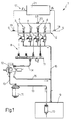
- Number 1 in Figure 1 indicates a high-pressure injection system for a diesel engine 2 comprising a block 3, cylinders 4, a drive shaft 5 (shown schematically), and a camshaft 6 (also shown schematically).
- Injection system 1 comprises a number of injectors 7 for supplying fuel to cylinders 4 of engine 2, and in turn supplied by a known "common rail" supply circuit 8.
- Supply circuit 8 comprises a fuel tank 9; a delivery pump 10 housed inside tank 9; a known common rail 11; a radial-piston pump 12 connected to delivery pump 10 by a low-pressure delivery line 13, and to common rail 11 by a high-pressure delivery line 14; and a fuel filter 15 located along low-pressure delivery line 13.
- Each of injectors 7 and radial-piston pump 12 are also connected to tank 9 by drain lines 16 for feeding part of the fuel, used during operation of the injectors and the pump, back into tank 9 in known manner and therefore not described in detail.
- Injection system 1 also comprises a diagnostic unit 17 for detecting malfunctioning of injection system 1.
- Diagnostic unit 17 comprises a first known position sensor 18 located on drive shaft 5 to generate a first position signal ⁇ 1 indicating the angular position of drive shaft 5 (drive angle A); a second known position sensor 19 located on camshaft 6 to generate a second position signal ⁇ 2 indicating the angular position of camshaft 6; a known acceleration sensor 20 located on block 3 of engine 2 to generate an acceleration signal S related to the intensity of vibration present on block 3 and caused by combustion of engine 2; and an electronic central control unit 21 receiving acceleration signal S and position signals ⁇ 1 and ⁇ 2 , and which implements the diagnostic operations described in detail later on with reference to Figure 2.
- the invention is based on the fact that, when one or more injectors are jammed in the open position, this results in abnormal combustion of engine 2, in turn resulting in far greater vibration as compared with correct combustion; and that such vibration is present even before the instant at which the injection start command is given.
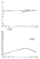
- Figures 3 and 4 show graphs of acceleration signal S and the pressure P inside cylinder 4 as a function of drive angle A, and under correct operating conditions of injector 7; while Figures 5 and 6 show graphs of the same quantities with injector 7 jammed in the open position.
- an injector 7 jammed in the open position causes a pressure peak inside cylinder 4, and a considerable increase in the intensity of vibration on block 3 of engine 2.
- acceleration signal S begins oscillating well in advance with respect to correct operation of the injector, i.e. even before the instant at which the injection start command is given.
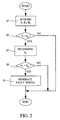
- the crossover angle A o at which acceleration signal S exceeds predetermined reference amplitude value S th is determined (block 27).
- Crossover angle A o is then compared with a predetermined reference angle value A th equal or related to the drive angle at which fuel is injected into each cylinder 4 under normal combustion conditions (block 28).
- crossover angle A o is less than predetermined reference angle value A th (YES output of block 28)
- a jammed-open injector 7 is diagnosed, and a fault signal is generated (block 29) to indicate malfunctioning of an injector 7.
- NO output of block 28 the diagnosis is terminated.
- diagnosis performed in blocks 25-29 is repeated cyclically to continually monitor operation of injection system 1.
- the reference values S th and A th used in blocks 26 and 28 depend on the load and speed of engine 2, and are memorized in a map.
- a fault signal may be generated (block 29) to indicate malfunctioning of the injector 7 supplying the cylinder 4 in which combustion is occurring abnormally, and possibly disconnect the injector 7 to prevent damaging engine 2.
- the advantages of the present method are as follows. In particular, it provides for accurately determining the presence of an injector 7 jammed in the open position when both comparisons of acceleration signal S are made, and also for giving a reliable indication even in the event only the amplitude of the signal is compared.
- the present method is straightforward, easy to implement, and requires only minor changes to injection system 1, i.e. the addition of a known acceleration sensor and a known device for processing the output signal of the sensor, in that the operations required may be performed directly by the electronic injection central control unit.
- acceleration sensor 20 may be located on the cylinder head of the engine as opposed to block 3; or, as opposed to a single sensor 20, a number of acceleration sensors 20 may be located at different points of engine 2, in the event the amplitude of acceleration signal S generated by a single acceleration sensor 20 is not sufficient to determine malfunctioning of each cylinder 4.
Landscapes
- Engineering & Computer Science (AREA)
- Chemical & Material Sciences (AREA)
- Combustion & Propulsion (AREA)
- Mechanical Engineering (AREA)
- General Engineering & Computer Science (AREA)
- Electrical Control Of Air Or Fuel Supplied To Internal-Combustion Engine (AREA)
- Combined Controls Of Internal Combustion Engines (AREA)
Applications Claiming Priority (2)
| Application Number | Priority Date | Filing Date | Title |
|---|---|---|---|
| IT96TO000030A IT1284328B1 (it) | 1996-01-19 | 1996-01-19 | Metodo e unita' di diagnosi di guasti di iniettori di impianti di iniezione ad alta pressione per motori a combustione interna |
| ITTO960030 | 1996-01-19 |
Publications (3)
| Publication Number | Publication Date |
|---|---|
| EP0785349A2 true EP0785349A2 (fr) | 1997-07-23 |
| EP0785349A3 EP0785349A3 (fr) | 1997-12-17 |
| EP0785349B1 EP0785349B1 (fr) | 2001-05-02 |
Family
ID=11414135
Family Applications (1)
| Application Number | Title | Priority Date | Filing Date |
|---|---|---|---|
| EP97100613A Expired - Lifetime EP0785349B1 (fr) | 1996-01-19 | 1997-01-16 | Méthode et dispositif pour le diagnostic de défaillances des injecteurs d'un système d'injection à haute pression de moteur à combustion interne |
Country Status (5)
| Country | Link |
|---|---|
| US (1) | US5864055A (fr) |
| EP (1) | EP0785349B1 (fr) |
| DE (1) | DE69704681T2 (fr) |
| ES (1) | ES2158377T3 (fr) |
| IT (1) | IT1284328B1 (fr) |
Cited By (6)
| Publication number | Priority date | Publication date | Assignee | Title |
|---|---|---|---|---|
| FR2769047A1 (fr) * | 1997-09-30 | 1999-04-02 | Bosch Gmbh Robert | Procede de mise en oeuvre d'un moteur a combustion interne et systeme d'injection de carburant pour l'application de ce procede |
| WO1999017010A1 (fr) * | 1997-09-29 | 1999-04-08 | Siemens Aktiengesellschaft | Procede de surveillance d'un systeme d'injection |
| WO1999032775A1 (fr) * | 1997-12-19 | 1999-07-01 | Caterpillar Inc. | Procede et appareil de detection d'une fuite de carburant gazeux a travers une soupape d'admission de carburant gazeux dans un moteur |
| EP1118761A2 (fr) | 2000-01-18 | 2001-07-25 | C.R.F. Società Consortile per Azioni | Méthode d'évaluation du fonctionnement du système d'injection à rampe d'alimentation d'un moteur à combustion interne |
| EP1205657A2 (fr) | 2000-11-14 | 2002-05-15 | C.R.F. Società Consortile per Azioni | Méthode de diagnostic de fuite dans un système d'injection à rampe commune de moteur à combustion interne |
| EP1517030A3 (fr) * | 2003-08-22 | 2006-04-12 | Toyota Jidosha Kabushiki Kaisha | Méthode et dispositif pour détecter une détérioration de la quantité injectée dans un moteur à combustion |
Families Citing this family (7)
| Publication number | Priority date | Publication date | Assignee | Title |
|---|---|---|---|---|
| GB9725714D0 (en) * | 1997-12-05 | 1998-02-04 | Lucas France | Control system |
| DE60138813D1 (de) * | 2000-08-14 | 2009-07-09 | Stanadyne Corp | Hochdruck-benzinpumpe die in einem kraftstofftank montiert ist |
| US7428893B2 (en) * | 2004-11-12 | 2008-09-30 | Caterpillar Inc | Electronic flow control valve |
| FR2897900B1 (fr) * | 2006-02-28 | 2008-06-06 | Inst Francais Du Petrole | Procede de controle de la phase de combustion d'un moteur a combustion interne, notamment moteur suralimente a injection directe de type essence |
| JP7158101B2 (ja) * | 2019-03-29 | 2022-10-21 | 日立建機株式会社 | インジェクタ故障診断装置及びインジェクタ故障診断方法 |
| KR20210152287A (ko) * | 2020-06-08 | 2021-12-15 | 현대자동차주식회사 | 신호편차기반 인젝터 고장 기통 진단 방법 및 인젝터 고장 진단 장치 |
| US11982248B2 (en) * | 2021-10-25 | 2024-05-14 | Transportation Ip Holdings, Llc | Methods and systems for diagnosing engine cylinders |
Family Cites Families (13)
| Publication number | Priority date | Publication date | Assignee | Title |
|---|---|---|---|---|
| US4215404A (en) * | 1977-09-29 | 1980-07-29 | Alt Viktor V | Automatic device for diagnostic checkup of vehicles |
| JPS54141180A (en) * | 1978-04-24 | 1979-11-02 | Nippon Soken | Knocking detector for internal combustion engine |
| JPS56137222A (en) * | 1980-03-31 | 1981-10-27 | Hitachi Ltd | Axial vibration monitoring method for rotating machine |
| JPS5720553A (en) * | 1980-07-09 | 1982-02-03 | Hitachi Zosen Corp | Abnormality detecting process of fuel injection system |
| JPS57188764A (en) * | 1981-05-16 | 1982-11-19 | Nissan Motor Co Ltd | Inspecting device for operation of electronic controlled fuel injector |
| US4518268A (en) * | 1983-03-18 | 1985-05-21 | Sun Electric Corporation | Diesel engine diagnostic system |
| JPS6026164A (ja) * | 1983-07-25 | 1985-02-09 | Hitachi Constr Mach Co Ltd | 燃料噴射ポンプの故障診断装置 |
| DE3338959C1 (de) * | 1983-10-27 | 1985-03-21 | Daimler-Benz Ag, 7000 Stuttgart | Verfahren zur Bestimmung mit unregelmaessiger Verbrennung arbeitender Zylinder einer Brennkraftmaschine und Vorrichtung zur Durchfuehrung dieses Verfahrens |
| DE3506114A1 (de) * | 1985-02-22 | 1986-09-04 | Robert Bosch Gmbh, 7000 Stuttgart | Verfahren zur steuerung oder regelung einer brennkraftmaschine |
| ES2021165B3 (es) * | 1988-02-04 | 1991-10-16 | Siemens Ag | Procedimiento con instalacion para el reconocimiento de una combustion defectuosa en un motor de combustion interna |
| US4895121A (en) * | 1988-09-16 | 1990-01-23 | Caterpillar Inc. | Method and apparatus for measuring detonation in an internal combustion engine |
| DE4229487A1 (de) * | 1992-09-03 | 1994-03-10 | Bosch Gmbh Robert | Verfahren und System zum Auswerten des Signals eines Drucksensors in einem Kraftfahrzeug |
| DE19548279B4 (de) * | 1995-09-28 | 2006-12-14 | Robert Bosch Gmbh | Verfahren und Vorrichtung zur Überwachung eines Kraftstoffzumeßsystems |
-
1996
- 1996-01-19 IT IT96TO000030A patent/IT1284328B1/it active IP Right Grant
-
1997
- 1997-01-16 EP EP97100613A patent/EP0785349B1/fr not_active Expired - Lifetime
- 1997-01-16 DE DE69704681T patent/DE69704681T2/de not_active Expired - Lifetime
- 1997-01-16 ES ES97100613T patent/ES2158377T3/es not_active Expired - Lifetime
- 1997-01-21 US US08/786,478 patent/US5864055A/en not_active Expired - Lifetime
Cited By (11)
| Publication number | Priority date | Publication date | Assignee | Title |
|---|---|---|---|---|
| WO1999017010A1 (fr) * | 1997-09-29 | 1999-04-08 | Siemens Aktiengesellschaft | Procede de surveillance d'un systeme d'injection |
| US6390068B1 (en) | 1997-09-29 | 2002-05-21 | Siemens Aktiengessellschaft | Method for monitoring an injection system |
| FR2769047A1 (fr) * | 1997-09-30 | 1999-04-02 | Bosch Gmbh Robert | Procede de mise en oeuvre d'un moteur a combustion interne et systeme d'injection de carburant pour l'application de ce procede |
| US6098596A (en) * | 1997-09-30 | 2000-08-08 | Robert Bosch Gmbh | Process for operating an internal combustion engine and a fuel injection system for carrying out the process |
| WO1999032775A1 (fr) * | 1997-12-19 | 1999-07-01 | Caterpillar Inc. | Procede et appareil de detection d'une fuite de carburant gazeux a travers une soupape d'admission de carburant gazeux dans un moteur |
| US6044806A (en) * | 1997-12-19 | 2000-04-04 | Caterpillar Inc. | Method and apparatus for detecting gaseous fuel leakage through a gaseous fuel admission valve within an engine |
| EP1118761A2 (fr) | 2000-01-18 | 2001-07-25 | C.R.F. Società Consortile per Azioni | Méthode d'évaluation du fonctionnement du système d'injection à rampe d'alimentation d'un moteur à combustion interne |
| EP1118761A3 (fr) * | 2000-01-18 | 2002-02-06 | C.R.F. Società Consortile per Azioni | Méthode d'évaluation du fonctionnement du système d'injection à rampe d'alimentation d'un moteur à combustion interne |
| US6502551B2 (en) | 2000-01-18 | 2003-01-07 | C.R.F. Societa Consortile Per Azioni | Method of assessing operation of an internal combustion engine common-rail injection system |
| EP1205657A2 (fr) | 2000-11-14 | 2002-05-15 | C.R.F. Società Consortile per Azioni | Méthode de diagnostic de fuite dans un système d'injection à rampe commune de moteur à combustion interne |
| EP1517030A3 (fr) * | 2003-08-22 | 2006-04-12 | Toyota Jidosha Kabushiki Kaisha | Méthode et dispositif pour détecter une détérioration de la quantité injectée dans un moteur à combustion |
Also Published As
| Publication number | Publication date |
|---|---|
| DE69704681D1 (de) | 2001-06-07 |
| ITTO960030A1 (it) | 1997-07-19 |
| DE69704681T2 (de) | 2001-11-29 |
| EP0785349B1 (fr) | 2001-05-02 |
| ITTO960030A0 (it) | 1996-01-19 |
| ES2158377T3 (es) | 2001-09-01 |
| EP0785349A3 (fr) | 1997-12-17 |
| IT1284328B1 (it) | 1998-05-18 |
| US5864055A (en) | 1999-01-26 |
Similar Documents
| Publication | Publication Date | Title |
|---|---|---|
| US6901791B1 (en) | Method and device for diagnosing of a fuel supply system | |
| EP0785358B1 (fr) | Méthode et unité de diagnostic des fuites pour un système d'injection à haute pression d'un moteur à combustion interne | |
| US7980120B2 (en) | Fuel injector diagnostic system and method for direct injection engine | |
| US5864055A (en) | Method and unit for diagnosing malfunctioning of the injectors of an internal combustion engine high-pressure injection system | |
| US6840222B2 (en) | Method and device for monitoring a fuel system of an internal combustion engine | |
| EP1832737B1 (fr) | Dispositif déterminant une anomalie et procédé pour système d'alimentation en combustible | |
| US7389767B2 (en) | Method for diagnosis of a volume flow control valve in an internal combustion engine comprising a high-pressure accumulator injection system | |
| EP1972780A1 (fr) | Système et procédé de diagnostic de véhicule | |
| US8955490B2 (en) | Fuel-pressure-sensor diagnosis device | |
| US5201293A (en) | Method of monitoring the operation of an internal combustion engine | |
| JP5965384B2 (ja) | 燃料圧力センサの特性異常診断装置 | |
| JP2001123918A (ja) | エンジンの故障診断システム | |
| US5860406A (en) | Engine timing apparatus and method of operating same | |
| GB2314882A (en) | Controlling fuel supply to i.c. engine using cylinder pressure measurements derived from strain gauge in cylinder head bolt | |
| US6415655B2 (en) | Method of synchronization of multi-cylinder internal combustion engine | |
| JP6134608B2 (ja) | 燃料圧力センサの特性異常診断装置 | |
| EP0921294B1 (fr) | Méthode de contrôle de moteurs à allumage par compression | |
| US7273039B2 (en) | Control apparatus for vehicular internal combustion engine | |
| US20080209992A1 (en) | Pressure sensor and pressure control system | |
| KR100272774B1 (ko) | 자동차 크랭크 포지션 센서에 장애가 발생할 때의 엔진 구동 제 어방법 | |
| KR20020053916A (ko) | 자동차용 디젤 엔진의 실린더 압축 압력 측정장치 및 그방법 | |
| JP2000073840A (ja) | 車両用内燃機関の燃料噴射制御装置 | |
| US20260098503A1 (en) | Fuel quantity monitoring using fuel rail pressure | |
| US7380449B2 (en) | Method and device for testing a fuel metering system | |
| JP2001132520A (ja) | 燃料調量システムの監視方法および装置 |
Legal Events
| Date | Code | Title | Description |
|---|---|---|---|
| PUAI | Public reference made under article 153(3) epc to a published international application that has entered the european phase |
Free format text: ORIGINAL CODE: 0009012 |
|
| AK | Designated contracting states |
Kind code of ref document: A2 Designated state(s): DE ES FR GB IT SE |
|
| PUAL | Search report despatched |
Free format text: ORIGINAL CODE: 0009013 |
|
| AK | Designated contracting states |
Kind code of ref document: A3 Designated state(s): DE ES FR GB IT SE |
|
| 17P | Request for examination filed |
Effective date: 19980610 |
|
| 17Q | First examination report despatched |
Effective date: 19990426 |
|
| GRAG | Despatch of communication of intention to grant |
Free format text: ORIGINAL CODE: EPIDOS AGRA |
|
| GRAG | Despatch of communication of intention to grant |
Free format text: ORIGINAL CODE: EPIDOS AGRA |
|
| GRAH | Despatch of communication of intention to grant a patent |
Free format text: ORIGINAL CODE: EPIDOS IGRA |
|
| GRAH | Despatch of communication of intention to grant a patent |
Free format text: ORIGINAL CODE: EPIDOS IGRA |
|
| GRAA | (expected) grant |
Free format text: ORIGINAL CODE: 0009210 |
|
| AK | Designated contracting states |
Kind code of ref document: B1 Designated state(s): DE ES FR GB IT SE |
|
| PG25 | Lapsed in a contracting state [announced via postgrant information from national office to epo] |
Ref country code: IT Free format text: LAPSE BECAUSE OF FAILURE TO SUBMIT A TRANSLATION OF THE DESCRIPTION OR TO PAY THE FEE WITHIN THE PRE;WARNING: LAPSES OF ITALIAN PATENTS WITH EFFECTIVE DATE BEFORE 2007 MAY HAVE OCCURRED AT ANY TIME BEFORE 2007. THE CORRECT EFFECTIVE DATE MAY BE DIFFERENT FROM THE ONE RECORDED.SCRIBED TIME-LIMIT Effective date: 20010502 |
|
| REF | Corresponds to: |
Ref document number: 69704681 Country of ref document: DE Date of ref document: 20010607 |
|
| ET | Fr: translation filed | ||
| REG | Reference to a national code |
Ref country code: ES Ref legal event code: FG2A Ref document number: 2158377 Country of ref document: ES Kind code of ref document: T3 |
|
| REG | Reference to a national code |
Ref country code: GB Ref legal event code: IF02 |
|
| PLBE | No opposition filed within time limit |
Free format text: ORIGINAL CODE: 0009261 |
|
| STAA | Information on the status of an ep patent application or granted ep patent |
Free format text: STATUS: NO OPPOSITION FILED WITHIN TIME LIMIT |
|
| 26N | No opposition filed | ||
| REG | Reference to a national code |
Ref country code: FR Ref legal event code: PLFP Year of fee payment: 20 |
|
| PGFP | Annual fee paid to national office [announced via postgrant information from national office to epo] |
Ref country code: FR Payment date: 20151208 Year of fee payment: 20 Ref country code: ES Payment date: 20151214 Year of fee payment: 20 |
|
| PGFP | Annual fee paid to national office [announced via postgrant information from national office to epo] |
Ref country code: DE Payment date: 20160112 Year of fee payment: 20 |
|
| PGFP | Annual fee paid to national office [announced via postgrant information from national office to epo] |
Ref country code: GB Payment date: 20160113 Year of fee payment: 20 Ref country code: SE Payment date: 20160112 Year of fee payment: 20 |
|
| REG | Reference to a national code |
Ref country code: DE Ref legal event code: R071 Ref document number: 69704681 Country of ref document: DE |
|
| REG | Reference to a national code |
Ref country code: GB Ref legal event code: PE20 Expiry date: 20170115 |
|
| REG | Reference to a national code |
Ref country code: SE Ref legal event code: EUG |
|
| REG | Reference to a national code |
Ref country code: ES Ref legal event code: FD2A Effective date: 20170426 |
|
| PG25 | Lapsed in a contracting state [announced via postgrant information from national office to epo] |
Ref country code: GB Free format text: LAPSE BECAUSE OF EXPIRATION OF PROTECTION Effective date: 20170115 |
|
| PG25 | Lapsed in a contracting state [announced via postgrant information from national office to epo] |
Ref country code: ES Free format text: LAPSE BECAUSE OF EXPIRATION OF PROTECTION Effective date: 20170117 |