EP0785652A1 - Kommunikationsnetzwerk mit variabler breite - Google Patents
Kommunikationsnetzwerk mit variabler breite Download PDFInfo
- Publication number
- EP0785652A1 EP0785652A1 EP96921140A EP96921140A EP0785652A1 EP 0785652 A1 EP0785652 A1 EP 0785652A1 EP 96921140 A EP96921140 A EP 96921140A EP 96921140 A EP96921140 A EP 96921140A EP 0785652 A1 EP0785652 A1 EP 0785652A1
- Authority
- EP
- European Patent Office
- Prior art keywords
- bandwidth
- route
- aforesaid
- switch
- subscriber
- Prior art date
- Legal status (The legal status is an assumption and is not a legal conclusion. Google has not performed a legal analysis and makes no representation as to the accuracy of the status listed.)
- Withdrawn
Links
Images



















Classifications
-
- H—ELECTRICITY
- H04—ELECTRIC COMMUNICATION TECHNIQUE
- H04L—TRANSMISSION OF DIGITAL INFORMATION, e.g. TELEGRAPHIC COMMUNICATION
- H04L12/00—Data switching networks
- H04L12/54—Store-and-forward switching systems
- H04L12/56—Packet switching systems
- H04L12/5601—Transfer mode dependent, e.g. ATM
- H04L12/5602—Bandwidth control in ATM Networks, e.g. leaky bucket
-
- H—ELECTRICITY
- H04—ELECTRIC COMMUNICATION TECHNIQUE
- H04Q—SELECTING
- H04Q11/00—Selecting arrangements for multiplex systems
- H04Q11/04—Selecting arrangements for multiplex systems for time-division multiplexing
- H04Q11/0428—Integrated services digital network, i.e. systems for transmission of different types of digitised signals, e.g. speech, data, telecentral, television signals
- H04Q11/0478—Provisions for broadband connections
-
- H—ELECTRICITY
- H04—ELECTRIC COMMUNICATION TECHNIQUE
- H04L—TRANSMISSION OF DIGITAL INFORMATION, e.g. TELEGRAPHIC COMMUNICATION
- H04L12/00—Data switching networks
- H04L12/54—Store-and-forward switching systems
- H04L12/56—Packet switching systems
- H04L12/5601—Transfer mode dependent, e.g. ATM
- H04L2012/5619—Network Node Interface, e.g. tandem connections, transit switching
-
- H—ELECTRICITY
- H04—ELECTRIC COMMUNICATION TECHNIQUE
- H04L—TRANSMISSION OF DIGITAL INFORMATION, e.g. TELEGRAPHIC COMMUNICATION
- H04L12/00—Data switching networks
- H04L12/54—Store-and-forward switching systems
- H04L12/56—Packet switching systems
- H04L12/5601—Transfer mode dependent, e.g. ATM
- H04L2012/5629—Admission control
- H04L2012/5631—Resource management and allocation
- H04L2012/5632—Bandwidth allocation
- H04L2012/5634—In-call negotiation
-
- H—ELECTRICITY
- H04—ELECTRIC COMMUNICATION TECHNIQUE
- H04L—TRANSMISSION OF DIGITAL INFORMATION, e.g. TELEGRAPHIC COMMUNICATION
- H04L12/00—Data switching networks
- H04L12/54—Store-and-forward switching systems
- H04L12/56—Packet switching systems
- H04L12/5601—Transfer mode dependent, e.g. ATM
- H04L2012/5629—Admission control
- H04L2012/5631—Resource management and allocation
- H04L2012/5632—Bandwidth allocation
- H04L2012/5635—Backpressure, e.g. for ABR
-
- H—ELECTRICITY
- H04—ELECTRIC COMMUNICATION TECHNIQUE
- H04L—TRANSMISSION OF DIGITAL INFORMATION, e.g. TELEGRAPHIC COMMUNICATION
- H04L12/00—Data switching networks
- H04L12/54—Store-and-forward switching systems
- H04L12/56—Packet switching systems
- H04L12/5601—Transfer mode dependent, e.g. ATM
- H04L2012/5629—Admission control
- H04L2012/5631—Resource management and allocation
- H04L2012/5636—Monitoring or policing, e.g. compliance with allocated rate, corrective actions
Definitions
- This invention is utilised in asynchronous transfer mode (hereinafter, "ATM") networks, and in the control of virtual path (hereinafter, "VP”) bandwidth. It is utilised in dynamic bandwidth varying networks in which the bandwidths of the connections that connect subscribers can be varied. It relates in particular to a technique for shortening the time from a bandwidth change request occurring to the bandwidth actually being changed.
- ATM asynchronous transfer mode
- VP virtual path
- VP signifies a virtual transmission path that is set in a physical transmission path between adjacent transit switches or subscriber switches in a network
- route signifies a transmission path that is set between one subscriber switch and another subscriber switch via a plurality of VPs.
- ABR bit rate
- An RM cell that has been output from terminal 3 1 shown in FIG.46 is sent to terminal 3 2 by way of subscriber switch 20, transit switches 4 1 and 4 2 , and subscriber switch 30.
- the allowable cell rate of subscriber switch 20 or 30, or of transit switch 4 1 or 4 2 is smaller than the value of the ER field of the RM cell that has arrived at the switch in question, the value of the ER field is rewritten by the switch, being set to an allowable cell rate below the peak cell rate.
- a switch sets the CI bit of the RM cell to "1".
- the RM cell relayed in this way arrives at terminal 3 2 , said terminal sends the RM cell back towards terminal 3 1 .
- terminal 3 1 When terminal 3 1 receives the RM cell, it increases the allowed cell rate only when the CI bit of the arrived RM cell is "0". If the CI bit is "1", the terminal conversely decreases the allowed cell rate, with the cell rate being set to whichever of the ER field value and the newly-calculated allowed cell rate is the smaller. Terminal 3 1 then begins outputting cells at a cell rate that has been set in this way. Thereafter, terminal 3 1 outputs an RM cell every N cells, and continues to change the cell rate adaptively by means of the same sort of procedure.
- FIG.48 The operation of a source-side terminal as it relates to RM cells is shown in FIG.48 and FIG.49.
- the operation of a switch as it relates to RM cells is shown in FIG.50, and the operation of a destination-side terminal as it relates to RM cells is shown in FIG.51.
- a source-side terminal generates an RM cell (S81), sets the congestion indication (CI) to "0" (i.e. to "no congestion") and the explicit cell rate (ER) to the peak cell rate (PCR) (S82), and outputs the RM cell (S83).
- CI congestion indication
- ER explicit cell rate
- PCR peak cell rate
- a source-side terminal which receives an RM cell increases the allowed cell rate (ACR) (S93) if the congestion indication (CI) is "0", i.e. if it is set to "no congestion” (S92).
- the congestion indication (CI) is "1", i.e. if it is set to "there is congestion” (S92)
- the source-side terminal decreases the allowed cell rate (ACR) (S94).
- the cell rate of whichever of the allowed cell rate (ACR) and the explicit rate (ER) is the smaller is set as the cell output rate (S95).
- a switch when a switch receives an RM cell (S101), it writes the allowable rate for that terminal as the explicit rate (ER) (S102) and if there is congestion (S103), sets the congestion indication (CI) to "1" (S105) and outputs the RM cell (S104).
- a destination-side terminal receives an RM cell (S201)
- it writes the allowable rate for that terminal as the explicit rate (ER) (S202) and if there is congestion (S203)
- FIG.52 is a timing chart of the RM cell handling at the various switches. Because information relating to the residual bandwidth etc. of the resources has to be accessed at each of the switches, i.e. at subscriber switches 20 and 30 and transit switches 4 1 and 4 2 , a certain amount of time is required at each switch for the transfer of an RM cell.
- FIG.53 shows an example of the temporal response to a request from a terminal.
- time the response time
- response time becomes particularly problematic.
- the acquired congestion information becomes outdated during this interval.
- bandwidth allocation control is being performed on the basis of information which is at odds with the actual congestion.
- a subscriber switch should use RM cells or operations and maintenance cells (hereinafter, "OAM" cells) to periodically collect information relating to the residual bandwidth of routes. Then, when there is a bandwidth change request from a subscriber, the subscriber switch serving that subscriber can immediately decide for or against the bandwidth change (see “ATM Multi-Protocol Emulation Network: ALPEN", Shutten, Conference of the Communication Society of the IEICE Japan, 1995, B-345). A prior art example of this is shown in FIG.54.
- FIG.54 is a block diagram showing a prior art variable-bandwidth network.
- This variable-bandwidth network has a plurality of switches 40-45 and constitutes an ATM network. It is assumed here that switches 40 and 41 are subscriber switches, each connecting subscribers to the network, and that route a is set from switch 40 via switches 42, 43 and 44, and that route b is set from switch 41 via switches 42, 43 and 45. It is further assumed that each of links 70, 71, 73 and 74 between switches 40 and 42, 41 and 42, 43 and 44, and 43 and 45 has a capacity of 20 Mb/s, while link 72 between switches 42 and 43 has a capacity of 30 Mb/s. It is further assumed that routes a and b are each using 10 Mb/s of bandwidth. Links 70-74 therefore respectively use 10, 10, 20, 10 and 10 Mb/s of their bandwidth, which means that 10 Mb/s of residual bandwidth is left for both route a and route b .
- Switches 40-45 are respectively provided with bandwidth controllers 50-55 which control bandwidth change and the transfer of RM cells, and with route tables 60-65 which store information relating to the residual bandwidth of the various routes.
- the stored contents of route tables 60-65 are updated by bandwidth controllers 50-55 referring to the RM cells or OAM cells which give notification of residual bandwidth and which are transmitted periodically in each route.
- bandwidth controllers 50 and 51 of those switches 40 and 41 can immediately decide for or against an increase by referring to route tables 60 and 61.
- switches 40 and 41 end up accepting the requested increases in bandwidth, thereby giving rise to overbooking, with the capacity of link 72 being insufficient.
- overbooking of bandwidth congestion with attendant cell loss occurs, and therefore the probability of overbooking has to be made as small as possible.
- variable-bandwidth network wherein there is only a small probability of overbooking occurring when a subscriber switch decides whether or not to accept bandwidth change requests. It is a further object of this invention to provide a variable-bandwidth network which can instantly find the optimum route from a plurality of routes. It is a further object of this invention to provide a variable-bandwidth network capable of using bandwidth efficiently.
- this invention is an ATM network comprising a plurality of subscriber switches, a plurality of physical transmission paths that connect these plurality of subscriber switches with each other, and transit switches interposed among these plurality of physical transmission paths; wherein routes are set among the aforesaid plurality of subscriber switches, and the aforesaid subscriber switches have means which support the protocols by which users perform adaptive flow control between themselves and the network.
- a destination-side subscriber switch and the aforesaid transit switches can also have means for addressing and sending cells to a source-side subscriber switch, said cells bearing route information relating to routes pertaining to these switches.
- the load on the source-side subscriber switch can be lightened.
- the aforesaid sending means can also have means which, when congestion has occurred in a route pertaining to its subscriber switch or its transit switch, sends cells bearing route information that includes information relating to this congestion.
- an aforesaid subscriber switch includes a residual bandwidth table which stores information relating to the utilisation of the aforesaid routes, and means which, when there has been a bandwidth change request from a terminal served by said subscriber switch, decides for or against the bandwidth change of that terminal by making a comparison with the residual bandwidth stored in the residual bandwidth table.
- An aforesaid subscriber switch should include means which monitors the minimum residual bandwidth on routes through which its connections pass, by periodically transferring operations and maintenance cells to the other subscriber switches connected via the aforesaid routes.
- a subscriber switch thus obtains the residual bandwidth of its connections in advance, at a point in time when there is no bandwidth change request, and when a terminal (i.e. a user) requests a bandwidth change, that request is accepted or rejected by the subscriber switch which serves that terminal. If the request is granted, the terminal outputs cells at the changed bandwidth. This differs from the prior art in that any spare bandwidth is discovered ahead of time by the subscriber switch.
- the residual bandwidth measured by the measuring means may be multiplied by a preset safety factor for that route and the result taken as the allocatable residual bandwidth; or the residual bandwidth measured by the measuring means may be multiplied by a safety factor determined by the intervals at which bandwidth change requests for that route have occurred up to the present time, and the result taken as the allocatable residual bandwidth; or the allocatable residual bandwidth may be obtained on the basis of the changes to date in the residual bandwidth measured by the measuring means; or the allocatable residual bandwidth may be obtained by using a low-pass filter to obtain the sum of (i) the value obtained by multiplying the cell receiving rate measured the previous time by the measuring means by a smoothing coefficient ⁇ , and (ii) the value obtained by multiplying the newly-measured cell receiving rate by 1- ⁇ , and thereby calculating the utilised bandwidth, and then calculating the remaining bandwidth from this value.
- Each switch on a route monitors the residual bandwidth and notifies the source-side subscriber switch. On the basis of the residual bandwidth notified from each switch on the route, the subscriber switch evaluates by how much the bandwidth can subsequently be increased in that route.
- the residual bandwidth on a route is periodically updated, when a plurality of bandwidth change requests have occurred in the same period, there is a probability that overbooking will occur. Consequently, a subscriber switch must take into consideration the frequency of occurrence of bandwidth change requests when deciding whether or not to grant such a request.
- An aforesaid subscriber switch can also be configured so as to comprise means for collecting and recording new route information relating to a plurality of routes that can be set between a source-side subscriber switch and another subscriber switch which constitutes the destination-side subscriber switch, irrespective of whether there is a connection request; and means which, when there is a connection request, selects a route for that user on the basis of this recorded route information.
- Information that includes the residual bandwidth of a plurality of routes through which a given connection could pass is obtained by a subscriber switch in advance, at a time when there is no bandwidth change request for the purpose of setting up a new route.
- the optimum route is determined by a protocol controller in the switch that serves the subscriber, and the request is granted or rejected. It is sufficient if functions corresponding to the protocols used by the terminal are provided only in the subscriber switch directly serving that terminal, and there is no need to provide the transit switches and other ATM switches with the capability of responding in real time to complex protocols.
- the aforesaid recording means prefferably includes means which sends to each route cells for the purpose of collecting route information; and for the aforesaid transit switches and subscriber switches to have means which, when these cells have arrived, loads route information into their data field and forwards the cells in accordance with the routing information recorded in their address field.
- the aforesaid route information prefferably be information relating to routes pertaining to the aforesaid transit switches and subscriber switches, and for the aforesaid forwarding means to forward the aforesaid cells after addressing them to the aforesaid source-side subscriber switch.
- the aforesaid route selecting means prefferably to select, from among the aforesaid plurality of routes, and from among routes which have more residual bandwidth than the bandwidth requested by the user, the route with the least residual bandwidth or the route with the smallest residual bandwidth ratio.
- the aforesaid means which selects a route to select, from among the aforesaid plurality of routes, and from among routes which have more residual bandwidth than the bandwidth requested by the user, the route with the largest utilised bandwidth or the largest utilised bandwidth ratio.
- the aforesaid means which outputs cells can be configured to have means which, when congestion has occurred in a route pertaining to its transit switch or its subscriber switch, outputs cells bearing route information and containing information relating to that congestion.
- a source-side subscriber switch can thus obtain congestion information for each route, and during route setup can exclude routes in which there is congestion.
- an aforesaid subscriber switch to have means which communicates congestion information to the terminals it serves, and for this communicating means to include means which independently forms cells into which are written requests for increased or decreased cell rate, the allowed cell rate, and congestion information, and which transmits these cells to the terminals served by its subscriber switch.
- a switch calculates the allocated bandwidth; and by making a virtual allocation in accordance with the bandwidth requested by the source-side switch and written in a management packet, and in accordance with the residual bandwidth of a route or of a partial path comprising a VP on a route; and by having a mechanism whereby the management packet is used to notify the source-side switch of the result of the allocation, the source-side switch of a route discovers in advance a safe allocated bandwidth for that route.
- the aforesaid source-side subscriber switch prefferably has: means which outputs a management packet already bearing the aforesaid requested bandwidth (R) to the route which it is desired to set up, or to the partial path comprising a VP on that route, said management packet being output prior to the use of that route or of the partial path comprising a VP on that route, and said outputting means recovering this management packet after it has passed through that route which it is desired to set up, or through the partial path comprising a VP on that route; and means which recognises, from this recovered management packet, the new allocated bandwidth for that route which it is desired to set up or for the partial path comprising a VP on that route.
- R requested bandwidth
- each of the aforesaid subscriber switches and transit switches prefferably has: means which compares the aforesaid requested bandwidth (R) carried in the management packet which has arrived, and the new allocated bandwidth that was calculated by the aforesaid calculating means, and which reserves the smaller of these in the aforesaid table of the switch; and means which forwards that management packet after substituting the new allocated bandwidth reserved in this table for the aforesaid requested bandwidth (R).
- bandwidth can be used efficiently.
- bandwidth can be allocated with great precision using the evaluation function, it is possible to utilise bandwidth efficiently.
- this invention can be used to implement a flexible variable-bandwidth network capable of allocating bandwidth rapidly, in real time, and with a high degree of precision. It can be used to implement a high-throughput variable-bandwidth network in which the hardware configuration of the ATM switches is simplified and the cell loss ratio is reduced. It can also be used to implement a variable-bandwidth network in which there is only a small probability of overbooking occurring when a subscriber switch decides whether to admit a bandwidth change request. This invention can therefore find the optimum route instantly from a plurality of routes, and can utilise bandwidth efficiently.
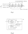
- FIG.1 is a conceptual diagram of a variable-bandwidth network according to this invention.
- FIG.2 is a block diagram of the essential parts of a source-side subscriber switch.
- FIG.3 is a conceptual diagram of an RM cell.
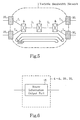
- FIG.4 is a block diagram of the essential parts of a transit switch and a destination-side subscriber switch.
- FIG.5 shows how RM cells move through the network in a first embodiment of this invention.
- FIG.6 is a block diagram of the essential parts of a transit switch and a destination-side subscriber switch in a second embodiment of this invention.
- FIG.7 shows how RM cells move through the network in a second embodiment of this invention.
- FIG.8 is a block diagram of the essential parts of a centralised controller.
- FIG.9 shows the overall configuration of, and transfer of RM cells in, a third embodiment of this invention.
- FIG.10 shows a cell output situation in a fourth embodiment of this invention.
- FIG.11 shows the flow of RM cells in a Fast Resource Management (FRM) protocol.
- FRM Fast Resource Management
- FIG.12 shows bandwidth change in an FRM protocol.
- FIG.13 shows the flow of RM cells in an ABR protocol.
- FIG.14 shows bandwidth change in an ABR protocol.
- FIG.15 shows the overall configuration of a variable-bandwidth network according to a fifth embodiment of this invention.
- FIG.16 shows an operation timing chart according to this fifth embodiment of the invention.
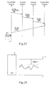
- FIG.17 shows the residual bandwidth checking sequence in the normal state in which there is no bandwidth change request.
- FIG.18 shows how a transit switch obtains the residual bandwidth of a transmission link.
- FIG.19 shows the overall configuration of a variable-bandwidth network according to a sixth embodiment of this invention.
- FIG.20 shows the control flow of the bandwidth controller in a subscriber switch.
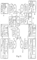
- FIG.21 shows the overall configuration of a variable-bandwidth network according to a seventh embodiment of this invention.
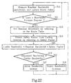
- FIG.22 shows the control flow of the bandwidth controller in a subscriber switch.
- FIG.23 shows the relation between window size and allowable bandwidth.
- FIG.24 shows the overall configuration of a variable-bandwidth network according to an eighth embodiment of this invention.
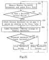
- FIG.25 is a flowchart showing the control flow of the bandwidth controller in a subscriber switch.
- FIG.26 shows the overall configuration of a variable-bandwidth network according to a ninth embodiment of this invention.
- FIG.27 is a flowchart showing the control flow of the bandwidth controller in a subscriber switch.
- FIG.28 shows the overall configuration of a variable-bandwidth network according to a tenth embodiment of this invention.
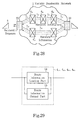
- FIG.29 is a block diagram of a transit switch and a destination-side subscriber switch according to this tenth embodiment.
- FIG.30 shows the contents of a route performance table according to the first embodiment of this invention.
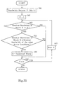
- FIG.31 is a flowchart showing the call admission procedure in the tenth embodiment of this invention.
- FIG.32 is a flowchart showing the call admission procedure according to an eleventh embodiment of this invention.
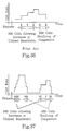
- FIG.36 shows in simplified form an example of increasing and decreasing the cell rate according to the prior art.
- a variable-bandwidth network according to this fifth embodiment comprises: transmission links 7 1 -7 3 ; transit switches 4 1 and 4 2 disposed on this transmission path; terminal 3 1 which transmits information at a cell output rate that has been set variably in accordance with the bandwidth utilisation of the transmission path; terminal 3 2 which receives this information; and subscriber switches 20 and 30 which respectively serve terminals 3 1 and 3 2 and connect them to the transmission path.
- Subscriber switch 20 has residual bandwidth table 101 which stores information relating to the bandwidth utilisation of the transmission path (in FIG.15, the table is shown external to subscriber switch 20).
- Residual bandwidth table 101 stores and manages, for each VCI, the switch buffer to which that connection belongs, and the residual bandwidth of the transmission path.
- the first step of the process of deciding for or against a bandwidth change is to obtain the safety factor from the calling interval by referring to safety factor table 80.
- the usable bandwidth is obtained by multiplying the residual bandwidth of route a by the safety factor obtained in the first step.
- the third step if the requested bandwidth is less than or equal to the usable bandwidth obtained in step 2, the request is allowed. Otherwise, the request is rejected.
- switch 41 or any other switch becomes a subscriber switch and performs bandwidth changes.
- bandwidth controller 50 of switch 40 compares the requested bandwidth with the moving average of the residual bandwidths of that route for the past N periods, as entered in route table 60. If the requested bandwidth is the smaller, then the request is accepted, but if the requested bandwidth is not smaller, the request is rejected. The same steps are performed when switch 41 or any other switch becomes a subscriber switch and performs bandwidth changes.
- switch 40 applies a first-order filter to the residual bandwidth of route a and takes the result as the residual bandwidth of the next updating period.
- the requested bandwidth is compared with the filtered residual bandwidth that has been entered in route table 60. If the requested bandwidth is the smaller, then this request is accepted, but if the requested bandwidth is not smaller, the request is rejected. The same steps are performed when switch 41 or any other switch becomes a subscriber switch and performs a bandwidth change.
- FIG.27 is a flowchart showing the control flow of a bandwidth controller in a subscriber switch.
- the residual bandwidth is measured periodically (S31).
- the smoothing coefficient ⁇ of the route table is referred to (S32).
- subscriber switch 20 comprises: route information collector 22 as means for collecting and recording, irrespective of whether there is a connection request, new route information that includes the hop number (the number of transit switch stages), the current utilised bandwidth, and the residual bandwidth of the plurality of routes set between source-side subscriber switch 20 and another subscriber switch 30 which constitutes the destination-side subscriber switch; and protocol controller 21 as means which, when there is a connection request, selects a route for the user on the basis of this recorded route information (the configuration of subscriber switch 20 is the same as that shown in FIG.2).
- route K If the residual bandwidth of route K is equal to or greater than the requested bandwidth V Mb/s, it is decided whether or not it satisfies the following relation (S54): If route K does not satisfy the above relation and the value of K does not exceed n (S56), the next route is examined (S57). If route K does satisfy Eq.2, route K is taken as the appointed route (S55).
- Centralised controller 6 shown in FIG.8 has route information collector 60 which collects information from transit switches 4 1 -4 3 and subscriber switches 30 1 and 30 2 . It collects the route information by receiving RM cells from transit switches 4 1 -4 3 and subscriber switches 30 1 and 30 2 . The route information obtained is written by route information notification part 61 to message field M of RM cells over the existing route information, and said RM cells are then transferred to source-side subscriber switches 20 1 and 20 2 .
- a source-side subscriber switch can become aware of a congestion situation and can perform suitable route selection if, when congestion has occurred in a route pertaining to its destination-side subscriber switch or to one of its transit switches, said destination-side subscriber switch or transit switch outputs, to each route, cells bearing route information that includes information relating to that congestion.
- This fourteenth embodiment of the invention comprises: transmission links 7 1 -7 3 which constitute the transmission path that performs the ATM information transfer; transit switches 4 1 and 4 2 disposed on this transmission path; terminal 3 1 which transmits information at a cell output rate that has been set variably in accordance with the bandwidth utilisation of the transmission path; terminal 3 2 which receives said information; and subscriber switches 20 and 30 which respectively serve terminals 3 1 and 3 2 and connect them to the transmission path.
- Subscriber switch 20 has residual bandwidth table 101 (in FIG.15, this is shown outside subscriber switch 20) and in this table it stores information relating to the bandwidth utilisation of the transmission path, said information being continually obtained by said subscriber switch. Subscriber switch 20 can also use RM cells to notify terminal 3 1 which it serves of congestion information.
- terminal 3 1 outputs RM cells periodically in accordance with the same procedure as in the prior art, and subscriber switch 20 compares these RM cells with residual bandwidth table 101 and returns the RM cells after having rewritten their CI bit and ER field. As a result, the bandwidth utilised by terminal 3 1 is controlled.
- FIG.38 shows the overall configuration of a variable-bandwidth network according to this fifteenth embodiment.
- FIG.39 is a block diagram of the essential parts of a source-side switch.
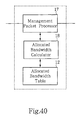
- FIG.40 is a block diagram of the essential parts of a destination-side or transit switch.
- allocated bandwidth calculator 18 comprises: means for calculating the allocatable bandwidth by referring to the aforesaid table when there has been a setup request for a requested bandwidth (Ri) on a route (the i th route) pertaining to the switch in question, or on a partial path comprising a VP on that route; means for reserving the result of this calculation in said table; and means which sets this reserved value as the new allocated bandwidth of the route in question (the i th route) or of the partial path comprising a VP on that route.
- FIG.38 shows the overall configuration of an ATM network according to this fifteenth embodiment of the invention.
- each of switches 1-1, 1-2 and 1-4 is a source-side switch
- switch 1-3 is a destination-side switch.
- Switch 1-2 can function as both a source-side switch and a destination-side switch.
- each of switches 1-1, 1-2 and 1-4 comprises: management packet transceiver 16 as means for outputting management packet 4-1 preloaded with the aforesaid requested bandwidth (R) to the VP which it is desired to set up, said management packet 4-1 being output prior to use of that VP, said management packet transceiver 16 also serving as means for recovering this management packet 4-1 after it has passed through the VP which it is desired to set up; plus route information collector 22 as means for recognising from that recovered management packet 4-1 the new allocated bandwidth for the VP which it is desired to set up.
- R requested bandwidth
- switch 1-1 receives a request for bandwidth allocation for the purpose of calling switch 1-3 via VP 2-1 and VP 2-2.
- Source-side switch 1-1 employs management packet transceiver 16 to generate, at regular intervals, management packets 4-1, writes the requested bandwidth in these packets, and transmits them to destination-side switch 1-3.
- Switch 1-2 stores and manages the unallocated bandwidth of VP 2-2 and the bandwidth allocated to switches 1-1 and 1-4.
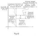
- FIG.42 shows the numerical relations which switch 1-2 uses to determine the allocated bandwidth which it notifies to switch 1-1 when it has received management packet 4-1.
- switch 1-2 when switch 1-2 receives management packet 4-1, it takes the unallocated bandwidth of VP 2-2 as the allowable bandwidth and calculates the difference between the requested bandwidth and the bandwidth currently allocated to switch 1-1. If this difference is less than the unallocated bandwidth, it sets the allocated bandwidth to the value of the requested bandwidth. However, if the difference is not less than the unallocated bandwidth, switch 1-2 takes a value which is less than the current unallocated bandwidth as the allocated bandwidth, writes this to the management packet and transmits this packet back to switch 1-1.
- switch 1-1 After switch 1-1 has received returned management packet 4-2, it obtains new allocated bandwidth information from the allocated bandwidth written in this management packet 4-2.
- Source-side switches 1-1 and 1-4 can obtain information relating to the allocated bandwidth on various routes by performing similar operations in sequence on other switches.
- each switch 1-1 to 1-4 calculates allocated bandwidths and can notify source-side switch 1-1 of the allocated bandwidth for each route. Sending and receiving of management packets is carried out periodically, or every time there is a call.
- Each switch 1-1 to 1-4 stores and manages the unallocated bandwidth of its output paths and the allocated bandwidth of each route it serves.
- switch 1-2 takes the unallocated bandwidth of output path VP 2-2 as the allowable bandwidth, reads the requested bandwidth from the received management packet 4-1, calculates the difference between the requested bandwidth and the bandwidth currently allocated to the route, and if this difference is less than the unallocated bandwidth, sets the allocated bandwidth to the value of the requested bandwidth. However, if the difference is not less than the unallocated bandwidth, switch 1-2 takes a value which is less than the current unallocated bandwidth as the allocated bandwidth, rewrites the requested bandwidth in management packet 4-1 as the value of the allocated bandwidth, and transfers the management packet to switch 1-3.
- FIG.45 is a flowchart showing the bandwidth allocation procedure in this seventeenth embodiment.
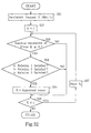
- FIG.45 assumes the same network configuration as in the fifteenth or sixteenth embodiments, and shows how the allocated bandwidth is calculated at each switch when a management packet is received. Namely, each switch holds information relating to the bandwidth of its output VP (P out ) (S77) and information relating to the total allocated bandwidth (i.e. the sum total of the allocated bandwidths Bi) of its output VP, and calculates the unallocated bandwidth of its output path (P res ) from this information (S78). Next, it calculates the sum of the unallocated bandwidth (P res ) and the bandwidth allocated to the input VP on which there was a request (Bj), and updates (Rj) to whichever of Rj or this sum is the smaller (S72).
- any switch 1-1 to 1-4 When any switch 1-1 to 1-4 receives a management packet 4-1, it reads the requested bandwidth (S71) and sets the requested bandwidth (Rj) on the basis of the input VP (j) on which there has been a request (S72).
- P out is the total bandwidth of the output VP
- ⁇ j is a parameter for adjusting the size of the increase or decrease
- ⁇ is a function of P out and the bandwidth already allocated.
- the switch updates Bj to whichever of Bj or Rj is the smaller (S74).
- any switch 1-1 to 1-4 calculates the allocated bandwidth
- the proportion of allocated bandwidth to requested bandwidth for each route is averaged and the allocation is carried out dynamically and in real time so as to satisfy, as far as possible, the requested bandwidth which was written in the management packet, provided that the allowable bandwidth is not exceeded.
- the source-side subscriber switches and the destination-side subscriber switches have been discussed as if they had different configurations. In practice, however, a single type of switch combining the configurations of both a source-side subscriber switch and a destination-side subscriber switch can be configured. Alternatively, a single type of switch combining the respective configurations of a source-side subscriber switch, a destination-side subscriber switch and a transit switch, can be configured.
Landscapes
- Engineering & Computer Science (AREA)
- Computer Networks & Wireless Communication (AREA)
- Signal Processing (AREA)
- Data Exchanges In Wide-Area Networks (AREA)
Applications Claiming Priority (13)
| Application Number | Priority Date | Filing Date | Title |
|---|---|---|---|
| JP167616/95 | 1995-07-03 | ||
| JP167585/95 | 1995-07-03 | ||
| JP16758595A JPH0918514A (ja) | 1995-07-03 | 1995-07-03 | 可変帯域通信装置 |
| JP16761695A JP3085515B2 (ja) | 1995-07-03 | 1995-07-03 | 帯域可変通信装置 |
| JP185930/95 | 1995-07-21 | ||
| JP18593095A JP3053356B2 (ja) | 1995-07-21 | 1995-07-21 | 帯域可変通信装置 |
| JP189459/95 | 1995-07-25 | ||
| JP18945995A JP3327315B2 (ja) | 1995-07-25 | 1995-07-25 | Atm通信網 |
| JP28089395A JP3327446B2 (ja) | 1995-10-27 | 1995-10-27 | Atm通信網 |
| JP280893/95 | 1995-10-27 | ||
| JP302882/95 | 1995-11-21 | ||
| JP30288295A JP3114962B2 (ja) | 1995-11-21 | 1995-11-21 | Atm通信網 |
| PCT/JP1996/001826 WO1997002685A1 (en) | 1995-07-03 | 1996-07-02 | Variable band communication network |
Publications (2)
| Publication Number | Publication Date |
|---|---|
| EP0785652A1 true EP0785652A1 (de) | 1997-07-23 |
| EP0785652A4 EP0785652A4 (de) | 2001-07-11 |
Family
ID=27553334
Family Applications (1)
| Application Number | Title | Priority Date | Filing Date |
|---|---|---|---|
| EP96921140A Withdrawn EP0785652A4 (de) | 1995-07-03 | 1996-07-02 | Kommunikationsnetzwerk mit variabler breite |
Country Status (3)
| Country | Link |
|---|---|
| US (1) | US5878029A (de) |
| EP (1) | EP0785652A4 (de) |
| WO (1) | WO1997002685A1 (de) |
Cited By (4)
| Publication number | Priority date | Publication date | Assignee | Title |
|---|---|---|---|---|
| WO1999012379A1 (en) * | 1997-08-28 | 1999-03-11 | British Telecommunications Public Limited Company | Connection admission control for connection oriented networks |
| EP0866633A3 (de) * | 1997-03-17 | 1999-07-28 | Fujitsu Limited | ATM-Vermittlungseinrichtung und ATM-Kommunikationsnetz |
| EP1300995A3 (de) * | 2001-10-05 | 2004-01-07 | Nortel Networks Limited | Ressourcenverwaltung in heterogenen dienstqualitätsbasierten Paketnetzwerken |
| CN106772091A (zh) * | 2016-12-30 | 2017-05-31 | 广东欧珀移动通信有限公司 | 电池容量值的更新方法、装置及终端 |
Families Citing this family (79)
| Publication number | Priority date | Publication date | Assignee | Title |
|---|---|---|---|---|
| US6314103B1 (en) * | 1994-05-05 | 2001-11-06 | Sprint Communications Company, L.P. | System and method for allocating bandwidth for a call |
| US6181703B1 (en) | 1995-09-08 | 2001-01-30 | Sprint Communications Company L. P. | System for managing telecommunications |
| JP3000913B2 (ja) * | 1996-02-02 | 2000-01-17 | 富士ゼロックス株式会社 | デ−タ伝送装置および方法 |
| US6961341B1 (en) * | 1996-07-02 | 2005-11-01 | Microsoft Corporation | Adaptive bandwidth throttling for network services |
| US7274662B1 (en) * | 1998-08-04 | 2007-09-25 | At&T Corp. | Method for performing segmented resource reservation |
| JP3765512B2 (ja) * | 1997-03-17 | 2006-04-12 | 富士通株式会社 | 固定長セル伝送装置並びに固定長セル送信装置及び固定長セル受信装置 |
| JPH10308745A (ja) * | 1997-05-08 | 1998-11-17 | Nec Corp | Atm網における帯域管理方法、加入者交換機及び中継交換機 |
| GB2331659A (en) * | 1997-11-21 | 1999-05-26 | Ericsson Telefon Ab L M | Resource reservation |
| US6574222B1 (en) | 1998-02-20 | 2003-06-03 | Sprint Communications Company, L.P. | System and method for allocating bandwidth for a call |
| US7079534B1 (en) | 1998-02-20 | 2006-07-18 | Sprint Communications Company L.P. | System and method for allocating bandwidth for a call |
| US6922409B1 (en) | 1998-02-20 | 2005-07-26 | Sprint Communications Company L.P. | System and method for allocating bandwidth for a call |
| US6434114B1 (en) * | 1998-02-26 | 2002-08-13 | At&T Corp | Enhancing the intelligent service capability of a network after a data flow has been established |
| US6731680B1 (en) * | 1998-05-06 | 2004-05-04 | Siemens Aktiengesellschaft | Method of changing from a first transmission path and/or transmission mode to a second transmission path and/or transmission mode |
| JP2002516525A (ja) * | 1998-05-15 | 2002-06-04 | アセンド コミュニケーションズ インコーポレイテッド | Atmネットワークにおけるフロー制御用の明示レートマーキング |
| EP0966125B1 (de) * | 1998-06-15 | 2007-04-04 | Motorola, Inc. | Verfahren und Gerät zur Verbesserung der Kapazität in einem Funkkommunikationssystem |
| DE19827347A1 (de) * | 1998-06-19 | 1999-12-23 | Alcatel Sa | Verfahren zum Anbieten und Bereithalten von Netzkapazität sowie Netzmanagementeinrichtung zur Durchführung des Verfahrens |
| JP3634635B2 (ja) * | 1998-07-31 | 2005-03-30 | 富士通株式会社 | 固定レートコネクションを制御するセル交換装置 |
| US6307838B1 (en) * | 1998-12-03 | 2001-10-23 | Siemens Aktiengesellschaft | Method for determining the required load capacity for a number of communication connections which can be statistically multiplexed |
| US7012892B1 (en) * | 1999-04-16 | 2006-03-14 | Alcatel Canada Inc. | Method and apparatus for supporting connection type partitioning in a communications network |
| US7103068B1 (en) | 1999-05-04 | 2006-09-05 | Sprint Communication Company L.P. | System and method for configuring bandwidth transmission rates for call connections |
| US6625155B1 (en) | 1999-09-28 | 2003-09-23 | Lucent Technologies Inc. | Model-based admission control adjustment in data networks |
| US6791941B1 (en) | 1999-09-28 | 2004-09-14 | Lucent Technologies Inc. | Learning-based admission control adjustment in data networks |
| US6697369B1 (en) | 1999-09-28 | 2004-02-24 | Lucent Technologies Inc | Admission control adjustment in data networks using maximum cell count |
| US6785377B1 (en) | 2000-01-19 | 2004-08-31 | Sprint Communications Company L.P. | Data calls using both constant bit rate and variable bit rate connections |
| JP2001237855A (ja) * | 2000-02-25 | 2001-08-31 | Fujitsu Ltd | 交換システムおよびそのルーティング方法 |
| US7149795B2 (en) * | 2000-09-18 | 2006-12-12 | Converged Access, Inc. | Distributed quality-of-service system |
| US20020194361A1 (en) * | 2000-09-22 | 2002-12-19 | Tomoaki Itoh | Data transmitting/receiving method, transmitting device, receiving device, transmiting/receiving system, and program |
| US20020131416A1 (en) * | 2001-03-19 | 2002-09-19 | Stefan Pudas | Dynamic set-up of ATM bearers for AAL2 connections |
| WO2002096029A1 (en) | 2001-05-18 | 2002-11-28 | Telstra Corporation Limited | Network bandwidth control |
| US20040042398A1 (en) * | 2002-02-28 | 2004-03-04 | Seriqa Networks | Method and apparatus for reducing traffic congestion by preventing allocation of the occupied portion of the link capacity and for protecting a switch from congestion by preventing allocation on some of its links |
| US7447206B1 (en) * | 2002-07-15 | 2008-11-04 | Cisco Technology, Inc. | PVC suited for supporting user applications with changing requirements |
| US7339896B2 (en) * | 2002-09-10 | 2008-03-04 | International Business Machines Corporation | Available bandwidth detector for SAN switch ports |
| US7327692B2 (en) * | 2002-09-10 | 2008-02-05 | International Business Machines Corporation | System and method for selecting fibre channel switched fabric frame paths |
| US20040073690A1 (en) * | 2002-09-30 | 2004-04-15 | Neil Hepworth | Voice over IP endpoint call admission |
| US7359979B2 (en) * | 2002-09-30 | 2008-04-15 | Avaya Technology Corp. | Packet prioritization and associated bandwidth and buffer management techniques for audio over IP |
| US7706282B2 (en) * | 2003-06-25 | 2010-04-27 | Leping Huang | Bluetooth personal area network routing protocol optimization using connectivity metric |
| WO2005062543A1 (ja) * | 2003-12-24 | 2005-07-07 | Nippon Telegraph And Telephone Corporation | 動的帯域割当回路、動的帯域割当方法、動的帯域割当プログラム、及び記録媒体 |
| US7978827B1 (en) | 2004-06-30 | 2011-07-12 | Avaya Inc. | Automatic configuration of call handling based on end-user needs and characteristics |
| US7768920B2 (en) * | 2005-06-29 | 2010-08-03 | Bandwb Ltd. | Means and methods for dynamically allocating bandwidth |
| US20070153763A1 (en) * | 2005-12-29 | 2007-07-05 | Rampolla Richard A | Route change monitor for communication networks |
| US8488447B2 (en) | 2006-06-30 | 2013-07-16 | Centurylink Intellectual Property Llc | System and method for adjusting code speed in a transmission path during call set-up due to reduced transmission performance |
| US8717911B2 (en) * | 2006-06-30 | 2014-05-06 | Centurylink Intellectual Property Llc | System and method for collecting network performance information |
| US8477614B2 (en) | 2006-06-30 | 2013-07-02 | Centurylink Intellectual Property Llc | System and method for routing calls if potential call paths are impaired or congested |
| US8194643B2 (en) | 2006-10-19 | 2012-06-05 | Embarq Holdings Company, Llc | System and method for monitoring the connection of an end-user to a remote network |
| US9094257B2 (en) | 2006-06-30 | 2015-07-28 | Centurylink Intellectual Property Llc | System and method for selecting a content delivery network |
| US8289965B2 (en) | 2006-10-19 | 2012-10-16 | Embarq Holdings Company, Llc | System and method for establishing a communications session with an end-user based on the state of a network connection |
| US7760641B2 (en) * | 2006-07-10 | 2010-07-20 | International Business Machines Corporation | Distributed traffic shaping across a cluster |
| US7813276B2 (en) * | 2006-07-10 | 2010-10-12 | International Business Machines Corporation | Method for distributed hierarchical admission control across a cluster |
| US8238253B2 (en) | 2006-08-22 | 2012-08-07 | Embarq Holdings Company, Llc | System and method for monitoring interlayer devices and optimizing network performance |
| US8064391B2 (en) | 2006-08-22 | 2011-11-22 | Embarq Holdings Company, Llc | System and method for monitoring and optimizing network performance to a wireless device |
| US7843831B2 (en) | 2006-08-22 | 2010-11-30 | Embarq Holdings Company Llc | System and method for routing data on a packet network |
| US20080052206A1 (en) * | 2006-08-22 | 2008-02-28 | Edwards Stephen K | System and method for billing users for communicating over a communications network |
| US8144587B2 (en) | 2006-08-22 | 2012-03-27 | Embarq Holdings Company, Llc | System and method for load balancing network resources using a connection admission control engine |
| US8015294B2 (en) | 2006-08-22 | 2011-09-06 | Embarq Holdings Company, LP | Pin-hole firewall for communicating data packets on a packet network |
| US8224255B2 (en) | 2006-08-22 | 2012-07-17 | Embarq Holdings Company, Llc | System and method for managing radio frequency windows |
| US8274905B2 (en) | 2006-08-22 | 2012-09-25 | Embarq Holdings Company, Llc | System and method for displaying a graph representative of network performance over a time period |
| US8199653B2 (en) | 2006-08-22 | 2012-06-12 | Embarq Holdings Company, Llc | System and method for communicating network performance information over a packet network |
| US8407765B2 (en) | 2006-08-22 | 2013-03-26 | Centurylink Intellectual Property Llc | System and method for restricting access to network performance information tables |
| US8537695B2 (en) | 2006-08-22 | 2013-09-17 | Centurylink Intellectual Property Llc | System and method for establishing a call being received by a trunk on a packet network |
| US9479341B2 (en) | 2006-08-22 | 2016-10-25 | Centurylink Intellectual Property Llc | System and method for initiating diagnostics on a packet network node |
| US8750158B2 (en) | 2006-08-22 | 2014-06-10 | Centurylink Intellectual Property Llc | System and method for differentiated billing |
| US8576722B2 (en) | 2006-08-22 | 2013-11-05 | Centurylink Intellectual Property Llc | System and method for modifying connectivity fault management packets |
| US8619600B2 (en) | 2006-08-22 | 2013-12-31 | Centurylink Intellectual Property Llc | System and method for establishing calls over a call path having best path metrics |
| US8189468B2 (en) | 2006-10-25 | 2012-05-29 | Embarq Holdings, Company, LLC | System and method for regulating messages between networks |
| US8743703B2 (en) | 2006-08-22 | 2014-06-03 | Centurylink Intellectual Property Llc | System and method for tracking application resource usage |
| US8531954B2 (en) * | 2006-08-22 | 2013-09-10 | Centurylink Intellectual Property Llc | System and method for handling reservation requests with a connection admission control engine |
| US8223655B2 (en) | 2006-08-22 | 2012-07-17 | Embarq Holdings Company, Llc | System and method for provisioning resources of a packet network based on collected network performance information |
| US8307065B2 (en) | 2006-08-22 | 2012-11-06 | Centurylink Intellectual Property Llc | System and method for remotely controlling network operators |
| US7684332B2 (en) | 2006-08-22 | 2010-03-23 | Embarq Holdings Company, Llc | System and method for adjusting the window size of a TCP packet through network elements |
| US8130793B2 (en) | 2006-08-22 | 2012-03-06 | Embarq Holdings Company, Llc | System and method for enabling reciprocal billing for different types of communications over a packet network |
| US8068425B2 (en) | 2008-04-09 | 2011-11-29 | Embarq Holdings Company, Llc | System and method for using network performance information to determine improved measures of path states |
| US8218751B2 (en) * | 2008-09-29 | 2012-07-10 | Avaya Inc. | Method and apparatus for identifying and eliminating the source of background noise in multi-party teleconferences |
| JP5589808B2 (ja) * | 2010-02-24 | 2014-09-17 | 富士通株式会社 | 通信装置および経路割当方法 |
| CN102143052B (zh) * | 2010-11-08 | 2013-10-09 | 华为技术有限公司 | 一种无损带宽调整方法、设备及系统 |
| US9064234B2 (en) * | 2011-07-13 | 2015-06-23 | Right Intel Corporation | Systems and methods for the analysis and dissemination of data within a networked community |
| US9071541B2 (en) | 2012-04-25 | 2015-06-30 | Juniper Networks, Inc. | Path weighted equal-cost multipath |
| US8787400B1 (en) | 2012-04-25 | 2014-07-22 | Juniper Networks, Inc. | Weighted equal-cost multipath |
| US9577925B1 (en) | 2013-07-11 | 2017-02-21 | Juniper Networks, Inc. | Automated path re-optimization |
| US11962486B2 (en) * | 2016-06-06 | 2024-04-16 | Telefonaktiebolaget Lm Ericsson (Publ) | Determining a path in a communication network |
Family Cites Families (14)
| Publication number | Priority date | Publication date | Assignee | Title |
|---|---|---|---|---|
| JPH04229747A (ja) * | 1990-08-17 | 1992-08-19 | Hitachi Ltd | パケット交換方法、およびパケット交換システム |
| JP3278865B2 (ja) * | 1991-06-28 | 2002-04-30 | 日本電気株式会社 | トラヒック制御方法 |
| JPH05183579A (ja) * | 1991-11-08 | 1993-07-23 | Mitsubishi Electric Corp | 通信経路選択装置及び通信経路選択方法及びデータ交換装置 |
| JPH05268240A (ja) * | 1992-03-18 | 1993-10-15 | Fujitsu Ltd | Atm交換網におけるルート選択方式 |
| JPH0697952A (ja) * | 1992-08-10 | 1994-04-08 | Nippon Telegr & Teleph Corp <Ntt> | 非同期転送モードプライベート網エンドカスタマ制御方式 |
| JP3672341B2 (ja) * | 1993-07-21 | 2005-07-20 | 富士通株式会社 | 通信網分離設計方式とその管理方式 |
| JP3187230B2 (ja) * | 1993-09-06 | 2001-07-11 | 株式会社東芝 | ふくそう制御方法及びふくそう制御装置 |
| JPH07221763A (ja) * | 1994-01-31 | 1995-08-18 | Nippon Telegr & Teleph Corp <Ntt> | Atm交換装置 |
| GB2288947B (en) * | 1994-04-20 | 1999-01-06 | Roke Manor Research | Improvements in or relating to ATM communication systems |
| US5515359A (en) * | 1994-08-26 | 1996-05-07 | Mitsubishi Electric Research Laboratories, Inc. | Credit enhanced proportional rate control system |
| US5633859A (en) * | 1994-09-16 | 1997-05-27 | The Ohio State University | Method and apparatus for congestion management in computer networks using explicit rate indication |
| US5649110A (en) * | 1994-11-07 | 1997-07-15 | Ben-Nun; Michael | Traffic shaping system with virtual circuit table time stamps for asynchronous transfer mode networks |
| US5675576A (en) * | 1995-06-05 | 1997-10-07 | Lucent Technologies Inc. | Concestion control system and method for packet switched networks providing max-min fairness |
| US5546377A (en) * | 1995-10-31 | 1996-08-13 | Digital Equipment Corporation | Efficient distributed method for computing max-min fair rates of a limited resource in ATM networks |
-
1996
- 1996-07-02 WO PCT/JP1996/001826 patent/WO1997002685A1/ja not_active Ceased
- 1996-07-02 EP EP96921140A patent/EP0785652A4/de not_active Withdrawn
-
1997
- 1997-02-12 US US08/799,412 patent/US5878029A/en not_active Expired - Lifetime
Cited By (7)
| Publication number | Priority date | Publication date | Assignee | Title |
|---|---|---|---|---|
| EP0866633A3 (de) * | 1997-03-17 | 1999-07-28 | Fujitsu Limited | ATM-Vermittlungseinrichtung und ATM-Kommunikationsnetz |
| US6282197B1 (en) | 1997-03-17 | 2001-08-28 | Fujitsu Limited | ATM switching apparatus and ATM communications network |
| WO1999012379A1 (en) * | 1997-08-28 | 1999-03-11 | British Telecommunications Public Limited Company | Connection admission control for connection oriented networks |
| US6665264B1 (en) * | 1997-08-28 | 2003-12-16 | British Telecommunications Public Limited Company | Connection admission control for connection orientated networks |
| EP1300995A3 (de) * | 2001-10-05 | 2004-01-07 | Nortel Networks Limited | Ressourcenverwaltung in heterogenen dienstqualitätsbasierten Paketnetzwerken |
| US7092356B2 (en) | 2001-10-05 | 2006-08-15 | Nortel Networks Limited | Resource management in heterogenous QoS-based packet Networks |
| CN106772091A (zh) * | 2016-12-30 | 2017-05-31 | 广东欧珀移动通信有限公司 | 电池容量值的更新方法、装置及终端 |
Also Published As
| Publication number | Publication date |
|---|---|
| EP0785652A4 (de) | 2001-07-11 |
| US5878029A (en) | 1999-03-02 |
| WO1997002685A1 (en) | 1997-01-23 |
Similar Documents
| Publication | Publication Date | Title |
|---|---|---|
| US5878029A (en) | Variable-bandwidth network | |
| US6442138B1 (en) | Method and apparatus for controlling admission of connection requests | |
| JP3732981B2 (ja) | 連続ビット・レート仮想パス接続の帯域幅を動的に調節するための方法 | |
| US6108304A (en) | Packet switching network, packet switching equipment, and network management equipment | |
| US6046983A (en) | Dynamic rate control system | |
| US6081505A (en) | Cell scheduling system and method for networks nodes | |
| JP3686493B2 (ja) | Atm交換機におけるフィードバック制御方法および装置 | |
| US6282197B1 (en) | ATM switching apparatus and ATM communications network | |
| US5914937A (en) | B-ISDN access | |
| JP2000324111A (ja) | Atm交換機の輻輳制御方式 | |
| US20030156583A1 (en) | System and method for parallel connection selection in a communication network | |
| EP0884923B1 (de) | Paketvermittlungsnetzwerk, Paketvermittlungseinrichtung und Netzwerkmanagementeinrichtung | |
| Burgin | Management of capacity and control in broadband ISDN | |
| US6272111B1 (en) | Routing system | |
| Gaïti et al. | Cooperative congestion control schemes in ATM networks | |
| JP3070907B2 (ja) | Atm通信網および経路変更方法 | |
| JP3763266B2 (ja) | 帯域割当方法および帯域割当装置 | |
| KR20000035007A (ko) | 네트워크 적재에 따른 연속 비트율의 가상 패스 접속의 대역폭을 동적으로 조절하기 위한 패킷 교환망에서의 방법 및 시스템 | |
| EP1337078B1 (de) | Auf Lastausgleich basierende Auswahl von Verbindungsleitungsgruppen in einem Kommunikationsnetz | |
| JPH0662035A (ja) | 通信網の経路制御方法 | |
| JP3059101B2 (ja) | Atmスイッチ | |
| JPH0918515A (ja) | 帯域可変通信装置 | |
| JP3327446B2 (ja) | Atm通信網 | |
| JP2741913B2 (ja) | Atm通信におけるルーティング制御方式 | |
| KR100265070B1 (ko) | 실시간으로 트래픽을 관리하는 비동기 전송모드의 감시정보처리유닛에서 셀 율 및 평균 셀 율 제어방법 |
Legal Events
| Date | Code | Title | Description |
|---|---|---|---|
| PUAI | Public reference made under article 153(3) epc to a published international application that has entered the european phase |
Free format text: ORIGINAL CODE: 0009012 |
|
| 17P | Request for examination filed |
Effective date: 19970221 |
|
| AK | Designated contracting states |
Kind code of ref document: A1 Designated state(s): DE FR GB |
|
| A4 | Supplementary search report drawn up and despatched |
Effective date: 20010525 |
|
| AK | Designated contracting states |
Kind code of ref document: A4 Designated state(s): DE FR GB |
|
| 17Q | First examination report despatched |
Effective date: 20070809 |
|
| STAA | Information on the status of an ep patent application or granted ep patent |
Free format text: STATUS: THE APPLICATION IS DEEMED TO BE WITHDRAWN |
|
| 18D | Application deemed to be withdrawn |
Effective date: 20140201 |
|
| REG | Reference to a national code |
Ref country code: DE Ref legal event code: R079 Free format text: PREVIOUS MAIN CLASS: H04L0012560000 Ipc: H04L0012801000 |
|
| REG | Reference to a national code |
Ref country code: DE Ref legal event code: R079 Free format text: PREVIOUS MAIN CLASS: H04L0012560000 Ipc: H04L0012801000 Effective date: 20140702 |