EP0786589B1 - Method and unit for controlling the supercharge pressure of a turbodiesel engine with a variable-geometry turbine - Google Patents
Method and unit for controlling the supercharge pressure of a turbodiesel engine with a variable-geometry turbine Download PDFInfo
- Publication number
- EP0786589B1 EP0786589B1 EP97101048A EP97101048A EP0786589B1 EP 0786589 B1 EP0786589 B1 EP 0786589B1 EP 97101048 A EP97101048 A EP 97101048A EP 97101048 A EP97101048 A EP 97101048A EP 0786589 B1 EP0786589 B1 EP 0786589B1
- Authority
- EP
- European Patent Office
- Prior art keywords
- signal
- pressure
- proportional
- generating
- psmis
- Prior art date
- Legal status (The legal status is an assumption and is not a legal conclusion. Google has not performed a legal analysis and makes no representation as to the accuracy of the status listed.)
- Expired - Lifetime
Links
- 238000000034 method Methods 0.000 title claims description 14
- 238000012937 correction Methods 0.000 claims description 20
- 230000001133 acceleration Effects 0.000 claims description 17
- 230000000977 initiatory effect Effects 0.000 claims description 7
- 230000006870 function Effects 0.000 description 6
- 230000003213 activating effect Effects 0.000 description 3
- 230000010355 oscillation Effects 0.000 description 3
- 238000010586 diagram Methods 0.000 description 2
- 230000000630 rising effect Effects 0.000 description 2
- 238000012546 transfer Methods 0.000 description 2
- 238000002485 combustion reaction Methods 0.000 description 1
- 238000013016 damping Methods 0.000 description 1
- 230000007423 decrease Effects 0.000 description 1
- 238000011161 development Methods 0.000 description 1
- 230000018109 developmental process Effects 0.000 description 1
- 238000012544 monitoring process Methods 0.000 description 1
- 230000004044 response Effects 0.000 description 1
- 238000012360 testing method Methods 0.000 description 1
Images


Classifications
-
- F—MECHANICAL ENGINEERING; LIGHTING; HEATING; WEAPONS; BLASTING
- F02—COMBUSTION ENGINES; HOT-GAS OR COMBUSTION-PRODUCT ENGINE PLANTS
- F02D—CONTROLLING COMBUSTION ENGINES
- F02D41/00—Electrical control of supply of combustible mixture or its constituents
- F02D41/0002—Controlling intake air
- F02D41/0007—Controlling intake air for control of turbo-charged or super-charged engines
-
- F—MECHANICAL ENGINEERING; LIGHTING; HEATING; WEAPONS; BLASTING
- F02—COMBUSTION ENGINES; HOT-GAS OR COMBUSTION-PRODUCT ENGINE PLANTS
- F02B—INTERNAL-COMBUSTION PISTON ENGINES; COMBUSTION ENGINES IN GENERAL
- F02B37/00—Engines characterised by provision of pumps driven at least for part of the time by exhaust
- F02B37/12—Control of the pumps
- F02B37/24—Control of the pumps by using pumps or turbines with adjustable guide vanes
-
- F—MECHANICAL ENGINEERING; LIGHTING; HEATING; WEAPONS; BLASTING
- F02—COMBUSTION ENGINES; HOT-GAS OR COMBUSTION-PRODUCT ENGINE PLANTS
- F02D—CONTROLLING COMBUSTION ENGINES
- F02D41/00—Electrical control of supply of combustible mixture or its constituents
- F02D41/02—Circuit arrangements for generating control signals
- F02D41/14—Introducing closed-loop corrections
- F02D41/1401—Introducing closed-loop corrections characterised by the control or regulation method
- F02D2041/1409—Introducing closed-loop corrections characterised by the control or regulation method using at least a proportional, integral or derivative controller
-
- Y—GENERAL TAGGING OF NEW TECHNOLOGICAL DEVELOPMENTS; GENERAL TAGGING OF CROSS-SECTIONAL TECHNOLOGIES SPANNING OVER SEVERAL SECTIONS OF THE IPC; TECHNICAL SUBJECTS COVERED BY FORMER USPC CROSS-REFERENCE ART COLLECTIONS [XRACs] AND DIGESTS
- Y02—TECHNOLOGIES OR APPLICATIONS FOR MITIGATION OR ADAPTATION AGAINST CLIMATE CHANGE
- Y02T—CLIMATE CHANGE MITIGATION TECHNOLOGIES RELATED TO TRANSPORTATION
- Y02T10/00—Road transport of goods or passengers
- Y02T10/10—Internal combustion engine [ICE] based vehicles
- Y02T10/12—Improving ICE efficiencies
Definitions
- the present invention relates to a method and unit for controlling the supercharge pressure of a turbodiesel engine with a variable-geometry turbine.
- turbodiesel engines equipped with a variable-geometry turbine provide for more power as compared with traditional types.
- Such turbines permit more rapid response and increased torque at low engine speed, and greater power at high engine speed.
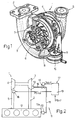
- Number 1 in Figure 1 indicates a turbosupercharger comprising a spiral-shaped inlet conduit 2 for the exhaust gas produced by combustion in an engine (not shown); a turbine 3 activated by the exhaust gas; a first outlet conduit (not shown) for expelling the exhaust gas after activating the turbine; a second inlet conduit (not shown) for the intake of air; an air compressor 4 activated by turbine 3; and a second outlet conduit 5 for supplying the compressed air to the engine.
- Turbine 3 comprises a bladed rotor 6, and a variable-geometry blade system 7 comprising a number of blades 8 located between first inlet conduit 2 and bladed rotor 6.
- Blades 8 are adjustable, and are activated by a control assembly 9 comprising a diaphragm actuating member 10 and an actuating assembly (not shown in Figure 1) for activating actuating member 10 and described in detail later on with reference to Figure 2.
- a control assembly 9 comprising a diaphragm actuating member 10 and an actuating assembly (not shown in Figure 1) for activating actuating member 10 and described in detail later on with reference to Figure 2.
- blades 8 vary the section of the exhaust gas passage as a function of the output pressure of compressor 4, regulate the speed of the exhaust gas, and continuously control the supercharge pressure.
- blades 8 depends on the operating conditions of the engine. More specifically, at low engine speed and under low load conditions, blades 8 are set to the fully closed position to reduce the section of the gas passage and increase the speed of the gas in turbine 3.
- the actuating assembly - indicated by 11 - for activating actuating member 10 comprises a vacuum pump 12 activated by the engine - indicated by 13 - to which turbosupercharger 1 is fitted; and a known vacuum-modulating three-way solenoid valve 14 connected to vacuum pump 12 by an input line 15.
- vacuum pump 12 is driven by the camshaft 13a or the drive shaft (not shown) of engine 13.
- Solenoid valve 14 is connected to actuating member 10 by an output line 16, and is controlled by a control unit 17.
- Control unit 17 comprises a pressure sensor 18 and an electronic central control unit 19.
- Pressure sensor 18 is located along second outlet conduit 5 of turbosupercharger 1, and generates a pressure signal PSmis proportional to the supercharge pressure in second outlet conduit 5 of supercharger 1.
- Electronic central control unit 19 receives pressure signal PSmis and a reference signal PSrif proportional to a desired supercharge pressure value and mapped in a memory (not shown), and generates a control signal DutyV related to the optimum opening angle of blades 8 in Figure 1.
- Control signal DutyV is supplied to actuating assembly 11 of actuating member 10, and more specifically to solenoid valve 14.
- vacuum pump 12 In actual use, vacuum pump 12 generates a vacuum, which is supplied to and modulated by solenoid valve 14 according to the value of control signal DutyV, so as to control the diaphragm of actuator 10 in known manner (not shown) and so adjust the position of blades 8 in Figure 1.
- control signal DutyV of solenoid valve 14 is generated by a known proportional-integral control - not described in detail - which performs a transfer function having, for the proportional and integral part respectively, two multiplication coefficients Kp and Ki, which assume a fixed value regardless of the operating point of the engine.
- Proportional-integral control is poorly suited to controlling the power output of a turbodiesel engine with a variable-geometry turbine during acceleration, in that it is slow and acts on blades 8 ( Figure 1) with a delay which is incompatible with the sudden increase in power of the engine at the acceleration stage.
- the delay referred to is manifested by the supercharge pressure overshooting the desired value, and subsequently settling at the desired value accompanied by oscillations with a small damping coefficient.
- a method of controlling the supercharge pressure of a turbodiesel engine comprising a turbosupercharger with a variable-geometry turbine having blades movable between two limit positions, and a control assembly for controlling said blades and driven by a control signal; characterized by comprising the steps of:
- the present invention also relates to a control unit for controlling the supercharge pressure of a turbodiesel engine comprising a turbosupercharger with a variable-geometry turbine having blades movable between two limit positions, and a control assembly for controlling said blades and driven by a control signal; said control unit comprising pressure sensing means generating a pressure signal proportional to the supercharge pressure in said engine; characterized by comprising deriving means for generating a correction signal proportional to a derivative of said pressure signal; and combining means for effecting a linear combination of said pressure signal, said correction signal and said reference signal, and for generating an acceleration output signal constituting said control signal, said acceleration output signal using said linear combination and no integral pressure control term when said correction signal is used for determining said control signal.
- control unit receives reference signal PSrif and pressure signal PSmis, and generates control signal DutyV of solenoid valve 14.
- Control unit 20 comprises a mixed proportional-derivative control group (hereinafter abbreviated mixed PD control group) 21, and a proportional-integral control group (hereinafter abbreviated PI control group) 22, which selectively control solenoid valve 14 in Figure 1 according to the operating state of the engine.
- mixed PD control group a mixed proportional-derivative control group
- PI control group a proportional-integral control group
- Mixed PD control group 21 comprises a proportional branch 23 and a derivative branch 24.
- Proportional branch 23 comprises a first adding block 25 receiving pressure and reference signals PSmis and PSrif, and generating a first error signal Err equal to the difference PSrif-PSmis; and a first multiplying block 26 receiving error signal Err, and generating a proportional signal U 1 equal to first error signal Err multiplied by a first constant Kp 1 .
- Derivative branch 24 comprises a deriving block 27 receiving pressure signal PSmis, and generating a first correction signal DPS equal to the time derivative of pressure signal PSmis; and a second multiplying block 28 receiving first correction signal DPS, and generating a derivative signal U 2 equal to first correction signal DPS multiplied by a second constant Kd.
- Initiating signal U 3 is a constant-value signal for defining a reference position of blades 8 in Figure 1 in the absence of proportional and derivative signals U 1 , U 2 .
- PI control group 22 comprises a third adding block 30 receiving pressure and reference signals PSmis and PSrif, and generating a second error signal Err equal to PSrif-PSmis; and a proportional-integral control block 31 receiving second error signal Err, and generating a proportional-integral output signal DutyV2.
- Control block 31 performs a transfer function having, for the proportional and integral part respectively, two multiplication coefficients Kp 2 and Ki, the value of which depends on the operating point of the engine, and is mapped in a memory (not shown).
- the value of multiplication coefficient Kp 2 is determined using a pseudo-random method; and the value of multiplication coefficient Ki is related to that of Kp 2 by a constant which takes into account the gain and cutoff frequency of control block 31.
- PD and PI control groups 21 and 22 are enabled alternately by a selection device 32 receiving pressure signal PSmis, and which, on the basis of pressure signal PSmis, generates an enabling signal S, the value of which determines operation of PD control group 21 or PI control group 22.
- the control signal DutyV generated by control unit 20 equals acceleration output signal DutyV1 or proportional-integral output signal DutyV2, depending on which control group 21 or 22 is enabled.
- selection device 32 enables PI control group 22 (block 35), so that, at this phase, control signal DutyV equals proportional-integral output signal DutyV2 and control is proportional-integral.
- turbosupercharger 1 During operation of turbosupercharger 1, the supercharge pressure of the engine is monitored continually by calculating a time derivative of pressure signal PSmis (block 36).
- control signal DutyV equals acceleration output signal DutyV1 and control is proportional-derivative.
- selection device 32 continues monitoring the supercharge pressure derivative and the time t elapsed since the threshold was crossed (block 39), to determine whether the supercharge pressure has reached the supercharge peak, or whether, following crossover of the threshold, the rate of increase in supercharge pressure has fallen to such a value that it would take too long for the desired value (proportional to PSrif) to be reached.
- proportional branch 23 when the supercharge pressure increases sharply and PD control group 21 is enabled, proportional branch 23 generates proportional signal U 1 , which increases or decreases the value of initiating signal U 3 by a quantity proportional to the difference between pressure signal PSmis and reference signal PSrif.
- derivative branch 24 determines a first correction signal DPS equal to the time derivative of pressure signal PSmis, and generates a derivative signal U 2 , which contributes towards reducing control signal DutyV, here equal to acceleration output signal DutyV1.
- Derivative branch 24 therefore provides for reducing the value of control signal DutyV as of the instant in which the supercharge pressure derivative exceeds the predetermined threshold, i.e. in advance of the instant in which the desired pressure value is reached.
- control signal DutyV The reason for this advanced correction of control signal DutyV is that, despite proportional signal U 1 generated by proportional branch 23 eliminating its contribution to control signal DutyV when the desired supercharge pressure value is reached, the supercharge pressure continues rising on account of the large amount of residual energy contained in the exhaust gas.
- deriving block 27 of mixed PD control group 21 operates directly on pressure signal PSmis proportional to the measured supercharge pressure, as opposed to first error signal Err proportional to the pressure error.
- deriving block 27 represents the most suitable performance estimator for faithfully modelling the increase in supercharge pressure of turbodiesel engines with a variable-geometry turbine, and is therefore the best type of control for generating derivative signal U 2 used for advanced correction of control signal DutyV.
- a return to proportional-integral control requires that the initial state of the integrator in the integral block be supplied, i.e. that PI control group 22 be supplied with an integral contribution value I plausible with previous control developments. More specifically, the contribution value is determined as a function of engine speed and load, and is memorized in an appropriate vector.
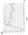
- Figure 5 shows a number of time curves relative to dynamic bench tests conducted on a turbodiesel engine with a variable-geometry turbine during acceleration and in second gear as of 2000 revolutions per minute.
- Figure 5 graph shows the supercharge pressure curve P 1 relative to the method according to the present invention (continuous line); the supercharge pressure curve P 2 relative to straightforward proportional-integral control (dash line); and the reference supercharge pressure curve P rif (dotted line).
- the method according to the invention provides for considerably reducing the supercharge pressure overshoot peak, and for following the reference pressure curve fairly closely with only low-amplitude oscillation.
- the advantages of the present method are as follows.
- it provides for better controlling the output power of the engine by reducing both the duration and amplitude of the oscillations involved in reaching the desired supercharge pressure value, thus greatly reducing the time taken by the engine to reach the optimum running condition.
- the supercharge pressure overshoot peak is controllable by working on constants Kp 1 and Kd.
- proportional-integral control during the steady-state phase provides, in known manner, for controlling variations in the reference signal with a zero tracking error in the absence of rapid increases in pressure.
Landscapes
- Engineering & Computer Science (AREA)
- Chemical & Material Sciences (AREA)
- Combustion & Propulsion (AREA)
- Mechanical Engineering (AREA)
- General Engineering & Computer Science (AREA)
- Supercharger (AREA)
- Control Of Turbines (AREA)
Applications Claiming Priority (2)
| Application Number | Priority Date | Filing Date | Title |
|---|---|---|---|
| ITTO960047 | 1996-01-26 | ||
| IT96TO000047A IT1284345B1 (it) | 1996-01-26 | 1996-01-26 | Metodo e unita' di controllo della pressione di sovralimentazione per un motore turbodiesel con turbina a geometria variabile |
Publications (2)
| Publication Number | Publication Date |
|---|---|
| EP0786589A1 EP0786589A1 (en) | 1997-07-30 |
| EP0786589B1 true EP0786589B1 (en) | 2001-11-14 |
Family
ID=11414163
Family Applications (1)
| Application Number | Title | Priority Date | Filing Date |
|---|---|---|---|
| EP97101048A Expired - Lifetime EP0786589B1 (en) | 1996-01-26 | 1997-01-23 | Method and unit for controlling the supercharge pressure of a turbodiesel engine with a variable-geometry turbine |
Country Status (5)
| Country | Link |
|---|---|
| US (1) | US5867986A (it) |
| EP (1) | EP0786589B1 (it) |
| DE (1) | DE69708166T2 (it) |
| ES (1) | ES2167624T3 (it) |
| IT (1) | IT1284345B1 (it) |
Families Citing this family (31)
| Publication number | Priority date | Publication date | Assignee | Title |
|---|---|---|---|---|
| DE19712861A1 (de) * | 1997-03-27 | 1998-10-01 | Bosch Gmbh Robert | Verfahren zum Regeln der Aufladung einer Brennkraftmaschine |
| US6000221A (en) * | 1997-11-04 | 1999-12-14 | Detroit Diesel Corporation | System for controlling a variable geometry turbocharger |
| DE19750445C1 (de) * | 1997-11-14 | 1999-06-24 | Daimler Chrysler Ag | Verfahren zur Steuerung eines VTG-Abgasturboladers |
| DE19751977C2 (de) * | 1997-11-25 | 2001-02-01 | Daimler Chrysler Ag | Steuerung für den Ladedruck einer aufgeladenen Brennkraftmaschine |
| DE19830575A1 (de) * | 1998-07-08 | 2000-01-13 | Nonox B V | Ladungssteuervorrichtung für eine sowie Verfahren zum Steuern des Betriebs einer Hubkolbenbrennkraftmaschine |
| DE19844213C1 (de) * | 1998-09-26 | 1999-05-27 | Daimler Chrysler Ag | Verfahren zur Regelung oder Steuerung einer aufgeladenen Brennkraftmaschine |
| US6178749B1 (en) | 1999-01-26 | 2001-01-30 | Ford Motor Company | Method of reducing turbo lag in diesel engines having exhaust gas recirculation |
| US6035639A (en) * | 1999-01-26 | 2000-03-14 | Ford Global Technologies, Inc. | Method of estimating mass airflow in turbocharged engines having exhaust gas recirculation |
| US6067800A (en) * | 1999-01-26 | 2000-05-30 | Ford Global Technologies, Inc. | Control method for a variable geometry turbocharger in a diesel engine having exhaust gas recirculation |
| US6035640A (en) * | 1999-01-26 | 2000-03-14 | Ford Global Technologies, Inc. | Control method for turbocharged diesel engines having exhaust gas recirculation |
| DE19905420A1 (de) * | 1999-02-10 | 2000-08-17 | Bayerische Motoren Werke Ag | Ladedruck-Regelverfahren für einen Abgasturbolader |
| FR2790036B1 (fr) | 1999-02-23 | 2001-05-18 | Renault | Procede de commande d'un turbocompresseur a geometrie variable, notamment pour moteur diesel |
| DE19960166A1 (de) * | 1999-12-14 | 2001-06-21 | Fev Motorentech Gmbh | Verfahren zur Regelung des Ladedrucks an einer Kolbenbrennkraftmaschine mit Turbolader |
| US6418719B2 (en) | 2000-01-25 | 2002-07-16 | International Engine Intellectual Property Company, L.L.C. | Control of a variable geometry turbocharger by sensing exhaust pressure |
| US6427445B1 (en) | 2000-02-10 | 2002-08-06 | International Engine Intellectual Property Company, L.L.C. | Variable nozzle turbine control strategy |
| DE10062350A1 (de) * | 2000-12-14 | 2002-06-20 | Daimler Chrysler Ag | Verfahren zur Regelung einer Aufladeeinrichtung für einen Verbrennungsmotor |
| ITTO20010041A1 (it) * | 2001-01-19 | 2002-07-19 | Iveco Motorenforschung Ag | Sistema di controllo per turbocompressore a geometria variabile. |
| US6729026B2 (en) * | 2001-02-13 | 2004-05-04 | Medallion Technology, Llc | Rotational grip twist machine and method for fabricating bulges of twisted wire electrical connectors |
| JP3873742B2 (ja) * | 2001-12-28 | 2007-01-24 | いすゞ自動車株式会社 | 可変容量ターボチャージャの制御装置 |
| US6681573B2 (en) * | 2002-02-05 | 2004-01-27 | Honeywell International Inc | Methods and systems for variable geometry turbocharger control |
| US6665604B2 (en) | 2002-02-05 | 2003-12-16 | Honeywell International Inc. | Control method for variable geometry turbocharger and related system |
| ATE449243T1 (de) * | 2002-06-28 | 2009-12-15 | Honeywell Int Inc | Steuersystem für verbessertes einschwingverhalten in einem turbolader mit variabler geometrie |
| US6928817B2 (en) | 2002-06-28 | 2005-08-16 | Honeywell International, Inc. | Control system for improved transient response in a variable-geometry turbocharger |
| DE10243268A1 (de) * | 2002-09-18 | 2004-03-25 | Robert Bosch Gmbh | Verfahren zum Regeln der Aufladung einer Brennkraftmaschine |
| FR2851296B1 (fr) * | 2003-02-14 | 2005-04-22 | Renault Sa | Dispositif de commande d'un moteur suralimente comprenant l'utilisation d'un element regulateur a mode glissant. |
| US6904353B1 (en) | 2003-12-18 | 2005-06-07 | Honeywell International, Inc. | Method and system for sliding mode control of a turbocharger |
| ES2283163B1 (es) * | 2004-03-22 | 2008-08-01 | Emiliano Lopez Cano Toribio | Aplicacion de motores diesel a motocicletas. |
| US9512861B2 (en) | 2010-12-22 | 2016-12-06 | United Technologies Corporation | Component maintenance action identification |
| US20110203269A1 (en) * | 2011-03-17 | 2011-08-25 | Ford Global Technologies, Llc | Engine Vacuum System |
| FR3022949B1 (fr) | 2014-06-26 | 2016-07-15 | Snecma | Procedes de determination de caracteristiques d'ouvertures ou de fermetures d'une vanne de demarrage de turbomoteur |
| JP5972951B2 (ja) | 2014-10-28 | 2016-08-17 | 三菱重工業株式会社 | 補機制御装置、制御システム、過給機、制御方法及びプログラム |
Family Cites Families (7)
| Publication number | Priority date | Publication date | Assignee | Title |
|---|---|---|---|---|
| JPS60182321A (ja) * | 1984-02-29 | 1985-09-17 | Nissan Motor Co Ltd | タ−ボチヤ−ジヤの過給圧制御装置 |
| US4970864A (en) * | 1987-12-29 | 1990-11-20 | Honda Giken Kogyo K.K. | Supercharging pressure control method for internal combustion engines |
| JP2662277B2 (ja) * | 1988-12-26 | 1997-10-08 | 本田技研工業株式会社 | エンジンの制御装置 |
| JPH02227522A (ja) * | 1989-02-28 | 1990-09-10 | Fuji Heavy Ind Ltd | 過給圧制御装置 |
| US5123246A (en) * | 1991-01-25 | 1992-06-23 | Mack Trucks, Inc. | Continuously proportional variable geometry turbocharger system and method of control |
| DE4219791C2 (de) * | 1992-06-17 | 2002-07-11 | Bosch Gmbh Robert | System zur Regelung der Aufladung einer Brennkraftmaschine |
| DE19502150C1 (de) * | 1995-01-25 | 1996-05-23 | Bosch Gmbh Robert | System zur Regelung der Aufladung einer Brennkraftmaschine |
-
1996
- 1996-01-26 IT IT96TO000047A patent/IT1284345B1/it active IP Right Grant
-
1997
- 1997-01-23 EP EP97101048A patent/EP0786589B1/en not_active Expired - Lifetime
- 1997-01-23 ES ES97101048T patent/ES2167624T3/es not_active Expired - Lifetime
- 1997-01-23 DE DE69708166T patent/DE69708166T2/de not_active Expired - Lifetime
- 1997-01-24 US US08/788,706 patent/US5867986A/en not_active Expired - Lifetime
Also Published As
| Publication number | Publication date |
|---|---|
| US5867986A (en) | 1999-02-09 |
| EP0786589A1 (en) | 1997-07-30 |
| DE69708166T2 (de) | 2002-08-29 |
| ITTO960047A0 (it) | 1996-01-26 |
| DE69708166D1 (de) | 2001-12-20 |
| ITTO960047A1 (it) | 1997-07-26 |
| ES2167624T3 (es) | 2002-05-16 |
| IT1284345B1 (it) | 1998-05-18 |
Similar Documents
| Publication | Publication Date | Title |
|---|---|---|
| EP0786589B1 (en) | Method and unit for controlling the supercharge pressure of a turbodiesel engine with a variable-geometry turbine | |
| KR100752456B1 (ko) | 내연기관의 과급압 제어 방법 및 장치 | |
| US6272859B1 (en) | Device for controlling a variable geometry turbocharger | |
| JP2591898B2 (ja) | 圧縮機の主駆動機の制御装置及び制御方法 | |
| US11466626B2 (en) | Method for controlling a turbomachine comprising an electric motor | |
| JP3804814B2 (ja) | 内燃機関の燃料供給装置 | |
| CN101105152B (zh) | 用于对内燃机进行增压调节的方法 | |
| US9708984B2 (en) | Regulating method for a turbocharger of an internal combustion engine, and turbocharger | |
| FR2776711A1 (fr) | Procede de regulation de la pression d'alimentation d'un moteur a combustion interne | |
| GB2228768A (en) | Supercharging pressure control system for an engine with a turbocharger | |
| JP3865767B2 (ja) | 内燃機関高圧噴射装置用噴射制御装置 | |
| JPH11257097A (ja) | ガスタービンのファン・圧縮機の可変静翼の制御方法 | |
| JP2004518050A (ja) | 蒸気タービンを調整する方法及び蒸気タービン | |
| JP2706336B2 (ja) | ポンプの流量制御装置 | |
| RU2380561C1 (ru) | Способ управления газотурбинной электростанцией | |
| JP2004076597A (ja) | 揚水式発電所の揚水始動方法、揚水停止方法および揚水運転制御装置 | |
| JPH0518268A (ja) | ガスタービン自動車の加速制御装置 | |
| JPH06146930A (ja) | ガスタ−ビン設備の燃料圧力制御装置 | |
| RU2793115C2 (ru) | Способ управления газотурбинной установкой, содержащей электрический двигатель | |
| FR2862092A1 (fr) | Procede de gestion d'un moteur a combustion interne | |
| SU1765476A1 (ru) | Способ регулировани газотурбинного двигател | |
| JP2624748B2 (ja) | 可変速水力機械の運転制御方法 | |
| JPS60156950A (ja) | 電子制御デイ−ゼルエンジンの燃料噴射量加速なまし制御方法 | |
| SU1070329A1 (ru) | Устройство управлени впрыском топлива в дизель с наддувом | |
| JP3016278B2 (ja) | ガスタービンの速応性向上装置 |
Legal Events
| Date | Code | Title | Description |
|---|---|---|---|
| PUAI | Public reference made under article 153(3) epc to a published international application that has entered the european phase |
Free format text: ORIGINAL CODE: 0009012 |
|
| AK | Designated contracting states |
Kind code of ref document: A1 Designated state(s): DE ES FR GB IT SE |
|
| RIN1 | Information on inventor provided before grant (corrected) |
Inventor name: PISONI, ALBERTO Inventor name: CARLO, ALESSANDRO Inventor name: BURATTI, RICCARDO |
|
| 17P | Request for examination filed |
Effective date: 19970923 |
|
| 17Q | First examination report despatched |
Effective date: 20000127 |
|
| GRAG | Despatch of communication of intention to grant |
Free format text: ORIGINAL CODE: EPIDOS AGRA |
|
| GRAG | Despatch of communication of intention to grant |
Free format text: ORIGINAL CODE: EPIDOS AGRA |
|
| GRAG | Despatch of communication of intention to grant |
Free format text: ORIGINAL CODE: EPIDOS AGRA |
|
| GRAH | Despatch of communication of intention to grant a patent |
Free format text: ORIGINAL CODE: EPIDOS IGRA |
|
| GRAH | Despatch of communication of intention to grant a patent |
Free format text: ORIGINAL CODE: EPIDOS IGRA |
|
| GRAA | (expected) grant |
Free format text: ORIGINAL CODE: 0009210 |
|
| AK | Designated contracting states |
Kind code of ref document: B1 Designated state(s): DE ES FR GB IT SE |
|
| REF | Corresponds to: |
Ref document number: 69708166 Country of ref document: DE Date of ref document: 20011220 |
|
| REG | Reference to a national code |
Ref country code: GB Ref legal event code: IF02 |
|
| REG | Reference to a national code |
Ref country code: ES Ref legal event code: FG2A Ref document number: 2167624 Country of ref document: ES Kind code of ref document: T3 |
|
| PLBE | No opposition filed within time limit |
Free format text: ORIGINAL CODE: 0009261 |
|
| STAA | Information on the status of an ep patent application or granted ep patent |
Free format text: STATUS: NO OPPOSITION FILED WITHIN TIME LIMIT |
|
| 26N | No opposition filed | ||
| REG | Reference to a national code |
Ref country code: FR Ref legal event code: PLFP Year of fee payment: 20 |
|
| PGFP | Annual fee paid to national office [announced via postgrant information from national office to epo] |
Ref country code: FR Payment date: 20151208 Year of fee payment: 20 Ref country code: ES Payment date: 20151214 Year of fee payment: 20 |
|
| PGFP | Annual fee paid to national office [announced via postgrant information from national office to epo] |
Ref country code: DE Payment date: 20160119 Year of fee payment: 20 Ref country code: IT Payment date: 20160125 Year of fee payment: 20 |
|
| PGFP | Annual fee paid to national office [announced via postgrant information from national office to epo] |
Ref country code: SE Payment date: 20160112 Year of fee payment: 20 Ref country code: GB Payment date: 20160120 Year of fee payment: 20 |
|
| REG | Reference to a national code |
Ref country code: DE Ref legal event code: R071 Ref document number: 69708166 Country of ref document: DE |
|
| REG | Reference to a national code |
Ref country code: GB Ref legal event code: PE20 Expiry date: 20170122 |
|
| REG | Reference to a national code |
Ref country code: SE Ref legal event code: EUG |
|
| REG | Reference to a national code |
Ref country code: ES Ref legal event code: FD2A Effective date: 20170428 |
|
| PG25 | Lapsed in a contracting state [announced via postgrant information from national office to epo] |
Ref country code: GB Free format text: LAPSE BECAUSE OF EXPIRATION OF PROTECTION Effective date: 20170122 |
|
| PG25 | Lapsed in a contracting state [announced via postgrant information from national office to epo] |
Ref country code: ES Free format text: LAPSE BECAUSE OF EXPIRATION OF PROTECTION Effective date: 20170124 |