EP0786614A1 - Vanne sanitaire - Google Patents
Vanne sanitaire Download PDFInfo
- Publication number
- EP0786614A1 EP0786614A1 EP97100998A EP97100998A EP0786614A1 EP 0786614 A1 EP0786614 A1 EP 0786614A1 EP 97100998 A EP97100998 A EP 97100998A EP 97100998 A EP97100998 A EP 97100998A EP 0786614 A1 EP0786614 A1 EP 0786614A1
- Authority
- EP
- European Patent Office
- Prior art keywords
- connecting element
- control lever
- sanitary fitting
- fitting according
- handle
- Prior art date
- Legal status (The legal status is an assumption and is not a legal conclusion. Google has not performed a legal analysis and makes no representation as to the accuracy of the status listed.)
- Granted
Links
- 239000002184 metal Substances 0.000 claims abstract description 5
- 238000007765 extrusion coating Methods 0.000 claims description 2
- XLYOFNOQVPJJNP-UHFFFAOYSA-N water Substances O XLYOFNOQVPJJNP-UHFFFAOYSA-N 0.000 description 6
- 210000002105 tongue Anatomy 0.000 description 4
- 238000013459 approach Methods 0.000 description 3
- 239000000463 material Substances 0.000 description 3
- 230000006835 compression Effects 0.000 description 2
- 238000007906 compression Methods 0.000 description 2
- 238000011161 development Methods 0.000 description 2
- 230000018109 developmental process Effects 0.000 description 2
- 230000004323 axial length Effects 0.000 description 1
- 238000005452 bending Methods 0.000 description 1
- 230000000295 complement effect Effects 0.000 description 1
- 230000001419 dependent effect Effects 0.000 description 1
- 230000002349 favourable effect Effects 0.000 description 1
- 238000004519 manufacturing process Methods 0.000 description 1
- 230000013011 mating Effects 0.000 description 1
- 210000002445 nipple Anatomy 0.000 description 1
- 230000007704 transition Effects 0.000 description 1
Images



Classifications
-
- F—MECHANICAL ENGINEERING; LIGHTING; HEATING; WEAPONS; BLASTING
- F16—ENGINEERING ELEMENTS AND UNITS; GENERAL MEASURES FOR PRODUCING AND MAINTAINING EFFECTIVE FUNCTIONING OF MACHINES OR INSTALLATIONS; THERMAL INSULATION IN GENERAL
- F16K—VALVES; TAPS; COCKS; ACTUATING-FLOATS; DEVICES FOR VENTING OR AERATING
- F16K31/00—Actuating devices; Operating means; Releasing devices
- F16K31/44—Mechanical actuating means
- F16K31/60—Handles
- F16K31/605—Handles for single handle mixing valves
-
- E—FIXED CONSTRUCTIONS
- E03—WATER SUPPLY; SEWERAGE
- E03C—DOMESTIC PLUMBING INSTALLATIONS FOR FRESH WATER OR WASTE WATER; SINKS
- E03C1/00—Domestic plumbing installations for fresh water or waste water; Sinks
- E03C1/02—Plumbing installations for fresh water
- E03C1/04—Water-basin installations specially adapted to wash-basins or baths
- E03C1/0412—Constructional or functional features of the faucet handle
Definitions
- the invention relates to a sanitary fitting with a fitting body in which a valve cartridge is arranged.
- the valve cartridge contains a control lever, the actuation of which controls the valve. It can be a one-way mixing valve, in which, for example, pivoting the control lever to change the amount of water flowing out and rotating the control lever about its own axis serves to change the temperature.
- the invention has for its object to provide a safe and permanent attachment option for attaching the operating handle to a fitting.
- the invention proposes a sanitary fitting with the features mentioned in claim 1. Developments of the invention are the subject of dependent claims.
- the clamping screw no longer acts directly on the control lever, but on the connecting element, which can be specially designed for this purpose.
- the connection between the connecting element and the control lever is very stable due to the flat application and does not loosen.
- the connecting element can be attached to the control lever, for example, in that a nail, a dowel or the like as the fastening element. serves.
- a screw as the fastening element, so that the connecting element is screwed onto the control lever.
- the control lever itself with an external thread and to screw the connecting element in addition to the flat contact.
- the connecting element rests flat on the control lever on at least two opposite sides, wherein an additional securing against tightening can also be provided by snapping projections into recesses.
- the connecting element surrounds the control lever in the manner of a sleeve, so that there is a concern along a closed annular surface. It can be a circular or also a square, in particular square, shape that deviates from the circular shape.
- a recess is arranged in the handle, into which the connecting element is snapped.
- the snapping can be designed so that it is difficult to release.
- the actuating handle is fixed to the connecting element by a clamping screw.
- the clamping screw which is guided in a thread of the actuating handle, no longer engages on the control lever itself, but on the connecting element.
- the longitudinal axis of the clamping screw is oblique with respect to the longitudinal axis of the control lever runs. This results in favorable power relationships and reduces the risk of loosening.
- the connecting element consists of metal, while for example the control lever can consist of plastic.
- the connecting element For a particularly secure fixing of the connecting element, it can engage in depressions in the control lever.
- the connecting element can extend up to the pivot axis of the control lever, so that the bearing for the lever may also act on the connecting element.
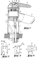
- valve 1 shows a sanitary fitting which has a fitting housing 1.
- the valve body 1 is on the Top of a plate 2 attached in the area of a through hole 3.
- the valve housing 1 is placed on the top of the plate 2 and screwed from the bottom with the aid of a set screw 4 and a nut 5 screwed onto the set screw 4.
- two hoses 7 are passed through the hole 3, one for cold water and one for warm water.
- the two hoses are inserted into the valve housing 1 with the aid of nipples 8. They lead into a receiving space 9, in which a valve cartridge 10 is arranged in the example shown.
- the valve cartridge contains a control lever 11 which protrudes upward from the valve body 1 and is connected there with an actuating handle 12. With the help of the control lever 1, the mixing ratio between warm and cold water and the amount of mixed water is determined depending on its position. This mixed water emerges from the fitting outlet 13.
- a connecting element 15 is screwed with the aid of a screw 14.
- the connecting element 15, which will be shown in more detail, rests on two opposite sides on the outside of the control lever 11 and is screwed by the head of the screw 14 against the free end face of the control lever 11.
- the connecting element 15 has a laterally bent extension 16 which extends at an angle of approximately 45 ° with respect to the longitudinal axis of the control lever 11. This approach 16 rests on a shoulder 17 recessed inside the actuating handle 12.
- a grub screw 18 is guided with the aid of a thread in a passage, the inward free end of which is on the side of the shoulder 16 of the connecting element opposite the shoulder 17 15 lies flat.
- the shoulder 16 is clamped against this shoulder 17 and thereby the actuating handle 12 is fixed on the connecting element 15.
- a movement of the actuation handle 12 therefore leads to a pivoting or twisting of the control lever 11 and thus to an actuation of the valve cartridge 10.
- the actuating handle 12 is designed such that the connecting element rests on at least three sides on the surfaces of a recess 19 in the actuating handle. In other words, the operating handle 12 can first be pushed onto the connecting element 15 until it reaches the end position shown. In this end position, the jamming takes place by tightening the grub screw 18.
- FIG. 2 shows, on a larger scale than in FIG. 1, a view of the connecting element 15 from the right in FIG. 1.
- the connecting element 15 is made in one piece from a piece of metal by stamping and bending. It has the U shape shown in FIG. 2, the two legs 20 running parallel to one another and being connected to one another by the web 21.
- two inwardly directed lugs 22 are formed, which also serve for a positive connection with the control lever 11.
- a central hole 23 is formed in the web 21, through which the screw 14 has matured.
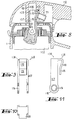
- FIG. 5 shows a representation corresponding to FIG. 1 in a second embodiment.
- the connecting element 25 is mounted on the pivot axis of the control lever 11.
- the legs 26 have a width which is smaller than the width of the control lever 11 measured in the same direction, so that the legs 26 can come to lie in depressions in the sides of the control lever 11.
- the fastening takes place in turn with the aid of the fastening screw 14 which is screwed into a threaded bore running in the axial direction of the control lever 11. Due to the positive connection, the fastening screw can also be omitted.
- the connecting element 25 has a lateral extension 28, which also starts from the web of the connecting element 25, but is bent in the direction of the control lever 11.
- the end of the grub screw 18 engages the surface 29 of the shoulder 28.
- the shoulder 28 is jammed between the control lever 11 and the grub screw 18 of the actuating handle 12.
- control lever 11 together with the connecting element 25 by overmolding the connecting element 25.
- the connecting element is designed as an essentially U-shaped bracket, the legs of which bear flat against the outside of the control lever 11 and the web of which is screwed tight by the fastening screw 14, in the following embodiments in FIG. 6, the connecting element is formed so that it has a sleeve portion which contacts the free end of the control lever 11 along a closed circumference on all sides.
- a one-piece connecting element 35 is provided, which has a circular disk 36.
- a sleeve-like, cylindrical extension 37 is formed in the center on the underside of the disk 36 facing the valve cartridge 10, the inside shape and dimensions of which correspond to the outside shape and dimensions of the control lever 11.
- An apron 38 is formed concentrically on the outside of the disk 36, the axial length of which is approximately half as long as that of the sleeve extension 37. At the end of the apron 38, a flange-like extension 39 directed radially outward is formed.
- the inside of the handle 12 contains a recess complementary to the outer shape of the connecting element 35.
- the outside of the flange 39, the step formed at the transition between the flange 39 and the apron 38, the outside of the apron 38 and the top of the disk 36 in its edge region lie against corresponding mating surfaces of the recess 19 in the actuating handle 12.
- the disk 36 contains an opening in the center through which the screw 14 extends.
- the screw 14 in turn serves to screw the connecting element 15 onto the control lever 11.
- a plurality of individual tongues 40 extending over a partial circumference are formed on the upper side of the disk 36, the outer sides of which are formed like barbs. They engage in a corresponding undercut 41 of the recess 19.
- the tongues 40 are separated from one another by individual incisions 42 so that they can spring inwards.
- the connecting element with the exception of the tongues 40, is constructed similarly to the embodiment according to FIG. 6. Again, the connecting element 45 is guided in the recess 19 by appropriate dimensioning.
- a lateral resilient projection 46 is formed on the connecting element 45 and engages in a through opening 47 in the actuating handle 12.
- several such resilient projections 46 can also be present.
- the latching can be released with the aid of a tool.
- FIG. 8 shows the upper part of a sanitary fitting, in which a mixer cartridge 10 is arranged in a fitting body 1, in a highly schematic manner.
- the mixer cartridge is actuated with the aid of a control lever 103, which protrudes from the valve body 1 on the top in the example shown.
- the control lever 103 can be pivoted about the axis of a shaft 104. At the same time, it can be used to perform a second control movement by rotating about the axis of the valve cartridge 102.
- a connecting element 106 which is approximately U-shaped and has two legs, is snapped onto the free end 105 107, which extend to the shaft 104 and are provided with openings there.
- a tab-like extension 109 is formed on the side of the connecting element 106, is bent in the direction of the shaft 104 and forms a flat contact surface 110 for a fastening screw 111 there.
- the contact surface 110 extends obliquely with respect to the outside of the control lever 103 and in such a way that the contact surface 110, starting from the free end of the control lever 103, approaches the shaft 104 of the longitudinal axis of the control lever 103.
- the fastening screw 111 is screwed into an oblique threaded bore of an actuating handle 112 and engages with its free, flat end on the contact surface 110.
- the actuating handle is screwed onto the connecting element and thus onto the control lever 103.
- the actuating handle 112 has on its inside or underside facing the control lever 103 a receptacle 113 which is adapted in cross section to the cross-sectional shape of the control lever 103 so that when the valve cartridge 102 is rotated about the axis of the valve lever 102, the control lever 103 is carried in a form-fitting manner .
- the fastening screw 111 is primarily a screw for preventing pulling or for eliminating play.
- FIG. 9 shows a view of the connecting element 106 of FIG. 8 from the right in a slightly enlarged scale.
- the two legs 107 run parallel to one another and thereby form a space in which the control lever 103 comes to rest.
- the legs 107 each have one in their free end region Opening 114 for the shaft 104 which serves to pivot the control lever 103.
- FIG. 11 shows an enlarged illustration of the connecting element from the same direction as in FIG. 8.
- the legs 107 are widened somewhat in the region of the openings 114, so that an outer contour 116 which is coaxial with the opening 114 is produced.
- a connecting element 117 is provided which is approximately hat-shaped. It has a flat disk 118, in the center of which a cylindrical projection 119 is formed on the underside facing the valve cartridge 102.
- the cross section of the cylindrical extension 119 corresponds approximately to the cross section of the free end 105 of the control lever.
- a barb-like profile 120 is formed on the cylindrical extension 119 inward in the region of its open end, which snaps into a corresponding recess in the control lever 103.
- An apron 121 is formed on the outer circumference of the disk 118, which is circular or also deviates from the circular shape can be. This apron 121 lies with its outside on the inside of the receptacle 122 in the operating handle 112.
- the apron 121 continues on its underside in a radially outwardly directed shoulder 123 which also bears on a corresponding contact surface 124 of the handle 112. In this way, a positive and non-positive connection between the operating handle 112 and the connecting element 117 is created.
- a finger 125 is formed on the inside of the receptacle 122, which extends through an opening 126 in the disk 118 of the connecting element 117 and bears on the outside of the cylindrical projection 119 at the point where the barb-like profile 120 is formed on the inside. This also prevents unintentional loosening of the connecting element by disengaging.
- a resilient extension 127 is formed on the right in FIG. 12 and engages with its free end 128 in a corresponding opening 129 in the actuating handle. This detent can be released again by pushing the free end 128 inwards with a tool inserted into the opening 129, for example a pin.
- the actuation handle 112 is attached in the embodiment according to FIG. 12 in two stages. First of all, the connecting element 117 is pushed onto the free end 105 of the control lever 103, the barb-like profile 120 being oriented such that it corresponds to the corresponding notch of the control lever 103. When pushed on, the barb-like profile 120 springs slightly outwards and slides over the side wall of the control lever 103 until it finally snaps into the notch. This provides the connection between the connecting element 117 and the control lever 103. Then, again from the top, the actuating handle 112 is pressed onto the outside of the connecting element 118, the finger 125 reaching through the opening 126 and preventing the connecting element 117 from being released from the control lever 103.
- the free end 128 of the resilient latching lug 127 comes to lie in the opening 129, as a result of which the actuating handle 112 is now also prevented from being pulled off the connecting element 117.
- the actuating handle 112 is thus positively and non-positively fixed on the connecting element 117, which in turn is positively and non-positively fixed on the control lever 103.
- FIG. 13 shows an embodiment similar to FIG. 12, in which a connecting element 130 similar to the connecting element 106 of FIG. 8 is used.
- the connecting element 130 is again U-shaped and contains a web 131 which connects two parallel legs 132 to one another. On the inside of the legs 132, an extension 133 is formed in the area of its free end, which engages in a corresponding notch of the control lever 103.
- the connecting element 131 is pushed on again from the free end of the control lever 103.
- the actuating handle 112 is pushed onto the connecting element, which in turn has a receptacle 134 on its inside.
- the receptacle 134 is adapted to the cross-sectional shape of the connecting element 130.
- the side walls of the connecting element can be connected to one another in the region of the sides. It is also possible that when the connecting element is in contact on all four sides, the side walls of the connecting element are connected to one another in pairs, so that two slots are formed which make it easier to snap on.
- the securing can take place in that the receptacle lies flat in the handle on the outside of the connecting element and thereby prevents the projections from moving out of the recesses.
- the connecting element 61 has the shape of a flat disk or a flat ring element which contains incisions 62 in the region of its outer surface.
- the incisions start from the free edge of the connecting element 61 and initially run axially, but then merge into a section 64 in which they run approximately along the circumference.
- a small undercut can be formed in the end region of the sections 64.
- the inner opening of the handle 60 contains individual projections 65 which are designed to engage the incisions 62.
Landscapes
- Engineering & Computer Science (AREA)
- General Engineering & Computer Science (AREA)
- Public Health (AREA)
- Health & Medical Sciences (AREA)
- Life Sciences & Earth Sciences (AREA)
- Hydrology & Water Resources (AREA)
- Mechanical Engineering (AREA)
- Water Supply & Treatment (AREA)
- Mechanically-Actuated Valves (AREA)
- Preventing Unauthorised Actuation Of Valves (AREA)
- Supports For Pipes And Cables (AREA)
- Feeding And Controlling Fuel (AREA)
- Infusion, Injection, And Reservoir Apparatuses (AREA)
- Mechanical Control Devices (AREA)
Applications Claiming Priority (2)
| Application Number | Priority Date | Filing Date | Title |
|---|---|---|---|
| DE19602161A DE19602161A1 (de) | 1996-01-23 | 1996-01-23 | Sanitärarmatur |
| DE19602161 | 1996-01-23 |
Publications (2)
| Publication Number | Publication Date |
|---|---|
| EP0786614A1 true EP0786614A1 (fr) | 1997-07-30 |
| EP0786614B1 EP0786614B1 (fr) | 2003-04-02 |
Family
ID=7783359
Family Applications (1)
| Application Number | Title | Priority Date | Filing Date |
|---|---|---|---|
| EP97100998A Expired - Lifetime EP0786614B1 (fr) | 1996-01-23 | 1997-01-23 | Vanne sanitaire |
Country Status (5)
| Country | Link |
|---|---|
| EP (1) | EP0786614B1 (fr) |
| AT (1) | ATE236370T1 (fr) |
| DE (2) | DE19602161A1 (fr) |
| DK (1) | DK0786614T3 (fr) |
| ES (1) | ES2194130T3 (fr) |
Cited By (2)
| Publication number | Priority date | Publication date | Assignee | Title |
|---|---|---|---|---|
| WO2009098569A1 (fr) * | 2008-02-04 | 2009-08-13 | Dlm International | Robinet a composition variable |
| WO2024199854A1 (fr) * | 2023-03-27 | 2024-10-03 | Grohe Ag | Appareil sanitaire |
Families Citing this family (3)
| Publication number | Priority date | Publication date | Assignee | Title |
|---|---|---|---|---|
| DE19913214A1 (de) * | 1999-03-24 | 2000-09-28 | Grohe Armaturen Friedrich | Ventilkartuschenanordnung |
| DE102008022410A1 (de) | 2008-05-06 | 2009-11-12 | Grohe Ag | Sanitärarmatur |
| DE102009011560A1 (de) * | 2009-03-06 | 2010-09-16 | Hansa Metallwerke Ag | Sanitäre Einhand-Mischbatterie |
Citations (4)
| Publication number | Priority date | Publication date | Assignee | Title |
|---|---|---|---|---|
| EP0092863A1 (fr) * | 1982-04-26 | 1983-11-02 | Gevipi A.G. | Dispositif de raccordement du levier d'un robinet mélangeur à monocommande |
| DE9017658U1 (de) * | 1990-10-06 | 1991-05-08 | Fa. Kludi-Armaturen Paul Scheffer, 5758 Fröndenberg | Auf einen Vierkantstift aufsteckbarer Bedienungshebel für eine sanitäre Mischbatterie |
| EP0579111A1 (fr) * | 1992-07-14 | 1994-01-19 | Friedrich Grohe Aktiengesellschaft | Mitigeur à commande unique |
| DE4343572A1 (de) * | 1993-12-21 | 1995-06-22 | Grohe Armaturen Friedrich | Hebelmischventil |
Family Cites Families (7)
| Publication number | Priority date | Publication date | Assignee | Title |
|---|---|---|---|---|
| DE7421886U (de) * | 1974-10-31 | Ideal Standard Gmbh | Griff für sanitäre Wasserventile | |
| DE3428287A1 (de) * | 1984-08-01 | 1986-02-13 | Hansa Metallwerke Ag | Einhebelmischer |
| DE3531109A1 (de) * | 1985-03-18 | 1987-03-12 | Rosenthal Ag | Sanitaeres absperr- oder mischventil sowie verfahren und vorrichtung zu seiner herstellung |
| DE8507951U1 (de) * | 1985-03-18 | 1985-05-15 | Ideal-Standard Gmbh, 5300 Bonn | Sanitäres Absperr- oder Mischventil |
| DE8704009U1 (de) * | 1987-03-17 | 1987-05-14 | Rubinetterie Rapetti S.p.A., Castiglione delle Stiviere, Mantova | Einhebelmischventil |
| DE3903997A1 (de) * | 1989-02-10 | 1990-08-16 | Grohe Armaturen Friedrich | Mischventil fuer sanitaerarmaturen |
| DE4113878C2 (de) * | 1990-05-10 | 1995-04-27 | Grohe Armaturen Friedrich | Betätigungsgriff für Einhebelmischer |
-
1996
- 1996-01-23 DE DE19602161A patent/DE19602161A1/de not_active Withdrawn
-
1997
- 1997-01-23 DE DE59709658T patent/DE59709658D1/de not_active Expired - Fee Related
- 1997-01-23 AT AT97100998T patent/ATE236370T1/de not_active IP Right Cessation
- 1997-01-23 EP EP97100998A patent/EP0786614B1/fr not_active Expired - Lifetime
- 1997-01-23 DK DK97100998T patent/DK0786614T3/da active
- 1997-01-23 ES ES97100998T patent/ES2194130T3/es not_active Expired - Lifetime
Patent Citations (5)
| Publication number | Priority date | Publication date | Assignee | Title |
|---|---|---|---|---|
| EP0092863A1 (fr) * | 1982-04-26 | 1983-11-02 | Gevipi A.G. | Dispositif de raccordement du levier d'un robinet mélangeur à monocommande |
| DE9017658U1 (de) * | 1990-10-06 | 1991-05-08 | Fa. Kludi-Armaturen Paul Scheffer, 5758 Fröndenberg | Auf einen Vierkantstift aufsteckbarer Bedienungshebel für eine sanitäre Mischbatterie |
| EP0579111A1 (fr) * | 1992-07-14 | 1994-01-19 | Friedrich Grohe Aktiengesellschaft | Mitigeur à commande unique |
| DE4223093A1 (de) | 1992-07-14 | 1994-01-20 | Grohe Armaturen Friedrich | Eingriffmischventil |
| DE4343572A1 (de) * | 1993-12-21 | 1995-06-22 | Grohe Armaturen Friedrich | Hebelmischventil |
Cited By (2)
| Publication number | Priority date | Publication date | Assignee | Title |
|---|---|---|---|---|
| WO2009098569A1 (fr) * | 2008-02-04 | 2009-08-13 | Dlm International | Robinet a composition variable |
| WO2024199854A1 (fr) * | 2023-03-27 | 2024-10-03 | Grohe Ag | Appareil sanitaire |
Also Published As
| Publication number | Publication date |
|---|---|
| DE19602161A1 (de) | 1997-07-24 |
| DK0786614T3 (da) | 2003-07-28 |
| DE59709658D1 (de) | 2003-05-08 |
| ES2194130T3 (es) | 2003-11-16 |
| EP0786614B1 (fr) | 2003-04-02 |
| ATE236370T1 (de) | 2003-04-15 |
Similar Documents
| Publication | Publication Date | Title |
|---|---|---|
| DE19647742C2 (de) | Einrichtungs-Anziehvorrichtung für unverlierbare Schrauben | |
| DE10338621A1 (de) | Federbelasteter Rastbolzen | |
| DE3843095A1 (de) | Befestigungseinrichtung fuer verkleidungen | |
| EP1916740A1 (fr) | Commutateur d'installation et borne par serrage pour un commutateur d'installation | |
| CH673686A5 (fr) | ||
| EP0786614B1 (fr) | Vanne sanitaire | |
| DE4201570C2 (de) | Stellvorrichtung | |
| WO2005068884A1 (fr) | Robinet sanitaire | |
| EP0754827A2 (fr) | Dispositif pour la fixation amovible et axialement non coulissante d'une poignée sur un élément de palier, notamment pour une poignée de porte ou fenêtre | |
| EP4012200A1 (fr) | Boulon d'encliquetage sollicité par ressort | |
| EP1004711A2 (fr) | Rosette de couverture | |
| DE2142488A1 (de) | Lösbarer Schraubverbinddr, insbesondere zum Anschluß von Tafeln an Rahmen od. dgl | |
| DE10114855C2 (de) | Sanitäre Auslaufarmatur | |
| EP0855544A2 (fr) | Mitigeur monocommande | |
| EP1597451B1 (fr) | Serrure a pene rotatif | |
| DE19912324A1 (de) | Sanitärarmatur mit einer Mutter zur Befestigung | |
| EP2226540A1 (fr) | Armature encastrée sanitaire | |
| DE3019784A1 (de) | Vorrichtung zur schraubbefestigung von flachteilen | |
| DE1703318A1 (de) | Beschlag fuer Tueren,Fenster od.dgl. | |
| DE19501313A1 (de) | Seitenbrause | |
| DE8602370U1 (de) | Ab- und Überlaufarmatur für Badewannen, Brausewannen od. dgl. | |
| DE29715582U1 (de) | Schaltknauf zur Befestigung auf dem freien Ende eines Getriebe-Schalthebels für Kraftfahrzeuge | |
| EP0786613B1 (fr) | Fixation d'un levier de commande à une vanne sanitaire | |
| DE3426050A1 (de) | Betaetigungsgriff fuer armaturen | |
| DE10161176C2 (de) | Befestigungszusammensetzung für ein mit einer Bohrung versehenes Werkstück |
Legal Events
| Date | Code | Title | Description |
|---|---|---|---|
| PUAI | Public reference made under article 153(3) epc to a published international application that has entered the european phase |
Free format text: ORIGINAL CODE: 0009012 |
|
| AK | Designated contracting states |
Kind code of ref document: A1 Designated state(s): AT BE CH DE DK ES FI FR GB IT LI NL SE |
|
| 17P | Request for examination filed |
Effective date: 19970705 |
|
| 17Q | First examination report despatched |
Effective date: 19990720 |
|
| GRAH | Despatch of communication of intention to grant a patent |
Free format text: ORIGINAL CODE: EPIDOS IGRA |
|
| GRAH | Despatch of communication of intention to grant a patent |
Free format text: ORIGINAL CODE: EPIDOS IGRA |
|
| RAP1 | Party data changed (applicant data changed or rights of an application transferred) |
Owner name: HANSGROHE AG |
|
| GRAA | (expected) grant |
Free format text: ORIGINAL CODE: 0009210 |
|
| AK | Designated contracting states |
Designated state(s): AT BE CH DE DK ES FI FR GB IT LI NL SE |
|
| PG25 | Lapsed in a contracting state [announced via postgrant information from national office to epo] |
Ref country code: NL Free format text: LAPSE BECAUSE OF FAILURE TO SUBMIT A TRANSLATION OF THE DESCRIPTION OR TO PAY THE FEE WITHIN THE PRESCRIBED TIME-LIMIT Effective date: 20030402 Ref country code: FI Free format text: LAPSE BECAUSE OF FAILURE TO SUBMIT A TRANSLATION OF THE DESCRIPTION OR TO PAY THE FEE WITHIN THE PRESCRIBED TIME-LIMIT Effective date: 20030402 |
|
| REG | Reference to a national code |
Ref country code: GB Ref legal event code: FG4D Free format text: NOT ENGLISH |
|
| REG | Reference to a national code |
Ref country code: CH Ref legal event code: NV Representative=s name: TROESCH SCHEIDEGGER WERNER AG Ref country code: CH Ref legal event code: EP |
|
| REF | Corresponds to: |
Ref document number: 59709658 Country of ref document: DE Date of ref document: 20030508 Kind code of ref document: P |
|
| GBT | Gb: translation of ep patent filed (gb section 77(6)(a)/1977) |
Effective date: 20030519 |
|
| PG25 | Lapsed in a contracting state [announced via postgrant information from national office to epo] |
Ref country code: SE Free format text: LAPSE BECAUSE OF FAILURE TO SUBMIT A TRANSLATION OF THE DESCRIPTION OR TO PAY THE FEE WITHIN THE PRESCRIBED TIME-LIMIT Effective date: 20030702 |
|
| REG | Reference to a national code |
Ref country code: DK Ref legal event code: T3 |
|
| NLV1 | Nl: lapsed or annulled due to failure to fulfill the requirements of art. 29p and 29m of the patents act | ||
| ET | Fr: translation filed | ||
| REG | Reference to a national code |
Ref country code: ES Ref legal event code: FG2A Ref document number: 2194130 Country of ref document: ES Kind code of ref document: T3 |
|
| PG25 | Lapsed in a contracting state [announced via postgrant information from national office to epo] |
Ref country code: AT Free format text: LAPSE BECAUSE OF NON-PAYMENT OF DUE FEES Effective date: 20040123 |
|
| PG25 | Lapsed in a contracting state [announced via postgrant information from national office to epo] |
Ref country code: BE Free format text: LAPSE BECAUSE OF NON-PAYMENT OF DUE FEES Effective date: 20040131 |
|
| PLBE | No opposition filed within time limit |
Free format text: ORIGINAL CODE: 0009261 |
|
| STAA | Information on the status of an ep patent application or granted ep patent |
Free format text: STATUS: NO OPPOSITION FILED WITHIN TIME LIMIT |
|
| 26N | No opposition filed |
Effective date: 20040105 |
|
| BERE | Be: lapsed |
Owner name: *HANSGROHE A.G. Effective date: 20040131 |
|
| PGFP | Annual fee paid to national office [announced via postgrant information from national office to epo] |
Ref country code: ES Payment date: 20080125 Year of fee payment: 12 Ref country code: DK Payment date: 20080124 Year of fee payment: 12 Ref country code: CH Payment date: 20080124 Year of fee payment: 12 |
|
| PGFP | Annual fee paid to national office [announced via postgrant information from national office to epo] |
Ref country code: IT Payment date: 20080126 Year of fee payment: 12 Ref country code: GB Payment date: 20080123 Year of fee payment: 12 Ref country code: DE Payment date: 20080123 Year of fee payment: 12 |
|
| PGFP | Annual fee paid to national office [announced via postgrant information from national office to epo] |
Ref country code: FR Payment date: 20080118 Year of fee payment: 12 |
|
| REG | Reference to a national code |
Ref country code: CH Ref legal event code: PL |
|
| GBPC | Gb: european patent ceased through non-payment of renewal fee |
Effective date: 20090123 |
|
| REG | Reference to a national code |
Ref country code: DK Ref legal event code: EBP |
|
| PG25 | Lapsed in a contracting state [announced via postgrant information from national office to epo] |
Ref country code: LI Free format text: LAPSE BECAUSE OF NON-PAYMENT OF DUE FEES Effective date: 20090131 Ref country code: DE Free format text: LAPSE BECAUSE OF NON-PAYMENT OF DUE FEES Effective date: 20090801 Ref country code: CH Free format text: LAPSE BECAUSE OF NON-PAYMENT OF DUE FEES Effective date: 20090131 |
|
| REG | Reference to a national code |
Ref country code: FR Ref legal event code: ST Effective date: 20091030 |
|
| PG25 | Lapsed in a contracting state [announced via postgrant information from national office to epo] |
Ref country code: GB Free format text: LAPSE BECAUSE OF NON-PAYMENT OF DUE FEES Effective date: 20090123 |
|
| REG | Reference to a national code |
Ref country code: ES Ref legal event code: FD2A Effective date: 20090124 |
|
| PG25 | Lapsed in a contracting state [announced via postgrant information from national office to epo] |
Ref country code: FR Free format text: LAPSE BECAUSE OF NON-PAYMENT OF DUE FEES Effective date: 20090202 Ref country code: ES Free format text: LAPSE BECAUSE OF NON-PAYMENT OF DUE FEES Effective date: 20090124 |
|
| PG25 | Lapsed in a contracting state [announced via postgrant information from national office to epo] |
Ref country code: DK Free format text: LAPSE BECAUSE OF NON-PAYMENT OF DUE FEES Effective date: 20090731 |
|
| PG25 | Lapsed in a contracting state [announced via postgrant information from national office to epo] |
Ref country code: IT Free format text: LAPSE BECAUSE OF NON-PAYMENT OF DUE FEES Effective date: 20090123 |