EP0786632B1 - Système de réfrigération avec soupape de commande de pression - Google Patents
Système de réfrigération avec soupape de commande de pression Download PDFInfo
- Publication number
- EP0786632B1 EP0786632B1 EP97101045A EP97101045A EP0786632B1 EP 0786632 B1 EP0786632 B1 EP 0786632B1 EP 97101045 A EP97101045 A EP 97101045A EP 97101045 A EP97101045 A EP 97101045A EP 0786632 B1 EP0786632 B1 EP 0786632B1
- Authority
- EP
- European Patent Office
- Prior art keywords
- pressure
- valve
- chamber
- refrigerant
- pressure control
- Prior art date
- Legal status (The legal status is an assumption and is not a legal conclusion. Google has not performed a legal analysis and makes no representation as to the accuracy of the status listed.)
- Expired - Lifetime
Links
Images



Classifications
-
- C—CHEMISTRY; METALLURGY
- C09—DYES; PAINTS; POLISHES; NATURAL RESINS; ADHESIVES; COMPOSITIONS NOT OTHERWISE PROVIDED FOR; APPLICATIONS OF MATERIALS NOT OTHERWISE PROVIDED FOR
- C09K—MATERIALS FOR MISCELLANEOUS APPLICATIONS, NOT PROVIDED FOR ELSEWHERE
- C09K5/00—Heat-transfer, heat-exchange or heat-storage materials, e.g. refrigerants; Materials for the production of heat or cold by chemical reactions other than by combustion
- C09K5/02—Materials undergoing a change of physical state when used
- C09K5/04—Materials undergoing a change of physical state when used the change of state being from liquid to vapour or vice versa
- C09K5/041—Materials undergoing a change of physical state when used the change of state being from liquid to vapour or vice versa for compression-type refrigeration systems
-
- F—MECHANICAL ENGINEERING; LIGHTING; HEATING; WEAPONS; BLASTING
- F25—REFRIGERATION OR COOLING; COMBINED HEATING AND REFRIGERATION SYSTEMS; HEAT PUMP SYSTEMS; MANUFACTURE OR STORAGE OF ICE; LIQUEFACTION SOLIDIFICATION OF GASES
- F25B—REFRIGERATION MACHINES, PLANTS OR SYSTEMS; COMBINED HEATING AND REFRIGERATION SYSTEMS; HEAT PUMP SYSTEMS
- F25B13/00—Compression machines, plants or systems, with reversible cycle
-
- F—MECHANICAL ENGINEERING; LIGHTING; HEATING; WEAPONS; BLASTING
- F25—REFRIGERATION OR COOLING; COMBINED HEATING AND REFRIGERATION SYSTEMS; HEAT PUMP SYSTEMS; MANUFACTURE OR STORAGE OF ICE; LIQUEFACTION SOLIDIFICATION OF GASES
- F25B—REFRIGERATION MACHINES, PLANTS OR SYSTEMS; COMBINED HEATING AND REFRIGERATION SYSTEMS; HEAT PUMP SYSTEMS
- F25B41/00—Fluid-circulation arrangements
- F25B41/30—Expansion means; Dispositions thereof
- F25B41/31—Expansion valves
- F25B41/33—Expansion valves with the valve member being actuated by the fluid pressure, e.g. by the pressure of the refrigerant
- F25B41/335—Expansion valves with the valve member being actuated by the fluid pressure, e.g. by the pressure of the refrigerant via diaphragms
-
- F—MECHANICAL ENGINEERING; LIGHTING; HEATING; WEAPONS; BLASTING
- F25—REFRIGERATION OR COOLING; COMBINED HEATING AND REFRIGERATION SYSTEMS; HEAT PUMP SYSTEMS; MANUFACTURE OR STORAGE OF ICE; LIQUEFACTION SOLIDIFICATION OF GASES
- F25B—REFRIGERATION MACHINES, PLANTS OR SYSTEMS; COMBINED HEATING AND REFRIGERATION SYSTEMS; HEAT PUMP SYSTEMS
- F25B41/00—Fluid-circulation arrangements
- F25B41/30—Expansion means; Dispositions thereof
- F25B41/31—Expansion valves
- F25B41/34—Expansion valves with the valve member being actuated by electric means, e.g. by piezoelectric actuators
- F25B41/35—Expansion valves with the valve member being actuated by electric means, e.g. by piezoelectric actuators by rotary motors, e.g. by stepping motors
-
- F—MECHANICAL ENGINEERING; LIGHTING; HEATING; WEAPONS; BLASTING
- F25—REFRIGERATION OR COOLING; COMBINED HEATING AND REFRIGERATION SYSTEMS; HEAT PUMP SYSTEMS; MANUFACTURE OR STORAGE OF ICE; LIQUEFACTION SOLIDIFICATION OF GASES
- F25B—REFRIGERATION MACHINES, PLANTS OR SYSTEMS; COMBINED HEATING AND REFRIGERATION SYSTEMS; HEAT PUMP SYSTEMS
- F25B9/00—Compression machines, plants or systems, in which the refrigerant is air or other gas of low boiling point
- F25B9/002—Compression machines, plants or systems, in which the refrigerant is air or other gas of low boiling point characterised by the refrigerant
- F25B9/008—Compression machines, plants or systems, in which the refrigerant is air or other gas of low boiling point characterised by the refrigerant the refrigerant being carbon dioxide
-
- G—PHYSICS
- G05—CONTROLLING; REGULATING
- G05D—SYSTEMS FOR CONTROLLING OR REGULATING NON-ELECTRIC VARIABLES
- G05D16/00—Control of fluid pressure
- G05D16/04—Control of fluid pressure without auxiliary power
- G05D16/06—Control of fluid pressure without auxiliary power the sensing element being a flexible membrane, yielding to pressure, e.g. diaphragm, bellows, capsule
- G05D16/0616—Control of fluid pressure without auxiliary power the sensing element being a flexible membrane, yielding to pressure, e.g. diaphragm, bellows, capsule the sensing element being a bellow
- G05D16/0619—Control of fluid pressure without auxiliary power the sensing element being a flexible membrane, yielding to pressure, e.g. diaphragm, bellows, capsule the sensing element being a bellow acting directly on the obturator
-
- G—PHYSICS
- G05—CONTROLLING; REGULATING
- G05D—SYSTEMS FOR CONTROLLING OR REGULATING NON-ELECTRIC VARIABLES
- G05D16/00—Control of fluid pressure
- G05D16/04—Control of fluid pressure without auxiliary power
- G05D16/06—Control of fluid pressure without auxiliary power the sensing element being a flexible membrane, yielding to pressure, e.g. diaphragm, bellows, capsule
- G05D16/063—Control of fluid pressure without auxiliary power the sensing element being a flexible membrane, yielding to pressure, e.g. diaphragm, bellows, capsule the sensing element being a membrane
- G05D16/0644—Control of fluid pressure without auxiliary power the sensing element being a flexible membrane, yielding to pressure, e.g. diaphragm, bellows, capsule the sensing element being a membrane the membrane acting directly on the obturator
-
- C—CHEMISTRY; METALLURGY
- C09—DYES; PAINTS; POLISHES; NATURAL RESINS; ADHESIVES; COMPOSITIONS NOT OTHERWISE PROVIDED FOR; APPLICATIONS OF MATERIALS NOT OTHERWISE PROVIDED FOR
- C09K—MATERIALS FOR MISCELLANEOUS APPLICATIONS, NOT PROVIDED FOR ELSEWHERE
- C09K2205/00—Aspects relating to compounds used in compression type refrigeration systems
- C09K2205/10—Components
- C09K2205/106—Carbon dioxide
-
- F—MECHANICAL ENGINEERING; LIGHTING; HEATING; WEAPONS; BLASTING
- F25—REFRIGERATION OR COOLING; COMBINED HEATING AND REFRIGERATION SYSTEMS; HEAT PUMP SYSTEMS; MANUFACTURE OR STORAGE OF ICE; LIQUEFACTION SOLIDIFICATION OF GASES
- F25B—REFRIGERATION MACHINES, PLANTS OR SYSTEMS; COMBINED HEATING AND REFRIGERATION SYSTEMS; HEAT PUMP SYSTEMS
- F25B2309/00—Gas cycle refrigeration machines
- F25B2309/06—Compression machines, plants or systems characterised by the refrigerant being carbon dioxide
- F25B2309/061—Compression machines, plants or systems characterised by the refrigerant being carbon dioxide with cycle highest pressure above the supercritical pressure
-
- F—MECHANICAL ENGINEERING; LIGHTING; HEATING; WEAPONS; BLASTING
- F25—REFRIGERATION OR COOLING; COMBINED HEATING AND REFRIGERATION SYSTEMS; HEAT PUMP SYSTEMS; MANUFACTURE OR STORAGE OF ICE; LIQUEFACTION SOLIDIFICATION OF GASES
- F25B—REFRIGERATION MACHINES, PLANTS OR SYSTEMS; COMBINED HEATING AND REFRIGERATION SYSTEMS; HEAT PUMP SYSTEMS
- F25B2313/00—Compression machines, plants or systems with reversible cycle not otherwise provided for
- F25B2313/031—Sensor arrangements
- F25B2313/0314—Temperature sensors near the indoor heat exchanger
-
- F—MECHANICAL ENGINEERING; LIGHTING; HEATING; WEAPONS; BLASTING
- F25—REFRIGERATION OR COOLING; COMBINED HEATING AND REFRIGERATION SYSTEMS; HEAT PUMP SYSTEMS; MANUFACTURE OR STORAGE OF ICE; LIQUEFACTION SOLIDIFICATION OF GASES
- F25B—REFRIGERATION MACHINES, PLANTS OR SYSTEMS; COMBINED HEATING AND REFRIGERATION SYSTEMS; HEAT PUMP SYSTEMS
- F25B2341/00—Details of ejectors not being used as compression device; Details of flow restrictors or expansion valves
- F25B2341/06—Details of flow restrictors or expansion valves
- F25B2341/063—Feed forward expansion valves
-
- F—MECHANICAL ENGINEERING; LIGHTING; HEATING; WEAPONS; BLASTING
- F25—REFRIGERATION OR COOLING; COMBINED HEATING AND REFRIGERATION SYSTEMS; HEAT PUMP SYSTEMS; MANUFACTURE OR STORAGE OF ICE; LIQUEFACTION SOLIDIFICATION OF GASES
- F25B—REFRIGERATION MACHINES, PLANTS OR SYSTEMS; COMBINED HEATING AND REFRIGERATION SYSTEMS; HEAT PUMP SYSTEMS
- F25B2600/00—Control issues
- F25B2600/02—Compressor control
- F25B2600/025—Compressor control by controlling speed
- F25B2600/0253—Compressor control by controlling speed with variable speed
-
- F—MECHANICAL ENGINEERING; LIGHTING; HEATING; WEAPONS; BLASTING
- F25—REFRIGERATION OR COOLING; COMBINED HEATING AND REFRIGERATION SYSTEMS; HEAT PUMP SYSTEMS; MANUFACTURE OR STORAGE OF ICE; LIQUEFACTION SOLIDIFICATION OF GASES
- F25B—REFRIGERATION MACHINES, PLANTS OR SYSTEMS; COMBINED HEATING AND REFRIGERATION SYSTEMS; HEAT PUMP SYSTEMS
- F25B2600/00—Control issues
- F25B2600/17—Control issues by controlling the pressure of the condenser
-
- F—MECHANICAL ENGINEERING; LIGHTING; HEATING; WEAPONS; BLASTING
- F25—REFRIGERATION OR COOLING; COMBINED HEATING AND REFRIGERATION SYSTEMS; HEAT PUMP SYSTEMS; MANUFACTURE OR STORAGE OF ICE; LIQUEFACTION SOLIDIFICATION OF GASES
- F25B—REFRIGERATION MACHINES, PLANTS OR SYSTEMS; COMBINED HEATING AND REFRIGERATION SYSTEMS; HEAT PUMP SYSTEMS
- F25B2700/00—Sensing or detecting of parameters; Sensors therefor
- F25B2700/21—Temperatures
- F25B2700/2104—Temperatures of an indoor room or compartment
-
- Y—GENERAL TAGGING OF NEW TECHNOLOGICAL DEVELOPMENTS; GENERAL TAGGING OF CROSS-SECTIONAL TECHNOLOGIES SPANNING OVER SEVERAL SECTIONS OF THE IPC; TECHNICAL SUBJECTS COVERED BY FORMER USPC CROSS-REFERENCE ART COLLECTIONS [XRACs] AND DIGESTS
- Y02—TECHNOLOGIES OR APPLICATIONS FOR MITIGATION OR ADAPTATION AGAINST CLIMATE CHANGE
- Y02B—CLIMATE CHANGE MITIGATION TECHNOLOGIES RELATED TO BUILDINGS, e.g. HOUSING, HOUSE APPLIANCES OR RELATED END-USER APPLICATIONS
- Y02B30/00—Energy efficient heating, ventilation or air conditioning [HVAC]
- Y02B30/70—Efficient control or regulation technologies, e.g. for control of refrigerant flow, motor or heating
-
- Y—GENERAL TAGGING OF NEW TECHNOLOGICAL DEVELOPMENTS; GENERAL TAGGING OF CROSS-SECTIONAL TECHNOLOGIES SPANNING OVER SEVERAL SECTIONS OF THE IPC; TECHNICAL SUBJECTS COVERED BY FORMER USPC CROSS-REFERENCE ART COLLECTIONS [XRACs] AND DIGESTS
- Y02—TECHNOLOGIES OR APPLICATIONS FOR MITIGATION OR ADAPTATION AGAINST CLIMATE CHANGE
- Y02P—CLIMATE CHANGE MITIGATION TECHNOLOGIES IN THE PRODUCTION OR PROCESSING OF GOODS
- Y02P20/00—Technologies relating to chemical industry
- Y02P20/10—Process efficiency
-
- Y—GENERAL TAGGING OF NEW TECHNOLOGICAL DEVELOPMENTS; GENERAL TAGGING OF CROSS-SECTIONAL TECHNOLOGIES SPANNING OVER SEVERAL SECTIONS OF THE IPC; TECHNICAL SUBJECTS COVERED BY FORMER USPC CROSS-REFERENCE ART COLLECTIONS [XRACs] AND DIGESTS
- Y02—TECHNOLOGIES OR APPLICATIONS FOR MITIGATION OR ADAPTATION AGAINST CLIMATE CHANGE
- Y02P—CLIMATE CHANGE MITIGATION TECHNOLOGIES IN THE PRODUCTION OR PROCESSING OF GOODS
- Y02P20/00—Technologies relating to chemical industry
- Y02P20/50—Improvements relating to the production of bulk chemicals
- Y02P20/54—Improvements relating to the production of bulk chemicals using solvents, e.g. supercritical solvents or ionic liquids
Definitions
- the present invention relates to a refrigerating system of a vapor compression type, provided with a pressure control valve for controlling a pressure of a refrigerant at an output side of a heat emitter.
- the present invention is suitably used for a refrigerating system where a carbon dioxide (CO 2 ), as a refrigerant, is used at a super critical region.
- CO 2 carbon dioxide
- Document EP-A-0 279 622 reveals a pressure control valve for use in a passageway for a refrigerant of a vapor compression type refrigerating system, said pressure control value comprising a partition wall for dividing the passageway into upstream and downstream chambers.
- Japanese Unexamined Patent Publication No. 7-18602 discloses a vapor compression type refrigerating system where carbon dioxide (CO 2 ) is used as a refrigerant in place of freon.
- the carbon dioxide has a critical temperature as low as 31°C, which makes it possible for the temperature of the carbon dioxide at the outlet of the heat emitter to be higher than the critical temperature, so that the carbon dioxide is prevented from being condensed even at the outlet of the heat emitter.
- a critical temperature as low as 31°C, which makes it possible for the temperature of the carbon dioxide at the outlet of the heat emitter to be higher than the critical temperature, so that the carbon dioxide is prevented from being condensed even at the outlet of the heat emitter.
- an increased difference in a enthalpy by condensing the refrigerant can not be obtained as is the case in the conventional refrigerating system using the freon.
- an increase in the pressure of the carbon dioxide at the outlet of the compressor i.e., the pressure at the inlet of the heat emitter
- an increase in the outlet pressure of the compressor may cause a coefficient of performance to be worsened.
- An object of the present invention is to provide a refrigerating system using as, a refrigerant, carbon dioxide and operating at a critical region, capable of obtaining an increased efficiency.
- Another object of the present invention is to provide a refrigerating system using as, a refrigerant, carbon dioxide and operating at a critical region, capable of controlling the temperature and the pressure at an outlet of a heat emitter to obtain an operation substantially along an optimum operating line.
- a deflector commences its deflection when the pressure at an upstream chamber is higher than the pressure in a sealingly closed chamber by a predetermined value, causing a valve member to open the valve port. Furthermore, a refrigerant is filled to a volume of said sealingly closed chamber as obtained when said valve member closes said valve port at a density in a range between a value of density of a saturated liquid state refrigerant of a temperature of 0°C and a value of density of a saturated liquid state refrigerant at the critical point. In this condition, the relationship between the pressure and the temperature of the refrigerant in the closed chamber substantially conforms to an optimum control line.
- the pressure control valve opens its valve port.
- the outlet pressure and the outlet temperature of the heat emitter is controlled substantially along the optimum control line.
- Fig. 1 schematically illustrates a refrigerating system of a vapor compression type, which is constructed by a compressor 1, a heat emitter 2, a pressure control valve (expansion valve) 3, a heat absorber (evaporator) 4 and an accumulator 5, which are connected with each other by means of pipes 6 so that a closed circuit for a refrigerant (CO 2 ) is constructed.
- the heat emitter 2 is arranged at a front portion of the vehicle, so that a large temperature difference is obtained between the outside air contacting the heat emitter and the carbon dioxide flowing in the heat emitter, thereby enhancing heat change efficiency.
- a fan 2-1 is arranged for generating a flow of the air for an effective emission of the heat from the heat emitter.
- the heat absorber 4 is arranged so as to be faced with a fan 4-1, which generates an air flow contacted with the heat absorber 4 and introduced into a cabin of a vehicle.
- a heat exchange is occurred between the carbon dioxide under a gas-liquid combined state and the air flow, causing the air flow to be cooled due to that fact that heat corresponding to a latent heat for evaporation is removed.
- the compressor 1 is connected to a drive means such an internal combustion engine or an electric motor, so that a rotating movement is transmitted to the compressor.
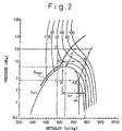
- a refrigerating cycle as executed by the system using the carbon dioxide as the refrigerant in Fig. 1 will now be explained. Namely, in a Mollier chart in Fig. 2, an abscissa shows an enthalpy, while ordinate shows a pressure of the refrigerant.
- a curve SL is a saturated line on which the refrigerant is under a equilibrium condition.
- the carbon dioxide is under a state designated by a point A in the Mollier chart in Fig. 2. Then, the gaseous state carbon dioxide is subjected to the compression at the compressor 1, so that the state of the refrigerant is moved to the one at a point B .
- the gaseous state carbon dioxide is subjected to a cooling at the heat emitter (gas cooler) 2, so that the emitted heat is taken by an air flow contacting the emitter, while the carbon dioxide is moved to a state designated by a point C in the Mollier chart. Then, the carbon dioxide is subjected to a pressure reduction at the pressure reducer 3, so that a gas-liquid combined state as designated by a point D in the Mollier chart is obtained. Finally, the gas-liquid combined state carbon dioxide is subjected to an evaporation at the evaporator 4, so that a flow of an air contacting with the evaporator 4 is cooled, while the carbon dioxide is moved to a gaseous state as designated by the point A for a repletion of the cycle.
- phase change from the gaseous state to the gas-combined state occurs when the pressure of the carbon dioxide is reduced below the one on the saturating curve SL, i.e., the pressure at crossing point of the curve SL with the line CD.
- the carbon dioxide has, however, a critical temperature (a temperature at the critical point X) of about 31°C, which is lower than the critical temperature of freon, such as R12, of about 112°C.
- a critical temperature a temperature at the critical point X
- freon such as R12
- a condition at the outlet of the heat emitter 2 as designated by the point C is determined by the outlet pressure of the compressor 1 and the temperature of the carbon dioxide at the outlet of the heat emitter 2.
- the temperature of the carbon dioxide at the outlet of the heat emitter 2 is determined by the heat emission capacity at the heat emitter 2 and the temperature of the outside air. It is clear that the outside air temperature is not controllable, which makes the temperature of the carbon dioxide to be uncontrollable at the outlet of the heat emitter.
- a control of the outlet pressure of the compressor which corresponds also to the pressure at the outlet of the heat emitter, is essential. Namely, in order to obtain a desired cooling capacity, i.e., an increased enthalpy difference under a condition of an increased outside air temperature in a summer season, it is essential that an outlet pressure of the compressor is increased to a value as designated by a point F in Fig. 2. In other words, the pressure at the outlet of the heat emitter 2 is increased to the value as designated by a point G in Fig. 2, so that the refrigerating cycle is executed in the order of E-F-G-H-E.
- an increase in a pressure at the outlet of the compressor 1 is necessary, which necessitates an increased work done by the compressor, which corresponds to a change ⁇ L in the enthalpy during the compression process.
- an increase in the enthalpy may cause a coefficient of performance COP to be reduced in a situation that the change ⁇ L in the enthalpy during the compression phase from the point A to the point B is larger than an increase ⁇ i in the change in the enthalpy during the evaporation phase from the point D to A .
- the coefficient of performance COP is calculated by ⁇ i/ ⁇ L.
- a result of a calculation of the COP by using the pressure of the carbon dioxide at the outlet of the heat emitter will now be explained.
- a solid curve in Fig. 3 shows a relationship between the pressure at the outlet of the heat emitter 2 and the value of the COP when the temperature of the carbon dioxide is 40°C. The maximum value of the COP is obtained at a pressure P 1 of about 10 MPa.
- a dotted curve in Fig. 3 shows a similar relationship when the temperature of the carbon dioxide is 35°C. The maximum value of the COP is obtained at a pressure P 2 of about 8.0 MPa.
- the pressure control valve 3 includes a valve cover 10, a diaphragm 11 and a valve housing 13.
- the diaphragm 11 is, at its outer periphery, sandwiched between the cover 10 and the housing 13, so that a closed chamber 12 is formed above the diaphragm 11 and an opened chamber 12' is formed below the diaphragm.
- the carbon dioxide is sealingly stored, while the volume of the carbon dioxide with respect to the volume of the chamber 12 as obtained at the seated state of the valve member 20 of the valve 1 is such that at a density of about 600 kg/m 3 of the carbon dioxide is obtained.
- the valve housing 13 is located in a section 6-1 of the recirculating pipe 6, so that a chamber 14 in communication with the heat emitter 2 for receiving the carbon dioxide therefrom is formed in the section 6-1 of the pipe 6 on the upper (upstream) side of the housing 13, while a chamber 15 in communication with the heat receiver 4 for issuing the carbon dioxide thereto is formed in the section 6-1 of the pipe 6 on the lower (downstream) side of the housing 13.
- the valve housing 13 is formed with a central bore 13-1 and a plate 16.
- the housing 6 is provided with a valve port 17 opened to the lower chamber 15, and diametrically opposite pair of communication holes 18 opened to the upper chamber 14.
- the pressure control valve 3 is further provided with a valve member 20, a valve spring 21 and a spacer 22.
- the valve member 20 has a bottom spherical end 20' facing the valve port 17 and a top end connected to the diaphragm 11 by a suitable conventional means, such as a nut (not shown).
- the spring 21 generates a spring force for urging the valve member 20 so that it is seated on the valve housing 13, thereby closing the valve port 17.
- the spacer 22 is for controlling a set force of the spring 21 to, for example, 1 MPa.
- an arrangement of the spacer 22 is such that the pressure at the central bore 13-1 in communication with the upper chamber 14 is opened to the lower diaphragm chamber 12'.
- a force is applied to the diaphragm 11 in accordance with the pressure difference between the upper and lower diaphragm chambers 12 and 12'. Namely, the pressure in the upper (closed) chamber 12 urges the diaphragm 11 to be moved downwardly, while the pressure in the lower chamber 12' opened to the chamber 14 urges the diaphragm 11 to be moved upwardly.
- the operation of the valve member 20 is controlled in accordance with the difference between the spring force and the force due to the pressure difference.
- Fig. 5 is a Mollier chart when the carbon dioxide (CO 2 ) is used and is same as that in Fig. 2.
- CO 2 carbon dioxide
- Fig. 5 in addition to the isothermal lines with numerals designating respective temperatures of CO 2 , isodensity lines with numerals designating respective density of CO 2 are shown.
- the carbon dioxide In the closed upper diaphragm chamber 12, the carbon dioxide is sealingly stored at a density of 600 kg/m 3 when measured by the volume of the chamber 12 as obtained under the seated condition of the valve member to the valve port 17.
- the pressure and the temperature of the carbon dioxide in the sealed chamber 12 are varied along the isodensity line with the numeral of 600.
- the pressure in the chamber 12 is 5.8 MPa, which is obtained as the pressure at the crossing point between the isothermal line of 20°C and isodensity line 600 kg/m 3 , which generates a force urging the valve member 20 to be seated on the valve seat.
- the set force of the spring 21 is about 1.0 MPa, which also generates a force urging the valve member 20 to be seated on the valve seat.
- valve member 20 when the pressure inside the lower chamber 12', which urges the diaphragm 11 upwardly, i.e., the valve member 20 to be detached from the valve seat, is lower than 6.8 MPa, the valve member 20 maintains its closed position where it is seated on the valve seat, which prevents the carbon dioxide from flowing from the chamber 14 into the chamber 15. Contrary to this, when the pressure inside the chamber 12' is higher than 6.8 MPa, the diaphragm 11 is moved upwardly, which causes the valve member 20 to be detached from the valve seat, which allows the carbon dioxide to flow from the chamber 14 to the chamber 15 via the valve port 17.
- the pressure control valve 3 is under the closed condition where the valve member 20 is seated on the valve seat, which prevent CO 2 in the upstream chamber 14 from flowing into the downstream chamber 15.
- the CO 2 stored in the accumulator 5 is "sucked" by the compressor 1, which allows the pressure at the outlet of the heat emitter 2 to be increased from the one as obtained due to a state of a change of condition from point b' to c' to the one as obtained due to a state of change from point b" to c".
- the closure of the pressure control valve causes the pressure at the outlet of the heat emitter 2 to be increased to a predetermined value, which is followed by the reduction of the pressure of CO 2 and the evaporation for cooling the air.
- the pressure control valve is under a closed condition when the pressure at the outlet of the heat emitter 2 is lower than about 6.8 MPa.
- the pressure at the outlet of the heat emitter exceeds the value of about 6.8 MPa causes the pressure control valve to be opened.
- the pressure control valve in the embodiment in Fig. 4 has an operating characteristic such that it is opened when the pressure at the outlet of the heat emitter 2 is increased to a predetermined value.
- the operating characteristic is determined in accordance with the pressure characteristic at the sealed chamber 12 of the pressure control valve.
- the isodensity curve at 600 kg/m 3 in the super critical area substantially conforms with the optimum control line ⁇ max.
- the pressure control valve in Fig. 4 operates to control the pressure along the optimum control line ⁇ max, so that an increased efficiency of execution of the refrigerating cycle is obtained by means of the refrigerating system.
- the sealing of the CO 2 in the chamber 12 is such that the density of the CO 2 is in a range between the density of the saturated liquid CO 2 when the temperature is 0°C and the density of the saturated liquid of CO 2 when the temperature is that of CO 2 at the critical point.
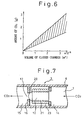
- the density is in a range between the isodensity line D 2 of 450 kg/m 3 and the isodensity line D 1 of 950 kg/m 3 .
- This range of the density of CO 2 corresponds to the shaded area of the amount of CO 2 in Fig. 6, which shows relationships between the volume of the sealed chamber 12 and the amount of the sealed CO 2 .
- the valve cover 10 and the valve housing 13 are made from a material of an increased heat conductivity for obtaining a conducted heat amount as large as possible.
- the valve cover and the valve housing are made from brass, while the diaphragm 11, the valve member 20 and the coil spring 21 are made from a stainless steel.
- valve cover 10 is advantageously formed with fins or a recess for increasing a heat transfer coefficient between the carbon dioxide in the space 14 and the valve cover 10.
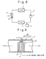
- Fig. 7 shows a modification of a pressure control valve 3 including a bellows member 23, in which the carbon dioxide is sealingly stored at a predetermined density.
- the bellows member is made of a brass material of an increased heat conductivity.
- a valve member 20 is connected to the bellows member 23 so that the valve member 20 is faced with a valve port 17 of the valve seat plate 16.
- a spring 21 for urging the valve member 20 toward the valve seat plate 16 is arranged in the sealed chamber 12 in the bellows member.
- An operation of the pressure control valve 3 in Fig. 7 is similar to that of the pressure control valve 3 in Fig. 4. Namely, a force due to the pressure of CO 2 stored in the chamber 12 plus the force of the spring 21 urges the valve member 20 to be seated on the valve seat 16.
- the pressure of CO 2 in the conduit section 6 causes the valve member 20 to be detached from the valve seat 16.
- the pressure of the CO 2 in the conduit 6 is controlled to the pressure of the CO 2 in the chamber 12 plus the set force of the spring 21, as similar to the first embodiment in Fig. 4.
- a third embodiment of the present invention is directed to a provision of a pressure control valve 3, which is electrically operated.
- the pressure control valve 3 is constructed essentially by a sensor 24 for detecting a difference of the pressure of the recirculated carbon dioxide from the sealed reference pressure and an electrically operated expansion valve 25 which is operated by an electrically operating signal. It is desirable that the sensor section 24 is at a location on one side of the expansion valve 25 adjacent to the heat emitter 2.
- the sensor section 24 includes a bellows 23 in which the carbon dioxide is sealingly stored at a predetermined density and a contact unit 26 constructed by a stationary contact 26-1 fixedly connected to the conduit 6 and a movable contact 26-2 connected to the bellows member 23 to face the stationary contact 26-1.
- the contact unit 26 is for controlling the operation of the expansion valve 25 via an amplifier (not shown).
- a pressure of CO 2 in the chamber 14 lower than the pressure in the sealed chamber 12 inside the bellows member 23 plus the set force of the spring 21 causes the bellows 23 to be inflated, thereby causing the contacts 26-1 and 26-2 to contact each other.
- the expansion valve 25 is controlled so that it is closed, thereby increasing the pressure at a location upstream from the pressure control valve 3.
- a pressure of CO 2 at the location upstream from the pressure control valve higher than the pressure in the sealed chamber 12 inside the bellows member 23 plus the set force of the spring 21 causes the bellows 23 to be deflated, thereby causing the contacts 26-1 and 26-2 to be detached from each other.
- the expansion valve 25 is controlled so that it is opened, thereby reducing the pressure at the location upstream from the pressure control valve.
- the spring 21 is used for generating an initial set force.
- an elastic force of the diaphragm or bellows can be used for generating the initial set force.
- a non-condensable gas together with the refrigerant (CO 2 ) can be sealed in the space 12.
Landscapes
- Engineering & Computer Science (AREA)
- Physics & Mathematics (AREA)
- Thermal Sciences (AREA)
- Mechanical Engineering (AREA)
- General Engineering & Computer Science (AREA)
- Chemical & Material Sciences (AREA)
- Fluid Mechanics (AREA)
- General Physics & Mathematics (AREA)
- Chemical Kinetics & Catalysis (AREA)
- Automation & Control Theory (AREA)
- Combustion & Propulsion (AREA)
- Materials Engineering (AREA)
- Organic Chemistry (AREA)
- Temperature-Responsive Valves (AREA)
- Safety Valves (AREA)
- Air-Conditioning For Vehicles (AREA)
- Devices That Are Associated With Refrigeration Equipment (AREA)
Claims (5)
- Une soupape de commande de pression à utiliser dans un passage pour un réfrigérant d'un système de réfrigération du type à compression de vapeur comprenant, en plus de la soupape de commande de pression (3), un compresseur (1), un émetteur de chaleur (2) et un évaporateur (4), ladite soupape de commande de pression étant placée en un endroit entre l'émetteur de chaleur (2) et l'évaporateur (4), ladite soupape de commande de pression comprenant :une cloison de séparation pour diviser ledit passage en une chambre amont (14) servant à recevoir le fluide frigorigène venant de l'émetteur de chaleur et en une chambre aval (15) délivrant le fluide réfrigérant à l'évaporateur ;ladite cloison de séparation définissant un orifice de soupape (17) situé entre les chambres amont et aval ;un déflecteur (11) contenant une chambre hermétiquement fermée (12) et assurant la déflexion en réponse à une différence de pression entre la chambre hermétiquement fermée (12) et la chambre amont (14); etun élément de soupape (20) pour commander une communication de la chambre amont (14) avec la chambre aval (15) par l'intermédiaire dudit orifice de soupape (17),ledit déflecteur commençant sa déflexion lorsqu'une pression au niveau de la chambre amont est supérieure d'une valeur prédéterminée à une pression dans la chambre hermétiquement fermée ;ledit déflecteur (11) étant relié audit élément de soupape (20) de manière telle que le commencement de la déflexion du déflecteur fasse que l'élément de soupape se détache de l'orifice de soupape ;ladite chambre hermétiquement fermée (12) étant remplie d'un volume dudit fluide frigorigène qui confère audit fluide frigorigène lorsque ledit élément de soupape (20) ferme ledit orifice de soupape (17) une masse volumique dans la plage de masse de volumique entre celle d'un fluide frigorigène à l'état liquide saturé à une température de 0° et celle d'un fluide frigorigène à l'état liquide saturé à son point critique ;et dans laquelle ledit fluide frigorigène est le dioxyde de carbone, et la masse volumique est dans une plage entre 450 kg/m3 et 950 kg/m3.
- Une soupape de commande de pression selon la revendication 1, dans laquelle ledit déflecteur comprend une membrane (11) reliée à l'élément de soupape (20), un carter (10) contenant la membrane (11) de sorte que la chambre hermétiquement fermée (12) soit formée sur un côté de la membrane, tandis que la membrane s'ouvre vers la chambre amont (14) du côté éloigné de la chambre hermétiquement fermée, et un ressort (21) pour solliciter l'élément de soupape de sorte que ce dernier ferme l'orifice de soupape (17).
- Une soupape de commande de pression selon la revendication 1, dans laquelle ledit déflecteur comprend un soufflet (25) qui contient une chambre comme étant ladite chambre hermétiquement fermée et qui est relié audit élément de soupape, un élément de support pour rendre le soufflet fixe à l'extrémité opposée à l'élément de soupape, et un ressort (21) pour solliciter l'élément de soupape (20) de sorte que ce dernier ferme l'orifice de soupape (17).
- Une soupape de commande de pression selon la revendication 1, dans laquelle ledit élément de soupape est du type à commande électrique, et dans laquelle ledit déflecteur comprend un élément de soufflet (23) qui y définit une chambre hermétiquement fermée (12), un contact mobile (26-2) relié à l'élément de soufflet, un contact fixe (26-1) qui est mis en face du contact mobile, et un ressort (21) pour solliciter les contacts pour qu'ils se touchent l'un l'autre, générant de ce fait un signal électrique faisant que l'élément de soupape ferme l'orifice de soupape, la pression de la chambre amont supérieure à celle dans la chambre hermétiquement fermée faisant que le contact mobile se détache du contact fixe, faisant que l'élément de soupape ouvre l'orifice de soupape.
- Un système de réfrigération comprenant :dans lequel le système de réfrigération comprend une soupape de commande de pression selon la revendication 1.un passage pour un fluide frigorigène ;un compresseur (1) pour comprimer le fluide frigorigène ;un émetteur de chaleur (2) pour refroidir le fluide frigorigène comprimé par le compresseur ;une soupape de commande de pression (3) pour réduire la pression du fluide frigorigène en une sortie dudit émetteur de chaleur ; etun évaporateur (4) pour évaporer de la soupape de commande de pression le fluide frigorigène ayant la pression réduite ;
Applications Claiming Priority (6)
| Application Number | Priority Date | Filing Date | Title |
|---|---|---|---|
| JP11248/96 | 1996-01-25 | ||
| JP1124896 | 1996-01-25 | ||
| JP1124896 | 1996-01-25 | ||
| JP33962/96 | 1996-02-21 | ||
| JP03396296A JP3858297B2 (ja) | 1996-01-25 | 1996-02-21 | 圧力制御弁と蒸気圧縮式冷凍サイクル |
| JP3396296 | 1996-02-21 |
Publications (3)
| Publication Number | Publication Date |
|---|---|
| EP0786632A2 EP0786632A2 (fr) | 1997-07-30 |
| EP0786632A3 EP0786632A3 (fr) | 1999-04-07 |
| EP0786632B1 true EP0786632B1 (fr) | 2003-05-28 |
Family
ID=26346664
Family Applications (1)
| Application Number | Title | Priority Date | Filing Date |
|---|---|---|---|
| EP97101045A Expired - Lifetime EP0786632B1 (fr) | 1996-01-25 | 1997-01-23 | Système de réfrigération avec soupape de commande de pression |
Country Status (4)
| Country | Link |
|---|---|
| US (1) | US5890370A (fr) |
| EP (1) | EP0786632B1 (fr) |
| JP (1) | JP3858297B2 (fr) |
| DE (1) | DE69722276T2 (fr) |
Cited By (1)
| Publication number | Priority date | Publication date | Assignee | Title |
|---|---|---|---|---|
| DE102005034709A1 (de) * | 2005-07-26 | 2007-02-01 | Daimlerchrysler Ag | Thermostatisches Expansionsventil |
Families Citing this family (69)
| Publication number | Priority date | Publication date | Assignee | Title |
|---|---|---|---|---|
| EP0837291B1 (fr) * | 1996-08-22 | 2005-01-12 | Denso Corporation | Système frigorifique du type à compression de vapeur |
| EP0892226B1 (fr) * | 1997-07-18 | 2005-09-14 | Denso Corporation | Soupape de commande de pression pour système frigorifique |
| JPH11211250A (ja) * | 1998-01-21 | 1999-08-06 | Denso Corp | 超臨界冷凍サイクル |
| DE19813673B4 (de) * | 1998-03-27 | 2004-01-29 | Daimlerchrysler Ag | Verfahren und Vorrichtung zum Heizen und Kühlen eines Nutzraumes eines Kraftfahrzeuges |
| JP3861451B2 (ja) | 1998-04-20 | 2006-12-20 | 株式会社デンソー | 超臨界冷凍サイクル |
| JP3820790B2 (ja) * | 1998-07-07 | 2006-09-13 | 株式会社デンソー | 圧力制御弁 |
| JP4045654B2 (ja) * | 1998-07-15 | 2008-02-13 | 株式会社日本自動車部品総合研究所 | 超臨界冷凍サイクル |
| JP4277373B2 (ja) * | 1998-08-24 | 2009-06-10 | 株式会社日本自動車部品総合研究所 | ヒートポンプサイクル |
| DE19852127B4 (de) | 1998-11-12 | 2008-09-11 | Behr Gmbh & Co. Kg | Expansionsorgan und hierfür verwendbare Ventileinheit |
| DE19955554A1 (de) * | 1998-11-18 | 2000-05-25 | Fkw Hannover Forschungszentrum | Kolbenverdichter |
| WO2000031479A1 (fr) * | 1998-11-20 | 2000-06-02 | Zexel Valeo Climate Control Corporation | Dispositif de detente |
| US6178762B1 (en) * | 1998-12-29 | 2001-01-30 | Ethicool Air Conditioners, Inc. | Desiccant/evaporative cooling system |
| JP2000320910A (ja) * | 1999-05-11 | 2000-11-24 | Bosch Automotive Systems Corp | 冷凍サイクルの制御方法及びこの方法を用いた冷凍サイクル |
| DE19925744A1 (de) * | 1999-06-05 | 2000-12-07 | Mannesmann Vdo Ag | Elektrisch angetriebenes Kompressionskältesystem mit überkritischem Prozeßverlauf |
| JP2000346472A (ja) | 1999-06-08 | 2000-12-15 | Mitsubishi Heavy Ind Ltd | 超臨界蒸気圧縮サイクル |
| WO2001006183A1 (fr) * | 1999-07-16 | 2001-01-25 | Zexel Valeo Climate Control Corporation | Cycle frigorifique |
| JP2001033115A (ja) * | 1999-07-16 | 2001-02-09 | Zexel Valeo Climate Control Corp | 冷凍サイクル |
| DE19935731A1 (de) * | 1999-07-29 | 2001-02-15 | Daimler Chrysler Ag | Verfahren zum Betreiben einer unter- und transkritisch betriebenen Fahrzeugkälteanlage |
| JP2001108315A (ja) * | 1999-10-06 | 2001-04-20 | Zexel Valeo Climate Control Corp | 冷凍サイクル |
| JP2001174076A (ja) * | 1999-10-08 | 2001-06-29 | Zexel Valeo Climate Control Corp | 冷凍サイクル |
| DK173743B1 (da) * | 2000-02-14 | 2001-08-27 | Gram Inventa As | Anlæg til automatisk regulering af kuldioxidindholdet i øl i et fadølsanker |
| JP4517529B2 (ja) | 2000-07-21 | 2010-08-04 | 株式会社日本自動車部品総合研究所 | ヒートポンプサイクル、加熱装置、車両用暖房装置、暖房装置および蒸気圧縮式冷凍サイクル |
| JP2002130849A (ja) | 2000-10-30 | 2002-05-09 | Calsonic Kansei Corp | 冷房サイクルおよびその制御方法 |
| JP2002274147A (ja) * | 2001-01-12 | 2002-09-25 | Japan Climate Systems Corp | 車両用空調装置 |
| WO2003019085A1 (fr) * | 2001-08-31 | 2003-03-06 | Mærsk Container Industri A/S | Dispositif a cycle de compression de vapeur |
| JP2003074992A (ja) * | 2001-08-31 | 2003-03-12 | Nippon Soken Inc | 冷凍サイクル装置 |
| US6817193B2 (en) * | 2001-11-23 | 2004-11-16 | Daimlerchrysler Ag | Method for operating a refrigerant circuit, method for operating a motor vehicle driving engine, and refrigerant circuit |
| DE10163781B4 (de) * | 2001-12-22 | 2014-09-25 | Mahle Filtersysteme Gmbh | Druckregelventil |
| GB0215249D0 (en) * | 2002-07-02 | 2002-08-14 | Delphi Tech Inc | Air conditioning system |
| JP3951840B2 (ja) * | 2002-07-16 | 2007-08-01 | 株式会社デンソー | 冷凍サイクル装置 |
| FR2845035B1 (fr) * | 2002-09-27 | 2004-12-24 | Valeo Climatisation | Installation de climatisation comprenant un dispositif electronique de controle |
| US6626000B1 (en) * | 2002-10-30 | 2003-09-30 | Visteon Global Technologies, Inc. | Method and system for electronically controlled high side pressure regulation in a vapor compression cycle |
| JP4232484B2 (ja) * | 2003-03-05 | 2009-03-04 | 株式会社日本自動車部品総合研究所 | エジェクタおよび蒸気圧縮式冷凍機 |
| JP4285060B2 (ja) | 2003-04-23 | 2009-06-24 | 株式会社デンソー | 蒸気圧縮式冷凍機 |
| FR2855596B1 (fr) * | 2003-05-27 | 2005-08-05 | Valeo Climatisation | Dispositif detendeur pour circuit de climatisation |
| JP4096824B2 (ja) * | 2003-06-19 | 2008-06-04 | 株式会社デンソー | 蒸気圧縮式冷凍機 |
| JP4179231B2 (ja) * | 2004-06-09 | 2008-11-12 | 株式会社デンソー | 圧力制御弁と蒸気圧縮式冷凍サイクル |
| JP4613526B2 (ja) * | 2004-06-23 | 2011-01-19 | 株式会社デンソー | 超臨界式ヒートポンプサイクル装置 |
| WO2006042544A1 (fr) * | 2004-10-21 | 2006-04-27 | Danfoss A/S | Vanne pour systeme de refrigeration |
| EP1666817A3 (fr) * | 2004-12-01 | 2007-01-17 | Fujikoki Corporation | Vanne de régulation de pression |
| JP4268931B2 (ja) | 2004-12-30 | 2009-05-27 | 中山エンジニヤリング株式会社 | 冷蔵・冷凍設備及びその制御方法 |
| JP2006220407A (ja) | 2005-01-13 | 2006-08-24 | Denso Corp | 冷凍サイクル用膨張弁 |
| JP2006234207A (ja) * | 2005-02-22 | 2006-09-07 | Denso Corp | 冷凍サイクル用減圧装置 |
| JPWO2006090826A1 (ja) * | 2005-02-24 | 2008-07-24 | 株式会社不二工機 | 圧力制御弁 |
| EP1859211A4 (fr) * | 2005-03-18 | 2010-08-04 | Carrier Comm Refrigeration Inc | Systeme de refrigeration/degivrage de bouteille et procedes |
| JP2008533431A (ja) * | 2005-03-18 | 2008-08-21 | キャリア・コマーシャル・リフリージレーション・インコーポレーテッド | 増加圧力逃がし弁を備えた遷臨界冷凍 |
| JP2006327569A (ja) * | 2005-04-25 | 2006-12-07 | Denso Corp | 車両用冷凍サイクル装置 |
| JP4758705B2 (ja) * | 2005-08-05 | 2011-08-31 | サンデン株式会社 | 車両用空調装置 |
| JP2007139208A (ja) | 2005-11-14 | 2007-06-07 | Denso Corp | 冷凍サイクル用膨張弁 |
| JP2007139209A (ja) | 2005-11-14 | 2007-06-07 | Denso Corp | 冷凍サイクル用圧力制御弁 |
| JP2007139269A (ja) * | 2005-11-16 | 2007-06-07 | Denso Corp | 超臨界冷凍サイクル |
| US7611335B2 (en) * | 2006-03-15 | 2009-11-03 | Delphi Technologies, Inc. | Two set-point pilot piston control valve |
| JP4569508B2 (ja) | 2006-03-31 | 2010-10-27 | 株式会社デンソー | 超臨界サイクル及び冷凍サイクルに用いられる膨張弁 |
| CN100381738C (zh) * | 2006-05-25 | 2008-04-16 | 上海交通大学 | 二氧化碳防冻防堵安全阀 |
| JP2007322058A (ja) * | 2006-05-31 | 2007-12-13 | Fuji Koki Corp | 圧力制御弁 |
| US8196421B2 (en) * | 2006-06-01 | 2012-06-12 | Carrier Corporation | System and method for controlled expansion valve adjustment |
| JP2008020141A (ja) * | 2006-07-13 | 2008-01-31 | Denso Corp | 圧力制御弁 |
| JP4386071B2 (ja) * | 2006-12-28 | 2009-12-16 | ダイキン工業株式会社 | 冷凍装置 |
| KR101282852B1 (ko) | 2007-04-25 | 2013-07-05 | 한라비스테온공조 주식회사 | 이산화탄소 냉매를 이용한 공기조화장치 |
| KR101342930B1 (ko) * | 2007-04-25 | 2013-12-18 | 한라비스테온공조 주식회사 | 이산화탄소 냉매를 이용한 공기조화장치 |
| KR101278530B1 (ko) | 2007-04-26 | 2013-06-25 | 한라비스테온공조 주식회사 | 이산화탄소 냉매를 이용한 공기조화장치 |
| DE102007025319B4 (de) * | 2007-05-31 | 2009-02-26 | Güntner AG & Co. KG | Kälteanlage mit als Gaskühler betreibbarem Wärmeübertrager |
| DE102007052531B4 (de) * | 2007-11-01 | 2012-02-23 | Gordon Seiptius | Verfahren und Vorrichtung zur elektronischen Regelung für Kälteanlagen |
| US8327651B2 (en) * | 2009-07-07 | 2012-12-11 | Hamilton Sundstrand Corporation | Transcritical fluid cooling for aerospace applications |
| WO2011075373A2 (fr) * | 2009-12-18 | 2011-06-23 | Carrier Corporation | Système de réfrigération de transport et procédés associés adaptés à des conditions dynamiques |
| DE102012211519A1 (de) * | 2012-07-03 | 2014-01-09 | Behr Gmbh & Co. Kg | Expansionsventil |
| WO2018078808A1 (fr) * | 2016-10-28 | 2018-05-03 | 三菱電機株式会社 | Climatiseur |
| LU102229B1 (en) * | 2020-11-25 | 2022-05-30 | Rotarex S A | Cylindrical sub-atmospheric pressure regulating device for insertion into a gas cylinder |
| US11719349B2 (en) * | 2021-11-16 | 2023-08-08 | Mueller Refrigeration, LLC | Axial three-way modulating valve |
Family Cites Families (11)
| Publication number | Priority date | Publication date | Assignee | Title |
|---|---|---|---|---|
| US1739655A (en) * | 1923-10-03 | 1929-12-17 | Frigidaire Corp | Refrigerating apparatus |
| US1985134A (en) * | 1933-04-10 | 1934-12-18 | Clarence B Yount | Liquid trap for refrigerating systems |
| US3281075A (en) * | 1964-04-01 | 1966-10-25 | Koehler Dayton | Refrigeration system including pressure actuated valve |
| DE2459485B2 (de) * | 1974-12-16 | 1976-12-02 | Danfoss A/S, Nordborg (Dänemark) | Thermostatisches expansionsventil fuer kaelteanlagen |
| GB1544804A (en) * | 1977-05-02 | 1979-04-25 | Commercial Refrigeration Ltd | Apparatus for and methods of transferring heat between bodies of fluid or other substance |
| US4651535A (en) * | 1984-08-08 | 1987-03-24 | Alsenz Richard H | Pulse controlled solenoid valve |
| JPS63129169U (fr) * | 1987-02-16 | 1988-08-24 | ||
| US5245836A (en) * | 1989-01-09 | 1993-09-21 | Sinvent As | Method and device for high side pressure regulation in transcritical vapor compression cycle |
| JPH0718602A (ja) | 1993-06-29 | 1995-01-20 | Sekisui Chem Co Ltd | 埋込栓 |
| DE4432272C2 (de) * | 1994-09-09 | 1997-05-15 | Daimler Benz Ag | Verfahren zum Betreiben einer Kälteerzeugungsanlage für das Klimatisieren von Fahrzeugen und eine Kälteerzeugungsanlage zur Durchführung desselben |
| EP0837291B1 (fr) * | 1996-08-22 | 2005-01-12 | Denso Corporation | Système frigorifique du type à compression de vapeur |
-
1996
- 1996-02-21 JP JP03396296A patent/JP3858297B2/ja not_active Expired - Lifetime
-
1997
- 1997-01-23 DE DE69722276T patent/DE69722276T2/de not_active Expired - Lifetime
- 1997-01-23 EP EP97101045A patent/EP0786632B1/fr not_active Expired - Lifetime
- 1997-01-24 US US08/789,210 patent/US5890370A/en not_active Expired - Lifetime
Cited By (2)
| Publication number | Priority date | Publication date | Assignee | Title |
|---|---|---|---|---|
| DE102005034709A1 (de) * | 2005-07-26 | 2007-02-01 | Daimlerchrysler Ag | Thermostatisches Expansionsventil |
| DE102005034709B4 (de) * | 2005-07-26 | 2008-02-21 | Daimler Ag | Thermostatisches Expansionsventil |
Also Published As
| Publication number | Publication date |
|---|---|
| DE69722276D1 (de) | 2003-07-03 |
| EP0786632A2 (fr) | 1997-07-30 |
| JP3858297B2 (ja) | 2006-12-13 |
| JPH09264622A (ja) | 1997-10-07 |
| US5890370A (en) | 1999-04-06 |
| EP0786632A3 (fr) | 1999-04-07 |
| DE69722276T2 (de) | 2004-04-01 |
Similar Documents
| Publication | Publication Date | Title |
|---|---|---|
| EP0786632B1 (fr) | Système de réfrigération avec soupape de commande de pression | |
| KR100360006B1 (ko) | 초 임계 증기 압축 장치 | |
| JP4045654B2 (ja) | 超臨界冷凍サイクル | |
| US6105386A (en) | Supercritical refrigerating apparatus | |
| JP4062129B2 (ja) | 蒸気圧縮式冷凍機 | |
| US6076366A (en) | Refrigerating cycle system with hot-gas bypass passage | |
| JPH11193967A (ja) | 冷凍サイクル | |
| CZ288012B6 (cs) | Zařízení a způsob pro řízení tlaku ve vysokotlaké části v zařízení s odpařovacím tlakovým cyklem | |
| US6134900A (en) | Supercritical refrigerating system | |
| JPH0989420A (ja) | 膨張弁付レシーバタンク | |
| JPH0949662A (ja) | 圧縮式空調機 | |
| EP0892226B1 (fr) | Soupape de commande de pression pour système frigorifique | |
| JP2001235239A (ja) | 超臨界蒸気圧縮サイクル装置 | |
| JP3467989B2 (ja) | 蒸気圧縮式冷凍サイクル | |
| JPH10288411A (ja) | 蒸気圧縮式冷凍サイクル | |
| US7536872B2 (en) | High pressure control valve | |
| JP4196450B2 (ja) | 超臨界冷凍サイクル | |
| US20060150650A1 (en) | Expansion valve for refrigerating cycle | |
| JP2001289537A (ja) | 圧力制御弁 | |
| JP3528433B2 (ja) | 蒸気圧縮式冷凍サイクル | |
| JPH11148576A (ja) | 圧力制御弁 | |
| JP4015171B2 (ja) | 冷媒凝縮器 | |
| JP2808514B2 (ja) | 過冷却制御弁及び冷凍装置用オイルセパレータ並びに冷凍装置 | |
| JPH0268459A (ja) | 2段圧縮冷凍機 | |
| JP3711718B2 (ja) | 圧力制御弁 |
Legal Events
| Date | Code | Title | Description |
|---|---|---|---|
| PUAI | Public reference made under article 153(3) epc to a published international application that has entered the european phase |
Free format text: ORIGINAL CODE: 0009012 |
|
| AK | Designated contracting states |
Kind code of ref document: A2 Designated state(s): DE FR GB |
|
| PUAL | Search report despatched |
Free format text: ORIGINAL CODE: 0009013 |
|
| AK | Designated contracting states |
Kind code of ref document: A3 Designated state(s): DE FR GB |
|
| 17P | Request for examination filed |
Effective date: 19990420 |
|
| 17Q | First examination report despatched |
Effective date: 20020322 |
|
| GRAH | Despatch of communication of intention to grant a patent |
Free format text: ORIGINAL CODE: EPIDOS IGRA |
|
| GRAH | Despatch of communication of intention to grant a patent |
Free format text: ORIGINAL CODE: EPIDOS IGRA |
|
| GRAA | (expected) grant |
Free format text: ORIGINAL CODE: 0009210 |
|
| AK | Designated contracting states |
Designated state(s): DE FR GB |
|
| REG | Reference to a national code |
Ref country code: GB Ref legal event code: FG4D |
|
| REF | Corresponds to: |
Ref document number: 69722276 Country of ref document: DE Date of ref document: 20030703 Kind code of ref document: P |
|
| ET | Fr: translation filed | ||
| PLBE | No opposition filed within time limit |
Free format text: ORIGINAL CODE: 0009261 |
|
| STAA | Information on the status of an ep patent application or granted ep patent |
Free format text: STATUS: NO OPPOSITION FILED WITHIN TIME LIMIT |
|
| 26N | No opposition filed |
Effective date: 20040302 |
|
| REG | Reference to a national code |
Ref country code: FR Ref legal event code: PLFP Year of fee payment: 20 |
|
| PGFP | Annual fee paid to national office [announced via postgrant information from national office to epo] |
Ref country code: DE Payment date: 20160120 Year of fee payment: 20 |
|
| PGFP | Annual fee paid to national office [announced via postgrant information from national office to epo] |
Ref country code: FR Payment date: 20160121 Year of fee payment: 20 Ref country code: GB Payment date: 20160120 Year of fee payment: 20 |
|
| REG | Reference to a national code |
Ref country code: DE Ref legal event code: R071 Ref document number: 69722276 Country of ref document: DE |
|
| REG | Reference to a national code |
Ref country code: GB Ref legal event code: PE20 Expiry date: 20170122 |
|
| PG25 | Lapsed in a contracting state [announced via postgrant information from national office to epo] |
Ref country code: GB Free format text: LAPSE BECAUSE OF EXPIRATION OF PROTECTION Effective date: 20170122 |