EP0786651A2 - Druckwandler mit integrierte Schaltung - Google Patents
Druckwandler mit integrierte Schaltung Download PDFInfo
- Publication number
- EP0786651A2 EP0786651A2 EP19960203678 EP96203678A EP0786651A2 EP 0786651 A2 EP0786651 A2 EP 0786651A2 EP 19960203678 EP19960203678 EP 19960203678 EP 96203678 A EP96203678 A EP 96203678A EP 0786651 A2 EP0786651 A2 EP 0786651A2
- Authority
- EP
- European Patent Office
- Prior art keywords
- diaphragm
- base
- bond pad
- terminal
- region
- Prior art date
- Legal status (The legal status is an assumption and is not a legal conclusion. Google has not performed a legal analysis and makes no representation as to the accuracy of the status listed.)
- Withdrawn
Links
Images

Classifications
-
- G—PHYSICS
- G01—MEASURING; TESTING
- G01L—MEASURING FORCE, STRESS, TORQUE, WORK, MECHANICAL POWER, MECHANICAL EFFICIENCY, OR FLUID PRESSURE
- G01L19/00—Details of, or accessories for, apparatus for measuring steady or quasi-steady pressure of a fluent medium insofar as such details or accessories are not special to particular types of pressure gauges
- G01L19/14—Housings
- G01L19/147—Details about the mounting of the sensor to support or covering means
-
- G—PHYSICS
- G01—MEASURING; TESTING
- G01L—MEASURING FORCE, STRESS, TORQUE, WORK, MECHANICAL POWER, MECHANICAL EFFICIENCY, OR FLUID PRESSURE
- G01L19/00—Details of, or accessories for, apparatus for measuring steady or quasi-steady pressure of a fluent medium insofar as such details or accessories are not special to particular types of pressure gauges
- G01L19/14—Housings
- G01L19/142—Multiple part housings
- G01L19/143—Two part housings
-
- G—PHYSICS
- G01—MEASURING; TESTING
- G01L—MEASURING FORCE, STRESS, TORQUE, WORK, MECHANICAL POWER, MECHANICAL EFFICIENCY, OR FLUID PRESSURE
- G01L9/00—Measuring steady of quasi-steady pressure of fluid or fluent solid material by electric or magnetic pressure-sensitive elements; Transmitting or indicating the displacement of mechanical pressure-sensitive elements, used to measure the steady or quasi-steady pressure of a fluid or fluent solid material, by electric or magnetic means
- G01L9/0041—Transmitting or indicating the displacement of flexible diaphragms
- G01L9/0042—Constructional details associated with semiconductive diaphragm sensors, e.g. etching, or constructional details of non-semiconductive diaphragms
-
- G—PHYSICS
- G01—MEASURING; TESTING
- G01L—MEASURING FORCE, STRESS, TORQUE, WORK, MECHANICAL POWER, MECHANICAL EFFICIENCY, OR FLUID PRESSURE
- G01L9/00—Measuring steady of quasi-steady pressure of fluid or fluent solid material by electric or magnetic pressure-sensitive elements; Transmitting or indicating the displacement of mechanical pressure-sensitive elements, used to measure the steady or quasi-steady pressure of a fluid or fluent solid material, by electric or magnetic means
- G01L9/0041—Transmitting or indicating the displacement of flexible diaphragms
- G01L9/0051—Transmitting or indicating the displacement of flexible diaphragms using variations in ohmic resistance
-
- H—ELECTRICITY
- H10—SEMICONDUCTOR DEVICES; ELECTRIC SOLID-STATE DEVICES NOT OTHERWISE PROVIDED FOR
- H10W—GENERIC PACKAGES, INTERCONNECTIONS, CONNECTORS OR OTHER CONSTRUCTIONAL DETAILS OF DEVICES COVERED BY CLASS H10
- H10W72/00—Interconnections or connectors in packages
- H10W72/50—Bond wires
- H10W72/551—Materials of bond wires
- H10W72/552—Materials of bond wires comprising metals or metalloids, e.g. silver
- H10W72/5522—Materials of bond wires comprising metals or metalloids, e.g. silver comprising gold [Au]
-
- H—ELECTRICITY
- H10—SEMICONDUCTOR DEVICES; ELECTRIC SOLID-STATE DEVICES NOT OTHERWISE PROVIDED FOR
- H10W—GENERIC PACKAGES, INTERCONNECTIONS, CONNECTORS OR OTHER CONSTRUCTIONAL DETAILS OF DEVICES COVERED BY CLASS H10
- H10W90/00—Package configurations
- H10W90/701—Package configurations characterised by the relative positions of pads or connectors relative to package parts
- H10W90/751—Package configurations characterised by the relative positions of pads or connectors relative to package parts of bond wires
- H10W90/754—Package configurations characterised by the relative positions of pads or connectors relative to package parts of bond wires between a chip and a stacked insulating package substrate, interposer or RDL
Definitions
- This invention relates to a pressure sensor apparatus and particularly to such a device which incorporates an integrated circuit (IC) in a pressure sensor.
- IC integrated circuit
- Such sensors include a base, a diaphragm movable in response to pressure fluctuations, a sensor element on the diaphragm responsive to diaphragm stress, a compensator circuit for adjusting the output of the sensor element to obtain a pressure signal, a cover to enclose the diaphragm, and terminals extending through some part of the base or cover to supply power to the device and bring out the pressure signal. It is important, especially where the sensor apparatus is produced in high volume, to minimize the cost of the assembly while maintaining high quality.
- a pressure sensor or other circuit on a base or housing which also incorporates terminals extending laterally from the circuit or normal to the plane of the circuit but laterally offset from the circuit.
- an inline configuration is desired such that outer terminal blades are normal to and aligned with the circuit or diaphragm and they are on the same side of the base as the circuit or diaphragm. Then the base can be connected to the pressure source and the terminals will extend away from the source.
- a pressure sensing diaphragm is supported on a base and has a boss in the center, which prevents flexing due to pressure change at the region of the boss.
- the compensator IC is mounted directly to the diaphragm by adhesive in the region of no flexing. It is possible, by using a soft adhesive, to allow a portion of the IC to overlap some of the flexing region; in that case the adhesive is sufficiently compliant to isolate the IC from the diaphragm movement so that neither element is adversely affected by the presence of the other. In the case of diaphragms which have no boss and thus no stress free region, the IC still can be mounted on the diaphragm using the soft adhesive if the amount of diaphragm movement is very small.
- Stress sensitive resistors in or on the diaphragm vary in resistance according to the diaphragm stress.
- the surface of the diaphragm carries a circuit in the form of conductive pathways which are coupled to the resistors in a Wheatstone bridge configuration and may also be configured to form the resistors.
- the circuit forms bond sites which are connected to bond sites on the IC by wirebonding to provide the pressure responsive resistance information to the IC.
- the pathways also form bond pads for connection by wirebonding to connector terminals placed adjacent the diaphragm.
- the terminals carrying supply voltage and ground to the pressure sensor and the compensator IC and the output voltage of the IC are mounted in a nonconductive dome which is seated on the base an extends over the circuit and IC.
- the dome has an opening which allows access by a wirebonder for completing connections between the circuit and the terminals.
- Each terminal blade has an end directed away from the diaphragm and another end located at an edge of the opening near the bond pads on the circuit.
- a cover also seated on the base surrounds the sides of the sensor and has a top opening accommodating the terminals.
- the cover may seal against the dome to seal the sensor from its outer environment.
- a pressure sensor apparatus includes a base 10 having a central boss 12, a pressure sensor 14 which seats over the boss 12, a compensation IC chip 16 which is directly mounted on the pressure sensor 14, a terminal assembly 18 which surrounds the pressure sensor and seats on the base 10, and a cover 20 which surrounds the terminal assembly and also seats on the base 10.
- the parts are shown in assembly in Figure 2 (less part of the cover 20) and in Figure 3 except for the cover 20.
- the base 10 is a stainless steel pressure port having a hex flange 22 around it top portion and an axial passage 24 for coupling to the pressure to be sensed.
- An upper annular rib 26 is formed on the upper surface of the base concentric with the central boss 12.
- the lower region of the port may be threaded or plain and is adapted to mounted to an engine, oil pan, transmission or other device requiring a pressure measurement.
- the pressure sensor may have any of a variety of embodiments.
- the pressure sensor 14 is a stainless steel element having a cylindrical wall 30 open at one end, a diaphragm 32 extending across the other end, and a boss 34 centrally located on the diaphragm and within the wall 30.
- the wall 30 surrounds the boss 12 on the base and the end of the passage 24 and is welded to the base to securely seal around the passage.
- the sensor 14 and the base define a chamber in communication with the passage.
- the top of the diaphragm is nominally flat, subject to subtle deformation by pressure.
- the region corresponding to the area of the boss 34 cannot flex due to the stiffness of the boss and thus does not respond to pressure fluctuation, but the diaphragm region between the boss 34 and the wall 30 is stressed by pressure fluctuations.
- the top of the diaphragm 32 bears a circuit including resistors responsive to diaphragm flexing due to pressure change.
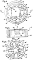
- An embodiment of the circuit which is suitable for use with the steel diaphragm 32 is shown in Figure 4.
- the IC 16 used for amplification and temperature compensation, is mounted on the diaphragm over the circuit and covers the central part of the circuit.
- the surface of the IC facing away from the diaphragm contains bond sites.
- the diaphragm is covered with an insulating coating (not shown) and then a conductive film.
- the film is scribed by trimming along lines 36 which define four resistors 38 and a plurality of conductive pathways 40.
- the pathways 40 along with wirebonds 42, connect the resistors to the IC, and with wirebonds 44 connect the resistors or the IC to the supply voltage V CC , ground or the output voltage V OUT to terminal pads on the terminal assembly 18. Additional pathways are wirebonded to bond sites on the IC for programming purposes. Because the pathways 40 cover wide areas, the bond sites 46 where the wirebonds 42 are attached on the wide pathways are readily chosen at places adjacent the fixed bond sites on the IC. Similarly, the bond pads 48 on the pathways for attaching the wirebonds 44 are readily selected places adjacent the terminal pads.
- the Figure 4 embodiment is shown in cross section in Figure 5.
- the IC is mounted over the boss 34 by an adhesive 49.
- the IC is larger than the boss so that peripheral portions overlie the flexible portion of the diaphragm; then the adhesive must be sufficiently soft or compliant to avoid interference to the diaphragm movement and to prevent harmful amounts of stress to the IC.
- a silicone adhesive formulated with a high coefficient of elasticity is suitable for this purpose.
- the IC is smaller than the boss 34 and lies entirely within the region defined by the boss. Since the region of the diaphragm containing the boss does not flex the IC will have a stable mount unaffected by pressure fluctuations.
- the diaphragm movement is very small and has no boss or no stress-free region. Because of the small movement the IC can still be mounted directly on the diaphragm with soft adhesive without adverse effects on either the IC or the sensor performance.
- the terminal assembly 18 comprises a nonconductive dome 50 with terminal blades 52 molded within the dome.
- the dome 50 has a cylindrical wall 54 surrounding the sensor 14 and seated on the base 10, and a top 56.
- an opening 58 is provided in the dome top 56 and wall 54 on one side of the terminal assembly.
- the opening forms a shortened wall portion defining a shelf 60 at its top.
- the terminal blades have outer ends 52 aligned with the diaphragm and extending from the top 56 substantially normal to and away from the diaphragm.
- An inner portion for each terminal embedded in the dome comprises a run 64 in the top 56 and a semi-cylindrical run 66 in the wall 54 which extends to the opening 58.
- the other end of the terminal is a terminal pad 68 situated on the shelf 60.
- the cover 20 partially shown in Figure 2, has a large diameter lower edge 74 nested between the terminal assembly 18 and the annular rib 26. Above the top dome 56 the cover reduces in diameter at a shoulder 76 and engages the walls 72 of protuberance 70 to enclose the dome opening 58. If desired, the shoulder seals against the protuberance to seal the diaphragm region from the outer environment.
- Figure 6 shows another embodiment of a pressure sensor which also has a diaphragm 32' supported by cylindrical wall 30' and having a central boss, not shown.
- An IC 16' shown in phantom lines is mounted at the center.
- the diaphragm is stainless steel coated with an insulating layer and a polysilicon layer covers at least part of the diaphragm area.
- Four piezo-resistive elements 38' are formed in the polysilicon.
- Gold conductive traces 40' formed on the silicon surface extend from bond pads 44' at the diaphragm edge to bond sites 46' near the edge of the IC for wirebonding to the IC.
- the traces 40' also extend to ends of the resistor elements 38' and some traces connect resistor elements to bond sites identified as S+ and S-.
- Four programming pads 47 are coupled by traces to bond sites 46' for connection to the IC. Only a few of the wire bonds 42' to the IC are shown.
- the pressure sensor is packaged in the same manner as shown in Figure 2 so that wire bonds will be made between the bond pads 44' and the corresponding terminal pads on the terminal assembly.
- the pressure sensor apparatus is simplified by directly mounting the IC on the pressure sensing diaphragm and making the electrical connections to the terminal assembly by wirebonding after assembling the terminal assembly on the base.
- the terminal assembly is compact and permits the final wirebond connection to be made after the assembly is installed.
- Intermediate circuits such as expensive flex circuits are avoided as well as pin and socket connections.
- the apparatus is readily adapted to automated assembly so that high costs of manual assembly are avoided.
- the size of the sensor apparatus is reduced by having fewer components to package.
Landscapes
- Physics & Mathematics (AREA)
- General Physics & Mathematics (AREA)
- Chemical & Material Sciences (AREA)
- Analytical Chemistry (AREA)
- Measuring Fluid Pressure (AREA)
- Details Of Connecting Devices For Male And Female Coupling (AREA)
- Wire Bonding (AREA)
Applications Claiming Priority (2)
| Application Number | Priority Date | Filing Date | Title |
|---|---|---|---|
| US591876 | 1996-01-25 | ||
| US08/591,876 US5629486A (en) | 1996-01-25 | 1996-01-25 | Pressure sensor apparatus with integrated circuit mounted thereon |
Publications (2)
| Publication Number | Publication Date |
|---|---|
| EP0786651A2 true EP0786651A2 (de) | 1997-07-30 |
| EP0786651A3 EP0786651A3 (de) | 1997-12-03 |
Family
ID=24368321
Family Applications (1)
| Application Number | Title | Priority Date | Filing Date |
|---|---|---|---|
| EP19960203678 Withdrawn EP0786651A3 (de) | 1996-01-25 | 1996-12-23 | Druckwandler mit integrierte Schaltung |
Country Status (3)
| Country | Link |
|---|---|
| US (1) | US5629486A (de) |
| EP (1) | EP0786651A3 (de) |
| JP (1) | JPH09251877A (de) |
Cited By (2)
| Publication number | Priority date | Publication date | Assignee | Title |
|---|---|---|---|---|
| WO2000019178A3 (de) * | 1998-09-29 | 2000-11-23 | Bosch Gmbh Robert | Druckgeber |
| WO2018144274A1 (en) * | 2017-02-06 | 2018-08-09 | Rosemount Inc. | Improved pressure transducer |
Families Citing this family (19)
| Publication number | Priority date | Publication date | Assignee | Title |
|---|---|---|---|---|
| DE69815801T2 (de) * | 1997-12-11 | 2004-05-19 | Nagano Keiki Co., Ltd. | Druckwandler |
| US5932809A (en) * | 1998-02-17 | 1999-08-03 | Delco Electronics Corporation | Sensor with silicon strain gage |
| US20020047304A1 (en) * | 2000-07-18 | 2002-04-25 | Marc Bolitho | Pressure sensor integrated onto sleeve of solenoid valve |
| US6427539B1 (en) * | 2000-07-31 | 2002-08-06 | Motorola, Inc. | Strain gauge |
| US6484589B1 (en) * | 2001-05-30 | 2002-11-26 | Senx Technology | Piezoelectric transducer assemblies and methods for their use |
| US6772509B2 (en) | 2002-01-28 | 2004-08-10 | Motorola, Inc. | Method of separating and handling a thin semiconductor die on a wafer |
| US6608370B1 (en) * | 2002-01-28 | 2003-08-19 | Motorola, Inc. | Semiconductor wafer having a thin die and tethers and methods of making the same |
| US6725514B2 (en) | 2002-05-31 | 2004-04-27 | Delphi Technologies, Inc. | Method of making thick film pressure and temperature sensors on a stainless steel diaphragm |
| IT1394791B1 (it) * | 2009-05-20 | 2012-07-13 | Metallux Sa | Sensore di pressione |
| DE102012204904B4 (de) * | 2012-03-27 | 2026-02-05 | Robert Bosch Gmbh | Sensoreinheit |
| US9310266B2 (en) * | 2013-05-08 | 2016-04-12 | Sensata Technologies, Inc. | Strain gauge pressure sensor |
| JP6228790B2 (ja) * | 2013-09-18 | 2017-11-08 | アルプス電気株式会社 | 圧力検知装置およびこれを使用した吸気圧測定装置 |
| DE102014216158A1 (de) * | 2014-02-17 | 2015-08-20 | Robert Bosch Gmbh | Anschlussvorrichtung für einen Drucksensor, Drucksensor und Verfahren zur Herstellung einer Anschlussvorrichtung |
| CN107290099B (zh) | 2016-04-11 | 2021-06-08 | 森萨塔科技公司 | 压力传感器、用于压力传感器的插塞件和制造插塞件的方法 |
| EP3236226B1 (de) | 2016-04-20 | 2019-07-24 | Sensata Technologies, Inc. | Verfahren zur herstellung eines drucksensors |
| US10545064B2 (en) | 2017-05-04 | 2020-01-28 | Sensata Technologies, Inc. | Integrated pressure and temperature sensor |
| US10323998B2 (en) | 2017-06-30 | 2019-06-18 | Sensata Technologies, Inc. | Fluid pressure sensor |
| US10724907B2 (en) | 2017-07-12 | 2020-07-28 | Sensata Technologies, Inc. | Pressure sensor element with glass barrier material configured for increased capacitive response |
| US10557770B2 (en) | 2017-09-14 | 2020-02-11 | Sensata Technologies, Inc. | Pressure sensor with improved strain gauge |
Family Cites Families (7)
| Publication number | Priority date | Publication date | Assignee | Title |
|---|---|---|---|---|
| US3341794A (en) * | 1965-07-26 | 1967-09-12 | Statham Instrument Inc | Transducers with substantially linear response characteristics |
| JPS57115873A (en) * | 1981-01-09 | 1982-07-19 | Hitachi Ltd | Semiconductor diaphragm type pressure sensor |
| US4993267A (en) * | 1988-04-08 | 1991-02-19 | General Electric Company | Electronic transducer |
| IT1223710B (it) * | 1988-07-21 | 1990-09-29 | Marelli Autronica | Trasduttore di altissima pressione in particolare per il rilevamento della pressione di un fluido idraulico |
| US5143888A (en) * | 1990-04-23 | 1992-09-01 | Phillips Petroleum Company | Group VIII catalyst supported on mixture of zinc aluminate and calcium aluminate |
| US5209122A (en) * | 1991-11-20 | 1993-05-11 | Delco Electronics Corporation | Pressurer sensor and method for assembly of same |
| US5257547A (en) * | 1991-11-26 | 1993-11-02 | Honeywell Inc. | Amplified pressure transducer |
-
1996
- 1996-01-25 US US08/591,876 patent/US5629486A/en not_active Expired - Lifetime
- 1996-12-23 EP EP19960203678 patent/EP0786651A3/de not_active Withdrawn
-
1997
- 1997-01-27 JP JP1221297A patent/JPH09251877A/ja active Pending
Non-Patent Citations (1)
| Title |
|---|
| None |
Cited By (2)
| Publication number | Priority date | Publication date | Assignee | Title |
|---|---|---|---|---|
| WO2000019178A3 (de) * | 1998-09-29 | 2000-11-23 | Bosch Gmbh Robert | Druckgeber |
| WO2018144274A1 (en) * | 2017-02-06 | 2018-08-09 | Rosemount Inc. | Improved pressure transducer |
Also Published As
| Publication number | Publication date |
|---|---|
| JPH09251877A (ja) | 1997-09-22 |
| US5629486A (en) | 1997-05-13 |
| EP0786651A3 (de) | 1997-12-03 |
Similar Documents
| Publication | Publication Date | Title |
|---|---|---|
| US5629486A (en) | Pressure sensor apparatus with integrated circuit mounted thereon | |
| EP0786650B1 (de) | Elektrische Anschlussvorrichtung | |
| US7412894B2 (en) | Pressure sensing device incorporating pressure sensing chip in resin case | |
| EP1686363B1 (de) | Kombinierter Druck- und Temperaturwandler | |
| JP2854896B2 (ja) | 圧力センサー | |
| US7370536B2 (en) | Pressure sensor device and pressure sensor cell thereof | |
| US4295117A (en) | Pressure sensor assembly | |
| US5086777A (en) | Small-sized disposable pressure transducer apparatus with a temperature compensating circuit disposed adjacent a passageway coupled with a catheter | |
| US5948989A (en) | Pressure sensor device | |
| KR101772197B1 (ko) | 온도압력진동 복합센서 구조체 | |
| US7559247B2 (en) | Pressure sensor with reduced size strain gauge mounting structure and manufacturing method of the same | |
| EP0614522B1 (de) | Druckwandler mit Verstärker | |
| CN1332190C (zh) | 压力传感器组件 | |
| WO2005057154A1 (en) | Isolated pressure transducer | |
| US6050146A (en) | Pressure detection apparatus | |
| US5174158A (en) | Resistive strain gauge pressure sensor | |
| US6997059B2 (en) | Pressure sensor | |
| US6313514B1 (en) | Pressure sensor component | |
| CN113108832B (zh) | 传感器 | |
| US5224384A (en) | Resistive strain gauge pressure sensor | |
| JP2002333377A (ja) | 圧力センサ | |
| JP2006194683A (ja) | 温度センサ一体型圧力センサ装置 | |
| JPH1038730A (ja) | 圧力センサ並びに圧力センサを用いた圧力検出装置 | |
| JP7252956B2 (ja) | 圧力センサ装置 | |
| JPH1114485A (ja) | 圧力センサ |
Legal Events
| Date | Code | Title | Description |
|---|---|---|---|
| PUAI | Public reference made under article 153(3) epc to a published international application that has entered the european phase |
Free format text: ORIGINAL CODE: 0009012 |
|
| AK | Designated contracting states |
Kind code of ref document: A2 Designated state(s): DE FR GB |
|
| PUAL | Search report despatched |
Free format text: ORIGINAL CODE: 0009013 |
|
| AK | Designated contracting states |
Kind code of ref document: A3 Designated state(s): DE FR GB |
|
| 17P | Request for examination filed |
Effective date: 19980603 |
|
| RAP1 | Party data changed (applicant data changed or rights of an application transferred) |
Owner name: DELPHI TECHNOLOGIES, INC. |
|
| 17Q | First examination report despatched |
Effective date: 20001212 |
|
| STAA | Information on the status of an ep patent application or granted ep patent |
Free format text: STATUS: THE APPLICATION IS DEEMED TO BE WITHDRAWN |
|
| 18D | Application deemed to be withdrawn |
Effective date: 20010424 |