EP0786741B1 - Verfahren und Vorrichtung zur Binärkodierung von Bilddaten - Google Patents
Verfahren und Vorrichtung zur Binärkodierung von Bilddaten Download PDFInfo
- Publication number
- EP0786741B1 EP0786741B1 EP97101145A EP97101145A EP0786741B1 EP 0786741 B1 EP0786741 B1 EP 0786741B1 EP 97101145 A EP97101145 A EP 97101145A EP 97101145 A EP97101145 A EP 97101145A EP 0786741 B1 EP0786741 B1 EP 0786741B1
- Authority
- EP
- European Patent Office
- Prior art keywords
- image data
- error
- pixel
- data
- valued image
- Prior art date
- Legal status (The legal status is an assumption and is not a legal conclusion. Google has not performed a legal analysis and makes no representation as to the accuracy of the status listed.)
- Expired - Lifetime
Links
Images








Classifications
-
- G—PHYSICS
- G06—COMPUTING OR CALCULATING; COUNTING
- G06T—IMAGE DATA PROCESSING OR GENERATION, IN GENERAL
- G06T9/00—Image coding
- G06T9/004—Predictors, e.g. intraframe, interframe coding
-
- H—ELECTRICITY
- H04—ELECTRIC COMMUNICATION TECHNIQUE
- H04N—PICTORIAL COMMUNICATION, e.g. TELEVISION
- H04N1/00—Scanning, transmission or reproduction of documents or the like, e.g. facsimile transmission; Details thereof
- H04N1/40—Picture signal circuits
- H04N1/405—Halftoning, i.e. converting the picture signal of a continuous-tone original into a corresponding signal showing only two levels
- H04N1/4051—Halftoning, i.e. converting the picture signal of a continuous-tone original into a corresponding signal showing only two levels producing a dispersed dots halftone pattern, the dots having substantially the same size
- H04N1/4052—Halftoning, i.e. converting the picture signal of a continuous-tone original into a corresponding signal showing only two levels producing a dispersed dots halftone pattern, the dots having substantially the same size by error diffusion, i.e. transferring the binarising error to neighbouring dot decisions
- H04N1/4053—Halftoning, i.e. converting the picture signal of a continuous-tone original into a corresponding signal showing only two levels producing a dispersed dots halftone pattern, the dots having substantially the same size by error diffusion, i.e. transferring the binarising error to neighbouring dot decisions with threshold modulated relative to input image data or vice versa
Definitions
- the present invention relates to a method of binary coding multi-valued image data and also to an apparatus for the same.
- An error diffusion method has widely been used for binary coding multi-valued image data, in order to record multi-tone images in a simulating manner with a binary recording device, such as an ink jet printer.
- Fig. 9 is a block diagram illustrating a conventional image data binary device for which the error diffusion method is applied.
- the image data binary device includes an error memory 120, an adder 122, a comparator 124, a subtracter 126, a bit converter 128, and an error distribution circuit 130.
- Multi-valued image data has a dynamic range of 0 to 255.
- the thick lines represent multi-bit data lines including symbol bit, integral bits, and decimal bits.
- the error diffusion method distributes an error, which arises as a difference between image data for a specific pixel before and after binary coding, into pixels in the vicinity of the specific pixel at a predetermined ratio.
- Figs. 10(a) and 10(b) show the principle of the error diffusion method.
- the procedure of binary coding pixels 232 included in an image 230 is carried out in an order specified by an arrow 231.
- the multi-valued image data is first corrected by adding error data accumulated for the pixel of interest P to the multi-valued image data.
- X denotes a value of multi-valued image data regarding the pixel of interest P
- ⁇ e p represents error data accumulated for the pixel of interest P
- X' X + ⁇ e P
- the error data accumulated for the pixel of interest P represents the total of errors distributed to the pixel of interest P from the peripheral pixels that have already undergone the binary coding as discussed later.
- the value X' of corrected multi-valued image data is then compared with a predetermined threshold value (for example, 128), so that the multi-valued image data regarding the pixel of interest P is binary coded.
- a predetermined threshold value for example, 128,
- Y (0 or 255) represents a value of binary-coded image data
- the value of the error 'e' is subsequently distributed at a predetermined ratio (ratio of error distribution) into pixels that are located in the vicinity of the pixel of interest P and have not yet undergone the binary coding.
- a predetermined ratio ratio of error distribution
- the value of the error 'e' is distributed into four pixels in the vicinity of the pixel of interest P; that is, pixels A, B, C, and D located on the immediate right of, on the lower right of, immediately below, and on the lower left of the pixel of interest P as shown in Fig. 10(b).
- the ratio of error distribution applied is 7/16 to the pixel A, 1/16 to the pixel B, 5/16 to the pixel C, and 3/16 to the pixel D as shown below:
- the error distributed into the pixels prior to the binary coding is accumulated as the error data for each pixel in the error memory 120.
- the adder 122 receives multi-valued image data regarding the pixel of interest P.
- the error data ⁇ e P accumulated for the pixel of interest P is read from the error memory 120 and inputted into the adder 122.
- the adder 122 adds the error data to the input multi-valued image data to correct the multi-valued image data.
- the comparator 124 receives the corrected multi-valued image data from the adder 122, compares the corrected multi-valued image data with a separately input reference value, and outputs one-bit data or binary image data based on the results of comparison. This process binary codes the corrected multi-valued image data sent from the adder 122.
- the bit converter 128 converts the one-bit binary image data outputted from the comparator 124 to 8-bit binary image data (0 or 255).
- the subtracter 126 receives the corrected multi-valued image data (image data before the binary coding) outputted from the adder 122 and the image data (image data after the binary coding) outputted from the bit converter 128, subtracts the image data after the binary coding from the image data before the binary coding, and calculates the error 'e' arising in the process of binary coding the multi-valued image data for the pixel of interest P.
- the error distribution circuit 130 distributes the error 'e' obtained by the subtracter 126 into the pixels A, B, C, and D, which are located in the vicinity of the pixel of interest P and have not yet undergone the binary coding, at a predetermined distribution ratio as discussed above with the drawing of Fig. 10.
- the error distribution circuit 130 multiplies the error 'e' by predetermined coefficients corresponding to the pixels A, B, C, and D, for example, those shown in Equations (3) given above, and adds the results of operations e A , e B , e C , and e D to error data ⁇ e A , ⁇ e B , ⁇ e C , and ⁇ e D for the pixels A, B, C, and D accumulated in the error memory 120, so as to update the values of the respective error data ⁇ e A , ⁇ e B , ⁇ e C , and ⁇ e D .
- the image data binary device shown in Fig. 9 utilizes the error diffusion method to binary code the multi-valued image data. This allows the image to be expressed in quasi multi-tones even when the multi-valued image data has been binary coded.
- the pixels having the value '1' as the binary-coded image data are arranged as dotted lines in the image.
- the pixels having the value '0' as the binary-coded image data are arranged as dotted lines in the image. These dotted lines significantly deteriorate the quality of picture.
- the tone value of the multi-valued image data corresponds to the density in the resulting recorder image. This means that the input of the multi-valued image data having a relatively low tone value gives a printed image of a relatively low density, whereas the input of the multi-valued image data having a relatively high tone value gives a printed image of a relatively high density.
- Figs. 11, 12, 13, and 14 show the printing results with a printer when the image data binary device of Fig. 9 is applied.
- Fig. 11 shows the printing result for a low-density area of 0% to 10%
- Fig. 12 shows the printing result for a high-density area of 90% to 100%
- Fig. 13 shows the printing result for a low-density area of 0% to 15%
- Fig. 14 shows the printing result for a high-density area of 85% to 100%.
- the density continuously varies in the respective ranges along the width of the image.
- the binary coding process in these examples is carried out in the manner shown in Fig. 10(a) ; that is, starting from the upper. left corner of the image and scanning from the left to the right one line by one line. This is also applied to the binary coding process in the examples below.
- Fig. 15 shows the printing result specifically selected for the density of 3% among the low-density area of Fig. 11;
- Fig. 16 shows the printing result specifically selected for the density of 97% among the high-density area of Fig. 12;
- Fig. 17 shows the printing result specifically selected for the density of 1% among the low-density area of Fig. 11;
- Fig. 18 shows the printing result specifically selected for the density of 99% among the high-density area of Fig. 12.
- the whole image has a homogeneous density.
- black dots that is, the pixels having the value '1'
- white dots that is, the pixels having the value '0'
- the black dots or the white dots are not homogeneously dispersed and such dotted lines remarkably deteriorate the quality of picture.
- Fig. 19 shows the printing result with a printer for the whole density range of 0% to 100% when the image data binary device of Fig. 57 is applied.
- the density continuously varies from the left to the right in the range of 0% to 100% along the width of the image.
- Fig. 20 shows the printing result with a printer for an intermediate-density range of 15% to 85% when the image data binary device of Fig. 9 is applied.
- the density continuously varies in the above range along the width of the image.
- textures are often observed in the intermediate-density area of 15% to 85% in the image obtained as the binary-coded image data as shown in Figs. 19 and 20, thereby deteriorating the quality of picture.
- the textures herein denote patterns having some regularity and included in a planar distribution of depth.
- the proposed method to prevent textures in the intermediate-density area adds dither data to the input image data prior to binary coding and varies the ratio of error distribution for distributing the value of the error 'e' at random according to random numbers.
- the known technique disclosed in the above paper depresses the occurrence of textures irrespective of the tone value of the input image data prior to binary coding.
- the processing is thus carried out even for the image data having a relatively low tone value or a relatively high tone value, wherein no significant textures are originally generated. This significantly deteriorates the quality of picture in the low-density area and in the high-density area.
- Another proposed method removes the textures observed in the intermediate-density area by adding a random number to a reference value used in the binary-coding means. This method, however, can not remove the textures observed in the low-density area or the high-density area.
- the textures observed in the low-density area or the high-density area can be improved by distributing the error, which arises in the process of binary coding the multi-valued image data for the pixel of interest, into a larger number of pixels which have not yet undergone the binary coding.
- This method undesirably increases the scale of the hardware and lengthens the required processing time for binary coding.
- EP 0 531 170 A2 relates to a process, where an error term between non-coded and coded optical density values is determined and a preselected fraction of the error term on a weighted basis is distributed to a predetermined set of neighboring pixels.
- Other methods are described in the introductory part of said document, and error distribution schemes are addressed, but it is generally seen as a disadvantage, that procedures given there calculate errors that include all errors previously made.
- One of the error distribution schemes mentioned is described in US 5 313 287 in further detail in relation to figure 5A thereof, namely the adaptive algorithm developed by Floyd and Steinberg.
- the adaptive algorithm of Floyd and Steinberg is detailed in an article of Robert W. Floyd and Louis Steinberg, "An Adaptive Algorithm for Spatial Grayscale", XP 000616372: Proc SID, vol. 17, no. 2, April 1976, pp. 75 - 77.
- the error distribution method disclosed in EP 0 341 984 A2 is configured such that a surplus of an error generated when the error is dispersed with weighing in the error diffusion method is added to input image data of a next picture element.
- PCT/US90/07037 is concerned with electronic screening where a first screen matrix having a plurality of sub-elements having a threshold value pattern which grows around a target pixel is generated, wherein a second screen matrix having a plurality of sub-elements having a threshold value pattern which grows in a high spatial frequency is generated and then either the first matrix or the second matrix is selected to compare to an image signal value based on the tonal value of the picture element to achieve at optimum representation.
- the object of the present invention is thus to provide an improved method of binary coding multi-valued image data without damaging the quality of picture as well as an improved apparatus for the same.
- a method of binary coding multi-valued image data for each pixel includes the steps of: (a) adding first error data accumulated for a target pixel of binary coding and at least part of second error data accumulated for a specific pixel which is located in the vicinity of the target pixel and which is to be processed by binary coding after the target pixel, so as to correct the multi-valued image data; (b) comparing the corrected multi-valued image data with a predetermined reference value and binary coding the corrected multi-valued image data based on the result of the comparison; (c) obtaining an error that is difference between the corrected multi-valued image data and the binary-coded image data for the target pixel; (d) distributing the error obtained for the target pixel into pixels which are to be processed by binary coding after the target pixel; (e) accumulating the distributed errors as error data for each pixel; and (f) repeating the steps (a) through (e) for successive the target pixels of said multi-valued image data.
- the multi-valued image data for the target pixel is corrected by adding not only the error data accumulated for the target pixel but the error data accumulated for a specific pixel which is located in the vicinity of the target pixel and which is to be processed by binary coding after the target pixel. This remarkably improves the quality of the image expressed by the binary-coded image data.
- an apparatus for binary coding multi-valued image data for each pixel which apparatus includes: correction means for adding first error data accumulated for a target pixel of binary coding and at least part of second error data accumulated for a specific pixel which is located in the vicinity of said target pixel and which is to be processed by binary coding after said target pixel, so as to correct the multi-valued image data; updating means for updating said first error data and said second error data according to a specified rule; binary coding means for comparing the corrected multi-valued image data of the target pixel with a predetermined reference value and binary coding the corrected multi-valued image data based on the result of the comparison; error calculation means for obtaining an error that is difference between the corrected multi-valued image data and the binary-coded image data for said target pixel; error distribution means for distributing the error obtained for said target pixel into pixels which are to be processed by binary coding after said target pixel; and error accumulation means for accumulating for each pixel the
- the multi-valued image data for the target pixel is corrected by adding not only the error data accumulated for the target pixel but the error data accumulated for a specific pixel which is located in the vicinity of said target pixel and which is to be processed by binary coding after said target pixel. This remarkably improves the quality of the image expressed by the binary-coded image data.
- Fig. 1 is a block diagram illustrating an image data binary device as an embodiment according to the present invention.
- the image data binary device of the embodiment includes an error memory 20, a comparator 24, a subtracter 26, a bit converter 28, an error distribution circuit 30, a data correction circuit 34, and an error updating circuit 36.
- Fig. 2 is a flowchart showing an image data binary coding routine executed by the image data binary device of Fig. 1.
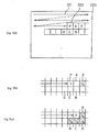
- FIGs. 3(a) through 3(c) show an error diffusion process applied for the third embodiment.
- the procedure of binary coding pixels 222 included in an image 220 is carried out in an order specified by an arrow 221.
- the multi-valued image data is corrected by adding error data ⁇ e P accumulated for the pixel of interest P and part of the error data accumulated for a pixel that is located in the vicinity of the pixel of interest P and has not yet undergone the binary coding process to the multi-valued image data for the pixel of interest P.
- a pixel E is selected as a pixel that is located in the vicinity of the pixel of interest P and has not yet undergone the binary coding process, as shown in Fig. 3(b).
- the whole value of error data ⁇ e P accumulated for the pixel of interest P and one eighth the value of error data ⁇ e E accumulated for the pixel E are added to the multi-valued image data regarding the pixel of interest P.
- the value X' ' of corrected multi-valued image data is then compared with a predetermined threshold value (for example, 128), so that the multi-valued image data regarding the pixel of interest P is binary coded.
- a predetermined threshold value for example, 128,
- the value of the error 'e' is then distributed at a predetermined ratio (ratio of error distribution) to pixels A, B, C, and D that are located in the vicinity of the pixel of interest P and have not yet undergone the binary coding process as shown in Fig. 3(c).
- the errors distributed to the pixels prior to the binary coding are accumulated as error data for each pixel in the error memory 20.
- the data correction circuit 34 receives multi-valued image data regarding the pixel P.
- the multi-valued image data is, for example, 8-bit data and may take any value of 0 to 255 as the tone value.
- the error data ⁇ e P distributed from the binary-coded peripheral pixels and accumulated for the pixel of interest P and the error data ⁇ e E distributed from the binary-coded peripheral pixels and accumulated for the pixel E are read from the error memory 20 and also inputted into the data correction circuit 34.
- the data correction circuit 34 carries out a correction process at step S50. Namely, the data correction circuit 34 corrects the input multi-valued image data for the pixel of interest P by adding the error data ⁇ e P accumulated for the pixel of interest P and part of the error data ⁇ e E accumulated for the pixel E, that is, 1/8 ⁇ e E , to the multi-valued image data.
- the error updating circuit 36 updates the error data ⁇ e P and ⁇ e E stored in the error memory 20 respectively to 0 and 7/8 ⁇ e E according to Equations (8) given above at step S51.
- the comparator 24 receives the corrected multi-valued image data from the data correction circuit 34, compares the corrected multi-valued image data with a separately input reference value, and outputs one-bit data or binary image data based on the results of comparison.
- the value '128' that is an intermediate value between the value '0' and the value 255' is used as the reference value.
- the comparator 24 outputs the value '1' when the value of the corrected multi-valued image data outputted from the data correction circuit 34 is equal to or greater than the reference value '128'.
- the comparator outputs the value '0', on the other hand, when the value of the corrected multi-valued image data is smaller than the reference value '128'.
- This process binary codes the corrected multi-valued image data outputted from the data correction circuit 34.
- the bit converter 28 converts the one-bit binary image data outputted from the comparator 24 to 8-bit binary image data.
- the bit converter 28 When the value of the image data outputted from the comparator 24 is equal to '0', the bit converter 28 outputs data of the value '0' as the 8-bit image data.
- the bit converter 28 When the value of the image data outputted from the comparator 24 is equal to '1', on the contrary, the bit converter 28 outputs data of the value '255' as the 8-bit image data.
- the subtracter 26 receives the corrected multi-valued image data (image data before the binary coding) outputted from the data correction circuit 34 and the image data (image data after the binary coding) outputted from the bit converter 28, subtracts the image data after the binary coding from the image data before the binary coding, and calculates the error 'e' arising in the process of binary coding the multi-valued image data for the pixel of interest P.
- the error distribution circuit 30 distributes the error 'e' obtained by the subtracter 26 into the pixels A, B, C, and D, which are located in the vicinity of the pixel of interest P and have not yet undergone the binary coding, as discussed in Fig. 3(c).
- An error accumulation process executed at step S58 then accumulates the distributed errors into the error memory 20 as error data for each pixel.
- the error distribution circuit 30 multiplies the error 'e' by predetermined coefficients corresponding to the pixels A, B, C, and D, for example, those shown in Equations (3) given above, and adds the results of operations e A , e B , e C , and e D to error data ⁇ e A , ⁇ e B , ⁇ e C , and ⁇ e D for the pixels A, B, C, and D accumulated in the error memory 20, so as to update the values of the respective error data ⁇ e A , ⁇ e B , ⁇ e C , and ⁇ e D .
- the target of the binary coding shifts from the pixel P to the next pixel A and the same processes are repeated for the next pixel of interest A.
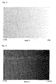
- Figs. 4 and 5 respectively show the results of printing with a printer when the image data binary device of Fig. 1 is applied.
- Fig. 4 shows the printing result for a low-density area of 0% to 15%
- Fig. 5 shows the printing result for a high-density area of 85% to 100%.
- the density continuously varies in the respective ranges along the width of the image.
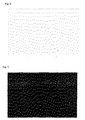
- Fig. 6 shows the printing result specifically selected for the density of 1% among the low-density area of Fig. 4, and Fig. 7 shows the printing result specifically selected for the density of 99% among the high-density area of Fig. 5.
- the structure of the embodiment enables the black dots and white dots to be arranged in a substantially homogeneous manner, thus remarkably improving the quality of picture.
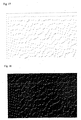
- Fig. 8 shows the printing result with a printer for an intermediate-density area of 15% to 85% when the image data binary device of Fig. 1 is applied. There is no significant difference between the printing result of Fig. 8 by the method of the third embodiment and that of Fig. 20 by the conventional process in this intermediate-density area.
- the multi-valued image data for the pixel of interest P is corrected by adding a fixed fraction (1/8 in the embodiment) of the error data ⁇ e E accumulated for the pixel E to the multi-valued image data.
- the fraction (ratio of addition) can be set suitably corresponding to the multi-valued image data regarding the pixel of interest. This further improves the quality of the binary-coded image and shortens the required time for binary coding.
Landscapes
- Engineering & Computer Science (AREA)
- Multimedia (AREA)
- Signal Processing (AREA)
- Physics & Mathematics (AREA)
- General Physics & Mathematics (AREA)
- Theoretical Computer Science (AREA)
- Facsimile Image Signal Circuits (AREA)
- Image Processing (AREA)
Claims (4)
- Verfahren zum Binärcodieren mehrwertiger Bilddaten für jedes Bildelement, wobei das Verfahren die Schritte aufweist:(a) Addieren (S50) erster Fehlerdaten (∑eP), die für Ziel-Bildelement (P) der Binärcodierung gesammelt worden sind, und wenigstens einem Teil zweiter Fehlerdaten (∑eE), die für ein bestimmtes Bildelement (E) gesammelt worden sind, welches sich in der Nachbarschaft des Ziel-Bildelementes befindet und welches durch Binärcodieren nach dem Ziel-Bildelement verarbeitet werden soll, um so die mehrwertigen Bilddaten (X) zu korrigieren (34);(b) Vergleichen (S52) der korrigierten mehrwertigen Bilddaten mit einem vorbestimmten Referenzwert und Binärcodieren (24) der korrigierten mehrwertigen Bilddaten (X") basierend auf dem Ergebnis des Vergleichs;(c) Erhalten (S54) eines Fehlers, der die Differenz zwischen den korrigierten mehrwertigen Bilddaten (X") und den binärcodierten Bilddaten für das Ziel-Bildelement ist;(d) Verteilen (S56) des Fehlers, der für das Ziel-Bildelement (P) erhalten worden ist, in Bildelemente (A-D), die durch Binärcodieren nach dem Ziel-Bildelement verarbeitet werden sollen;(e) Sammeln (S58) der verteilten Fehler als Fehlerdaten für jedes Bildelement; und(f) Wiederholen der Schritte (a) bis (e) für aufeinander folgende Ziel-Bildelemente der mehrwertigen Bilddaten.
- Verfahren nach Anspruch 1, bei dem der Schritt (a) den Schritt des Aktualisierens (S51) der ersten Fehlerdaten (∑eP) und der zweiten Fehlerdaten (∑eE) entsprechend einer festgelegten Regel nach dem Addieren aufweist.
- Verfahren nach Anspruch 1, bei dem der Schritt (a) die Schritte aufweist:(a-1) Multiplizieren der zweiten Fehlerdaten mit einem Koeffizienten K (0≤K≤1), der abhängig von den mehrwertigen Bilddaten für das Ziel-Bildelement festgelegt wird, um Produktdaten zu erhalten; und(a-2) Addieren der ersten Fehlerdaten und der Produktdaten zu den mehrwertigen Bilddaten für das Ziel-Bildelement, um die mehrwertigen Bilddaten zu korrigieren.
- Vorrichtung zum Binärcodieren mehrwertiger Bilddaten für jedes Bildelement, wobei die Vorrichtung aufweist:eine Korrektureinrichtung (34) zum Addieren erster Fehlerdaten (∑eP), die für ein Ziel-Bildelement (P) zum Binärcodieren gesammelt worden sind, und wenigstens einem Teil zweiter Fehlerdaten (∑eE), die für ein bestimmtes Bildelement (E) gesammelt worden sind, das sich in der Nachbarschaft des Ziel-Bildelementes befindet, und das durch Binärcodieren nach dem Ziel-Bildelement verarbeitet werden soll, um so die mehrwertigen Bilddaten (X) zu korrigieren;eine Aktualisierungseinrichtung (36) zum Aktualisieren der ersten Fehlerdaten und der zweiten Fehlerdaten gemäß einer festgelegten Regel;eine Binärcodiereinrichtung (24) zum Vergleichen der mehrwertigen Bilddaten des Ziel-Bildelementes mit einem vorbestimmten Referenzwert und Binärcodieren der korrigierten mehrwertigen Bilddaten (X") basierend auf dem Ergebnis des Vergleichs;eine Fehlerberechnungseinrichtung (26) zum Erhalten eines Fehlers, der die Differenz zwischen den korrigierten mehrwertigen Bilddaten (X") und den binärcodierten Bilddaten für das Ziel-Bildelement ist;eine Fehlerverteilungseinrichtung (30,) zum Verteilen des Fehlers, der für das Ziel-Bildelement (P) erhalten worden ist, auf Bildelemente (A-D), die durch Binärcodieren nach dem Ziel-Bildelement verarbeitet werde sollen; undeine Fehlersammeleinrichtung (30, 20) zum Sammeln, für jedes Bildelement, der verteilten Fehler als deren Fehlerdaten.
Applications Claiming Priority (12)
| Application Number | Priority Date | Filing Date | Title |
|---|---|---|---|
| JP3263196 | 1996-01-25 | ||
| JP8032631A JPH09205545A (ja) | 1996-01-25 | 1996-01-25 | 画像データ2値化方法及び装置 |
| JP32631/96 | 1996-01-25 | ||
| JP8038904A JPH09214760A (ja) | 1996-01-31 | 1996-01-31 | 画像データ2値化装置 |
| JP3890396 | 1996-01-31 | ||
| JP38903/96 | 1996-01-31 | ||
| JP3890496 | 1996-01-31 | ||
| JP38904/96 | 1996-01-31 | ||
| JP8038903A JPH09214759A (ja) | 1996-01-31 | 1996-01-31 | 画像データ2値化方法及び装置 |
| JP09623096A JP3574711B2 (ja) | 1996-03-25 | 1996-03-25 | 画像データ2値化方法及び装置 |
| JP96230/96 | 1996-03-25 | ||
| JP9623096 | 1996-03-25 |
Publications (3)
| Publication Number | Publication Date |
|---|---|
| EP0786741A2 EP0786741A2 (de) | 1997-07-30 |
| EP0786741A3 EP0786741A3 (de) | 1998-11-11 |
| EP0786741B1 true EP0786741B1 (de) | 2004-07-28 |
Family
ID=27459654
Family Applications (1)
| Application Number | Title | Priority Date | Filing Date |
|---|---|---|---|
| EP97101145A Expired - Lifetime EP0786741B1 (de) | 1996-01-25 | 1997-01-24 | Verfahren und Vorrichtung zur Binärkodierung von Bilddaten |
Country Status (3)
| Country | Link |
|---|---|
| US (1) | US5911009A (de) |
| EP (1) | EP0786741B1 (de) |
| DE (1) | DE69729965D1 (de) |
Families Citing this family (8)
| Publication number | Priority date | Publication date | Assignee | Title |
|---|---|---|---|---|
| JP3711707B2 (ja) * | 1997-08-07 | 2005-11-02 | ブラザー工業株式会社 | 画像2値化方法、画像2値化装置および記録媒体 |
| US6178009B1 (en) * | 1997-11-17 | 2001-01-23 | Canon Kabushiki Kaisha | Printing with multiple different black inks |
| US6172768B1 (en) * | 1998-02-05 | 2001-01-09 | Canon Kabushiki Kaisha | Halftoning with changeable error diffusion weights |
| US6731404B1 (en) * | 1999-11-03 | 2004-05-04 | Xerox Corporation | Halftone and error diffusion rendering circuits |
| JP4335467B2 (ja) * | 2000-03-07 | 2009-09-30 | セイコーインスツル株式会社 | 濃淡画像の階調再現方法および装置 |
| US20050050122A1 (en) * | 2003-09-02 | 2005-03-03 | Andreas Blumenthal | Object-oriented pseudo-random number generator interface |
| US7328228B2 (en) * | 2003-09-02 | 2008-02-05 | Sap Aktiengesellschaft | Mapping pseudo-random numbers to predefined number ranges |
| KR102792398B1 (ko) * | 2019-06-17 | 2025-04-10 | 한국전자통신연구원 | 난수 생성 장치 및 이의 동작 방법 |
Family Cites Families (9)
| Publication number | Priority date | Publication date | Assignee | Title |
|---|---|---|---|---|
| US4969052A (en) * | 1988-05-11 | 1990-11-06 | Canon Kabushiki Kaisha | Image processing method and apparatus |
| WO1991009489A2 (en) * | 1989-12-14 | 1991-06-27 | Eastman Kodak Company | Mixed matrix image processing for rendering halftone images with variable dot sizes |
| JP2500834B2 (ja) * | 1991-09-05 | 1996-05-29 | ゼロックス コーポレイション | 画素値の量子化方法及び装置 |
| US5313287A (en) * | 1993-04-30 | 1994-05-17 | Hewlett-Packard Company | Imposed weight matrix error diffusion halftoning of image data |
| JPH07114637A (ja) * | 1993-10-15 | 1995-05-02 | Riso Kagaku Corp | 画像処理装置 |
| JP3240803B2 (ja) * | 1994-02-14 | 2001-12-25 | セイコーエプソン株式会社 | 画像処理装置および画像処理方法 |
| JP3603906B2 (ja) * | 1994-04-15 | 2004-12-22 | 富士写真フイルム株式会社 | 画像信号2値化処理装置および方法 |
| JPH07307866A (ja) * | 1994-05-10 | 1995-11-21 | Fuji Photo Film Co Ltd | 画像信号2値化処理装置および方法 |
| US6427030B1 (en) * | 1994-08-03 | 2002-07-30 | Xerox Corporation | Method and system for image conversion utilizing dynamic error diffusion |
-
1997
- 1997-01-22 US US08/787,587 patent/US5911009A/en not_active Expired - Fee Related
- 1997-01-24 EP EP97101145A patent/EP0786741B1/de not_active Expired - Lifetime
- 1997-01-24 DE DE69729965T patent/DE69729965D1/de not_active Expired - Lifetime
Also Published As
| Publication number | Publication date |
|---|---|
| DE69729965D1 (de) | 2004-09-02 |
| US5911009A (en) | 1999-06-08 |
| EP0786741A2 (de) | 1997-07-30 |
| EP0786741A3 (de) | 1998-11-11 |
Similar Documents
| Publication | Publication Date | Title |
|---|---|---|
| EP0659012B1 (de) | Verfahren zur Quantisierung von Grautonbilddaten mit erweitertem Verteilungssatz | |
| EP1073258B1 (de) | Verringerung der Verschiebung von Fehlerdiffusionsmustern durch programmierbare Schwellenstörung | |
| US5394250A (en) | Image processing capable of handling multi-level image data without deterioration of image quality in highlight areas | |
| KR960014303B1 (ko) | 화상 처리 장치 | |
| EP0938064A2 (de) | Fehlerdiffusionsbildverarbeitungsgerät und Verfahren | |
| JP2974363B2 (ja) | 画像処理装置 | |
| US5208684A (en) | Half-tone image processing system | |
| JP3973734B2 (ja) | 電子イメージ処理システム及び処理方法 | |
| JPH07288689A (ja) | 画像信号2値化処理装置および方法 | |
| US20040010633A1 (en) | Method and apparatus for image processing | |
| EP0626780B1 (de) | Bildverarbeitungsverfahren und -gerät | |
| US5436736A (en) | Image processing apparatus | |
| US6369912B1 (en) | Image processing apparatus capable of applying line component to image | |
| US5911009A (en) | Method and apparatus for binary coding of image data including adding error accumulated for a target pixel and a pixel in the vicinity to be later coded | |
| US6181827B1 (en) | Image processing method and apparatus | |
| EP0604759B1 (de) | Verfahren und Apparat zur Verarbeitung digitaler Bilddaten | |
| US5825509A (en) | Image processing device with error-diffusion quantization function | |
| JP3124605B2 (ja) | 画像処理装置 | |
| JP2000270210A (ja) | 画像処理装置 | |
| JP3124589B2 (ja) | 画像処理装置 | |
| JP2860039B2 (ja) | 擬似中間調画像縮小装置 | |
| JPH0318177A (ja) | 画像処理装置 | |
| JP3167676B2 (ja) | 画像処理装置 | |
| JP2898322B2 (ja) | ディザ画像の中間調推定方式 | |
| JP3124604B2 (ja) | 画像処理装置 |
Legal Events
| Date | Code | Title | Description |
|---|---|---|---|
| PUAI | Public reference made under article 153(3) epc to a published international application that has entered the european phase |
Free format text: ORIGINAL CODE: 0009012 |
|
| AK | Designated contracting states |
Kind code of ref document: A2 Designated state(s): DE FR GB |
|
| RHK1 | Main classification (correction) |
Ipc: H04N 1/405 |
|
| PUAL | Search report despatched |
Free format text: ORIGINAL CODE: 0009013 |
|
| AK | Designated contracting states |
Kind code of ref document: A3 Designated state(s): DE FR GB |
|
| 17P | Request for examination filed |
Effective date: 19990315 |
|
| 17Q | First examination report despatched |
Effective date: 20030521 |
|
| GRAP | Despatch of communication of intention to grant a patent |
Free format text: ORIGINAL CODE: EPIDOSNIGR1 |
|
| GRAS | Grant fee paid |
Free format text: ORIGINAL CODE: EPIDOSNIGR3 |
|
| GRAA | (expected) grant |
Free format text: ORIGINAL CODE: 0009210 |
|
| AK | Designated contracting states |
Kind code of ref document: B1 Designated state(s): DE FR GB |
|
| PG25 | Lapsed in a contracting state [announced via postgrant information from national office to epo] |
Ref country code: FR Free format text: LAPSE BECAUSE OF FAILURE TO SUBMIT A TRANSLATION OF THE DESCRIPTION OR TO PAY THE FEE WITHIN THE PRESCRIBED TIME-LIMIT Effective date: 20040728 |
|
| REG | Reference to a national code |
Ref country code: GB Ref legal event code: FG4D |
|
| REF | Corresponds to: |
Ref document number: 69729965 Country of ref document: DE Date of ref document: 20040902 Kind code of ref document: P |
|
| PG25 | Lapsed in a contracting state [announced via postgrant information from national office to epo] |
Ref country code: DE Free format text: LAPSE BECAUSE OF FAILURE TO SUBMIT A TRANSLATION OF THE DESCRIPTION OR TO PAY THE FEE WITHIN THE PRESCRIBED TIME-LIMIT Effective date: 20041029 |
|
| PGFP | Annual fee paid to national office [announced via postgrant information from national office to epo] |
Ref country code: FR Payment date: 20050110 Year of fee payment: 9 |
|
| PGFP | Annual fee paid to national office [announced via postgrant information from national office to epo] |
Ref country code: DE Payment date: 20050120 Year of fee payment: 9 |
|
| PLBE | No opposition filed within time limit |
Free format text: ORIGINAL CODE: 0009261 |
|
| STAA | Information on the status of an ep patent application or granted ep patent |
Free format text: STATUS: NO OPPOSITION FILED WITHIN TIME LIMIT |
|
| 26N | No opposition filed |
Effective date: 20050429 |
|
| EN | Fr: translation not filed | ||
| PGFP | Annual fee paid to national office [announced via postgrant information from national office to epo] |
Ref country code: GB Payment date: 20080123 Year of fee payment: 12 |
|
| GBPC | Gb: european patent ceased through non-payment of renewal fee |
Effective date: 20090124 |
|
| PG25 | Lapsed in a contracting state [announced via postgrant information from national office to epo] |
Ref country code: GB Free format text: LAPSE BECAUSE OF NON-PAYMENT OF DUE FEES Effective date: 20090124 |