EP0786877B1 - Verfahren und Anordnung zum Inline-Regenerieren eines übertragenen Wellenlängenmultiplexsignals durch synchrone Modulation und optisches Übertragungssystem welches dieses Verfahren benutzt - Google Patents
Verfahren und Anordnung zum Inline-Regenerieren eines übertragenen Wellenlängenmultiplexsignals durch synchrone Modulation und optisches Übertragungssystem welches dieses Verfahren benutzt Download PDFInfo
- Publication number
- EP0786877B1 EP0786877B1 EP97400106A EP97400106A EP0786877B1 EP 0786877 B1 EP0786877 B1 EP 0786877B1 EP 97400106 A EP97400106 A EP 97400106A EP 97400106 A EP97400106 A EP 97400106A EP 0786877 B1 EP0786877 B1 EP 0786877B1
- Authority
- EP
- European Patent Office
- Prior art keywords
- optical
- solitons
- bit
- wavelengths
- dispersion
- Prior art date
- Legal status (The legal status is an assumption and is not a legal conclusion. Google has not performed a legal analysis and makes no representation as to the accuracy of the status listed.)
- Expired - Lifetime
Links
- 230000003287 optical effect Effects 0.000 title claims abstract description 66
- 230000001360 synchronised effect Effects 0.000 title claims abstract description 27
- 238000000034 method Methods 0.000 title claims abstract description 26
- 230000008929 regeneration Effects 0.000 title claims abstract description 24
- 238000011069 regeneration method Methods 0.000 title claims abstract description 24
- 239000006185 dispersion Substances 0.000 claims abstract description 53
- 239000000835 fiber Substances 0.000 claims abstract description 32
- 238000011084 recovery Methods 0.000 claims abstract description 11
- 238000001914 filtration Methods 0.000 claims abstract description 5
- 230000005540 biological transmission Effects 0.000 claims description 23
- 230000003595 spectral effect Effects 0.000 claims description 19
- 239000013307 optical fiber Substances 0.000 claims description 13
- 230000001902 propagating effect Effects 0.000 claims description 3
- 238000001228 spectrum Methods 0.000 claims 4
- 230000003321 amplification Effects 0.000 description 9
- 238000003199 nucleic acid amplification method Methods 0.000 description 9
- 238000007726 management method Methods 0.000 description 6
- 230000000694 effects Effects 0.000 description 5
- 238000004088 simulation Methods 0.000 description 5
- 229910013641 LiNbO 3 Inorganic materials 0.000 description 4
- 238000000926 separation method Methods 0.000 description 4
- 238000004364 calculation method Methods 0.000 description 3
- 230000000737 periodic effect Effects 0.000 description 3
- 230000002269 spontaneous effect Effects 0.000 description 3
- 230000002123 temporal effect Effects 0.000 description 3
- 229910052691 Erbium Inorganic materials 0.000 description 2
- 241001080024 Telles Species 0.000 description 2
- 238000009825 accumulation Methods 0.000 description 2
- UYAHIZSMUZPPFV-UHFFFAOYSA-N erbium Chemical compound [Er] UYAHIZSMUZPPFV-UHFFFAOYSA-N 0.000 description 2
- 238000000605 extraction Methods 0.000 description 2
- 238000003780 insertion Methods 0.000 description 2
- 230000037431 insertion Effects 0.000 description 2
- 230000003993 interaction Effects 0.000 description 2
- 230000001172 regenerating effect Effects 0.000 description 2
- 230000008054 signal transmission Effects 0.000 description 2
- 238000004458 analytical method Methods 0.000 description 1
- 230000015556 catabolic process Effects 0.000 description 1
- 238000004891 communication Methods 0.000 description 1
- 230000008878 coupling Effects 0.000 description 1
- 238000010168 coupling process Methods 0.000 description 1
- 238000005859 coupling reaction Methods 0.000 description 1
- 238000006731 degradation reaction Methods 0.000 description 1
- 238000010586 diagram Methods 0.000 description 1
- 230000009021 linear effect Effects 0.000 description 1
- 238000004519 manufacturing process Methods 0.000 description 1
- 230000009022 nonlinear effect Effects 0.000 description 1
- 230000010363 phase shift Effects 0.000 description 1
- 230000010287 polarization Effects 0.000 description 1
- 238000005070 sampling Methods 0.000 description 1
Images


Classifications
-
- H—ELECTRICITY
- H04—ELECTRIC COMMUNICATION TECHNIQUE
- H04B—TRANSMISSION
- H04B10/00—Transmission systems employing electromagnetic waves other than radio-waves, e.g. infrared, visible or ultraviolet light, or employing corpuscular radiation, e.g. quantum communication
- H04B10/25—Arrangements specific to fibre transmission
- H04B10/2507—Arrangements specific to fibre transmission for the reduction or elimination of distortion or dispersion
- H04B10/25077—Arrangements specific to fibre transmission for the reduction or elimination of distortion or dispersion using soliton propagation
-
- H—ELECTRICITY
- H04—ELECTRIC COMMUNICATION TECHNIQUE
- H04J—MULTIPLEX COMMUNICATION
- H04J14/00—Optical multiplex systems
- H04J14/02—Wavelength-division multiplex systems
- H04J14/03—WDM arrangements
- H04J14/0307—Multiplexers; Demultiplexers
Definitions
- the invention relates to the field of telecommunications on optical fiber, and more particularly telecommunications over long distances.
- He is known, for very long distance fiber optic links, to use a signal of type called "soliton" having special spectral properties that allow the signal to propagate on the dispersive fiber without dispersion appreciable chromatic, that is to say that we use the dependence of the refractive index on the intensity of the signal to counterbalance chromatic dispersion or vice versa.
- Signal spectral shape is preserved despite the effects of the propagation distance, which is thus mainly boil down to line losses. These line losses can be compensated by a online optical amplification, for example using a fiber amplifier doped Erbium, or "EDFA" in English.
- D1 EP-A1 576 208 from Gordon, J.P. and Mollenauer, L.F. "Soliton system having sliding-frequency guiding filters".
- the insertion of a plurality of filters whose central frequency varies along a type signal transmission link soliton allows periodic amplification of solitons without the exponential amplification of the spontaneous emission noise. There is no regeneration of solitons in this system.
- an advantage of such a system is its compatibility with multi-wavelength transmissions (WDM in English).
- WDM multi-wavelength transmissions
- This document also cites teaching of document D2 below, but notes that the technique of D2 would be incompatible with WDM (see p.2, lines 21-24.).
- This document D2 teaches the use of an optical modulator in LiNbO 3 to effect the synchronous modulation of the solitons, with a clock signal generated from the same clock used for the source of solitons.
- the simulation of a very long distance link was made on a fiber loop of 500 km, with an optical fiber amplifier doped Erbium every 50 km and regeneration at each turn of the loop. Because of the dispersion of the soliton transmission fiber, which varies between -0.7 to -2.2 ps / km / nm, with a mean of -1.5 ps / km / nm, the travel time to make a lap of the loop depends of the soliton wavelength. It is for this reason that such a system is not suitable for WDM transmission, as D1 pointed out to us.
- the value of the distribution of the chromatic dispersion of fibers with offset dispersion as found in trade is around ⁇ 0.5ps / nm / km.
- D3 talks about managing the values of dispersion of the fiber sections that make up the link.
- the jitter introduced by the interactions between adjacent channels is of the order of ⁇ 7.5 ps; for a four channel system, the worst case scenario could introduce a jitter of ⁇ 22.5 ps.
- Documents D3 and D5 develop the relationships between the distances between localized optical amplifiers and the average length of the link between collisions of solitons from different channels, and D5 teaches a method of selection of fibers with negative dispersion values different, so as to keep the non-linear effects of dispersion as a function of the amplitude of the light signals almost stationary along the link.
- the invention aims to overcome the problems of prior art.
- said fiber optic comprises a plurality of fiber sections, each section being characterized in part by a length and by a value of the chromatic dispersion, and the method of the invention further comprises dispersing management said fiber sections.
- said system comprises a plurality of fiber sections, each section being partially characterized by a length and a value of chromatic dispersion, and the method of the invention further includes the management of dispersion of said sections of fiber.
- the invention provides a soliton regeneration device comprising a clock recovery circuit RH synchronized at the bit rate of a soliton signal on a transmission channel via an optical coupler; phase tuning means ⁇ , for example an optical delay line; and an intensity and / or phase modulator controlled by the RF clock signal said device being characterized in that it further comprises a fluted guiding optical filter which serves to deliver the soliton pulses of a plurality of wavelengths in the same time position.
- Figure 1 schematically shows an example of a optical fiber transmission system, according to an architecture known from the prior art, and capable of being used in the device of the invention.
- the system shown in this figure includes a device for regeneration (C3, CLK, C2, C1, NOLM) as well as a plurality line optical amplifiers (G1, G2, G3 ...) and a plurality of guiding filters (BP1, BP2, BP3 .)
- the guiding filters compress the spectral width of solitons, but remove energy from the solitons by doing. This is why the gain of online amplifiers must be greater than the line losses suffered by solitons on the optical fibers (LF1, LF2, ...) between the amplifiers (G1, G2, G3, ).
- the guiding filters compress the spectral width of solitons, but remove energy from the solitons by doing. This is why the gain of online amplifiers must be greater than the line losses suffered by solitons on the optical fibers (LF1, LF2, ...) between the amplifiers (G
- the guiding filters are bandpass filters with spectral width slightly lower than that of solitons.
- the guiding filters are fluted filters, i.e. bandpass filters that allow a plurality of narrow bands with different center frequencies, corresponding to the wavelengths of the different channels of the WDM system multiplexed in wavelength.
- Document D2 describes the use of an optical modulator in LiNbO 3 to effect the synchronous modulation of the solitons, as shown diagrammatically in FIG. 2.
- the problem with this solution is that the signal rate to be regenerated cannot exceed 20 at 30 Gbit / s (10 Gbit / s in document D2).
- the LiNbO 3 modulator is controlled by an electronic control signal generated in a clock circuit from the online soliton signal.
- the clock recovery means comprise an optical coupler C3 for the extraction of a part of the optical signal which propagates between the input F1 and the output F2; a CLKX clock extraction circuit, a delay line to provide an DEL delay, and a GM amplifier to provide the control power necessary to operate the MOD modulator in LiNbO 3 .
- Figure 2 shows an optical input amplifier (EDFA) to compensate for the insertion losses of the regeneration circuit; birefringent polarization control devices (PC); and a BP bandpass filter to narrow the spectral distribution of the energy of the solitons.
- EDFA optical input amplifier
- PC birefringent polarization control devices
- BP bandpass filter to narrow the spectral distribution of the energy of the solitons.
- the known system comprises a bandpass filter with narrow band, having a spectral width slightly less than that of the solitons.
- the guiding filter is a fluted filter.
- the method of the invention therefore proposes to use a single synchronous modulator for all the WDM channels, by carefully choosing the distance between the transmission and the modulator, or between successive modulators, relative to the channel spacing and the dispersion. chromatic fiber, to find all the channels synchronized during the passage in the modulator.
- the distance Z R between modulators will be chosen such that the group time difference ⁇ g satisfies the condition where k is an integer and T is the bit time (for Z R in km, ⁇ g in ps.km -1 ).
- This constraint makes it possible to obtain an approximate synchronization between the two WDM channels having the wavelengths ⁇ 1 and ⁇ 2 . Better synchronization can be obtained by reducing the width of the time window, until the desired degree of synchronization is obtained.
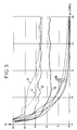
- FIG. 3 schematically shows an abacus of the distance Z R between devices for regenerating solitons on a long-distance link, and the separation ⁇ k1 between two channels having wavelengths ⁇ k and ⁇ 1 , where ⁇ 1 is the smallest wavelength of the WDM band in a multi-wavelength system of transmissions by solitons (case where D ' 0 ⁇ 0).
- the curves on this abacus are identified on the right side of the figure by a parameter p , which represents the number of bit time periods which separate the two signals at a distance Z R in km for a difference in wavelength ⁇ k1 in nm.
- broken lines can guide the reader's eye.
- the method of the invention is perfectly compatible with dispersion management, as described in the documents cited above, or any other system to dispersion management. Just replace the fixed parameters of the equations exposed above by actual values, which are calculated according to the methods sketched below.
- the system comprises a plurality of q fiber sections (t 1 , t 2 , ... t k , ... t q ), each having a length L k and a dispersion slope D ' 0 ( ⁇ 0 k ) which is zero for the wavelength ⁇ 0k , respectively.
- the effective dispersion D eff ( ⁇ ) can be calculated, as well as the effective wavelength ⁇ 0. eff of zero dispersion, and the slope of the dispersion D ' 0 .eff .
- FIG. 5 shows the results of the simulations of the quality factor as a function of the distance, for a WDM system designed according to the rules set out above.
- the parameters chosen to perform the calculations were as follows: four channels of 10 Gbit / s each for a WDM 4x10 7 b / s link, with synchronous amplitude modulation of the solitons, and filtering using a barbed filter.
- Other parameters are set as follows:
- ⁇ 0 1.5528 nm
- the solitons are coded for the simulation with a pseudo-random sequence of 2 7 -1 bits without initial correlation. The propagation over a distance of 20,000 km is calculated using the non-linear Schroedinger equation via the increment method in Fourier analysis.
- the NR curves show the quality factor of four channels without regeneration; curves A, B, C, D show the quality factor of the four channels with synchronous regeneration according to the method of the invention.
- the quality factor remains perfectly acceptable even beyond of 20,000 km.
- the 20,000 km eye diagrams shown for four channels show that the intensity noise is responsible for the performance degradation on the channel A, relative to channel D. Indeed, the time jitter Gordon-Haus presents on arrival, in addition to the effects of collision between solitons and WDM interactions, are converted into amplitude noise at the regenerator output.
- the device of the invention has been described by making reference to only a few examples of achievements using such or such parameters of a WDM system, with some devices of the known art to constitute a regenerated WDM system.
Landscapes
- Engineering & Computer Science (AREA)
- Computer Networks & Wireless Communication (AREA)
- Signal Processing (AREA)
- Physics & Mathematics (AREA)
- Electromagnetism (AREA)
- Optical Communication System (AREA)
- Stabilization Of Oscillater, Synchronisation, Frequency Synthesizers (AREA)
Claims (13)
- Verfahren zum Inline-Regenerieren von optischen Signalen, die sich auf einer optischen Faser zwischen einem Sender und einem Empfänger ausbreiten, wobei die Signale die Form einer Folge von Bits haben, die durch Solitonen dargestellt sind, die insbesondere durch eine Ausbreitungswellenlänge und einen Bittakt gekennzeichnet sind, welches die folgenden Schritte umfaßt:dadurch gekennzeichnet, daßdie Verstärkung des zu regenerierenden optischen Signals, um eventuelle Verluste auszugleichen;die Abnahme eines Teils des zu regenerierenden optischen Signals über einen an die Faser gekoppelten optischen Koppler;die Wiederherstellung eines Taktsignals ausgehend von der Bitfolge im abgenommenen Teil;die Anlegung des Taktsignals über eine geeignete Phasenverschiebung an einen optischen Modulator, um die synchrone Modulation des zu regenerierenden optischen Signals zu erhalten;die spektrale Filterung der Solitonen des zu regenerierenden optischen Signals nach der synchronen Modulation;die Solitonen durch eine Vielzahl m von Ausbreitungswellenlängen gekennzeichnet sind, die in einem Spektralband mit den Endpunkten λ1 und λn, der kleinsten bzw. der größten der Wellenlängen der Vielzahl, liegen;die Wiederherstellung eines Taktsignals ausgehend von einer Wellenlänge λk erfolgt, die zwischen den Wellenlängen λ1 und λn liegt, so daß τg(λk)ZR = kT und daßdie Regenerierung bei einer Entfernung ZR zwischen dem Sender und dem optischen Modulator oder zwischen zwei aufeinanderfolgenden Modulatoren ausgeführt wird, wobei die Entfernung ZR so ausgewählt wird, daß ihr Produkt mit der Differenz der Ankunftszeit δτg = τg(λn) - τg(λ1) für ZR in km, δτg in ps.km-1 die Bedingung erfüllt:worin k eine ganze Zahl ist und T die Bitzeit ist.

- Verfahren nach Anspruch 1, dadurch gekennzeichnet, daß die Entfernung ZR derart gewählt wird, daß ihr Produkt mit der Gruppenzeitendifferenz δτg = τg(λn) - τg(λ1) die Bedingung erfüllt:worin N > 4.

- Verfahren zum Inline-Regenerieren von optischen Signalen, die sich auf einer optischen Faser zwischen einem Sender und einem Empfänger ausbreiten, wobei die Signale die Form einer Folge von Bits haben, die durch Solitonen dargestellt sind, die insbesondere durch eine Ausbreitungswellenlänge und einen Bittakt gekennzeichnet sind, welches die folgenden Schritte umfaßt:dadurch gekennzeichnet, daßdie Verstärkung des zu regenerierenden optischen Signals, um eventuelle Verluste auszugleichen;die Abnahme eines Teils des zu regenerierenden optischen Signals über einen an die Faser gekoppelten optischen Koppler;die Wiederherstellung eines Taktsignals ausgehend von der Bitfolge im abgenommenen Teil;die Anlegung des Taktsignals über eine geeignete Phasenverschiebung an einen optischen Modulator, um die synchrone Modulation des zu regenerierenden optischen Signals zu erhalten;die spektrale Filterung der Solitonen des zu regenerierenden optischen Signals nach der synchronen Modulation;die Solitonen durch eine Vielzahl m von Ausbreitungswellenlängen gekennzeichnet sind, die aus n Wellenlängen λ1,...λn ausgewählt sind, die in einem Spektralband mit den Endpunkten λ1 und λn, der kleinsten bzw. der größten der Wellenlängen der Vielzahl, liegen;die Wiederherstellung eines Taktsignals ausgehend von einer Wellenlänge λk erfolgt, die zwischen den Wellenlängen λ1 und λn liegt; so daß τg(λk)ZR = kT und daßdie Regenerierung bei einer Entfernung ZR zwischen dem Sender und dem optischen Modulator oder zwischen zwei aufeinanderfolgenden Modulatoren mit λj - λj-1 = Δλ, ∀ j > 0, j eine ganze Zahl ist, und
- Verfahren nach einem der vorhergehenden Ansprüche, dadurch gekennzeichnet, daß die optische Faser eine Vielzahl von Faserabschnitten umfaßt, wobei jeder Abschnitt teilweise durch eine Länge und durch einen Wert der chromatischen Streuung gekennzeichnet ist, wobei das Verfahren außerdem die Steuerung der Streuung der Faserabschnitte umfaßt.
- Optisches Übertragungssystem für Signale, die die Form einer Folge von Bits haben, die durch Solitonen dargestellt sind, die insbesondere durch eine Ausbreitungswellenlänge und einen Bittakt gekennzeichnet sind, wobei das System wenigstens einen Sender und einen Empfänger sowie eine optische Faser umfaßt, die die beiden verbindet; wobei das System außerdem wenigstens eine optische Regenerierungseinrichtung umfaßt, die eine Schaltung zur Wiederherstellung des Taktes und einen optischen Modulator sowie ein Spektralfilter umfaßt;
dadurch gekennzeichnet, daßder Sender Solitonen auf einer Vielzahl von Wellenlängen sendet, die in einem Spektralband mit den Endpunkten λ1 und λn, der kleinsten bzw. der größten der Wellenlängen der Vielzahl, liegen;wobei die verschiedenen Wellenlängen jeweils zu verschiedenen Gruppenzeiten τg(λ1), τg(λn) gehören, wobei diese Gruppenzeiten durch eine Gruppenzeitendifferenz δτg = τg(λn) - τg(λ1) gekennzeichnet sind;und daß die optische Regenerierungseinrichtung bei einer Entfernung ZR zwischen dem Sender und dem optischen Modulator oder zwischen zwei aufeinanderfolgenden Modulatoren angeordnet ist, wobei die Entfernung ZR derart gewählt ist, daß ihr Produkt mit der Gruppenzeitendifferenz δτg = τg(λn) - τg(λ1) für ZR in km, δτg in ps.km-1 die Bedingung erfüllt:worin k eine ganze Zahl und T die Bitzeit ist.
- System nach Anspruch 5, dadurch gekennzeichnet, daß die Entfernung ZR so gewählt ist, daß ihr Produkt mit der Differenz der Gruppenzeiten δτg = τg(λn) - τg(λ1) die Bedingung erfüllt:worin N > 4.

- Optisches Übertragungssystem für Signale, die die Form einer Folge von Bits haben, die durch Solitonen dargestellt sind, die insbesondere durch eine Ausbreitungswellenlänge und einen Bittakt gekennzeichnet sind, wobei das System wenigstens einen Sender und einen Empfänger sowie eine optische Faser umfaßt, die die beiden verbindet; wobei das System außerdem wenigstens eine optische Regenerierungseinrichtung umfaßt, die eine Schaltung zur Wiederherstellung des Taktes und einen optischen Modulator sowie ein Spektralfilter umfaßt;
dadurch gekennzeichnet, daßder Sender Solitonen auf einer Vielzahl von Wellenlängen sendet, die in einem Spektralband mit den Endpunkten λ1 und λn, der kleinsten bzw. der größten der Wellenlängen der Vielzahl, liegen;wobei die verschiedenen Wellenlängen jeweils zu verschiedenen Gruppenzeiten τg(λ1), τg(λn) gehören, wobei diese Gruppenzeiten durch eine Gruppenzeitendifferenz δτg = τg(λn) - τg(λ1) gekennzeichnet sind;und daß die optische Regenerierungseinrichtung bei einer Entfernung ZR zwischen dem Sender und dem optischen Modulator oder zwischen zwei aufeinanderfolgenden Modulatoren angeordnet ist,und daß das WDM-System eine Vielzahl m von WDM-Kanälen verwendet, die aus n Kanälen (c1,...cn) mit den jeweiligen Wellenlängen λ1, λ2,...,λn ausgewählt sind, wobei λj - λj-1 = Δλ, ∀ j > 0, j eine ganze Zahl ist, und - System nach Anspruch 7, dadurch gekennzeichnet, daß N = M = 1, nämlich x = 2, y = 1/2, und
- System nach einem der Ansprüche 5 bis 8, dadurch gekennzeichnet, daß es eine Vielzahl von q Faserabschnitten umfaßt, wobei jeder Abschnitt teilweise durch eine Länge und durch einen Wert der chromatischen Streuung gekennzeichnet ist und das Verfahren nach einem der Ansprüche 1 bis 4 außerdem die Steuerung der Streuung der Faserabschnitte umfaßt.
- System nach Anspruch 9, dadurch gekennzeichnet, daß q nach unendlich strebt, die Wellenlänge jedes Abschnittes nach dem unendlich Kleinen strebt, die chromatische Streuung kontinuierlich variiert und die effektive Streuung durch das Integral berechnet wird.
- System nach einem der vorhergehenden Ansprüche, dadurch gekennzeichnet, daß die effektive Steigung der Streuung Null ist: D0,eff = 0, wobei Δλ = Tbit/ZRD.
- System nach Anspruch 11, dadurch gekennzeichnet, daß die Steigung der Streuung effektiv Null ist:
- Regenerierungseinrichtung für Solitonen, die eine Schaltung RH zur Wiederherstellung des Taktes, der mit dem Bittakt eines Solitonsignals auf dem Übertragungskanal über einen optischen Koppler synchronisiert ist, Mittel zur Einstellung der Phase Φ, beispielsweise eine Leitung mit optischer Verzögerung, und einen Modulator für die Intensität und/oder die Phase umfaßt, der vom Taktsignal RF gesteuert wird,
dadurch gekennzeichnet, daß sie außerdem ein geripptes, führendes optisches Filter umfaßt, das dazu dient, die Solitonpulse mit einer Vielzahl von Wellenlängen in die gleiche zeitliche Position zu verlegen.
Applications Claiming Priority (2)
| Application Number | Priority Date | Filing Date | Title |
|---|---|---|---|
| FR9600732 | 1996-01-23 | ||
| FR9600732A FR2743964B1 (fr) | 1996-01-23 | 1996-01-23 | Methode et dispositif de regeneration en ligne d'un signal transmis par solitons multiplexes en longueur d'onde via la modulation synchrone et systeme de telecommunications optiques utilisant la methode |
Publications (2)
| Publication Number | Publication Date |
|---|---|
| EP0786877A1 EP0786877A1 (de) | 1997-07-30 |
| EP0786877B1 true EP0786877B1 (de) | 1999-12-01 |
Family
ID=9488368
Family Applications (1)
| Application Number | Title | Priority Date | Filing Date |
|---|---|---|---|
| EP97400106A Expired - Lifetime EP0786877B1 (de) | 1996-01-23 | 1997-01-20 | Verfahren und Anordnung zum Inline-Regenerieren eines übertragenen Wellenlängenmultiplexsignals durch synchrone Modulation und optisches Übertragungssystem welches dieses Verfahren benutzt |
Country Status (8)
| Country | Link |
|---|---|
| US (1) | US5801862A (de) |
| EP (1) | EP0786877B1 (de) |
| JP (1) | JPH09214469A (de) |
| CN (1) | CN1166736A (de) |
| AT (1) | ATE187290T1 (de) |
| CA (1) | CA2195796A1 (de) |
| DE (1) | DE69700844T2 (de) |
| FR (1) | FR2743964B1 (de) |
Families Citing this family (21)
| Publication number | Priority date | Publication date | Assignee | Title |
|---|---|---|---|---|
| US5986789A (en) * | 1996-03-07 | 1999-11-16 | Nippon Telegraph And Telephone Corporation | Optical transmission line and optical transmission system |
| FR2746237B1 (fr) * | 1996-03-18 | 1998-04-17 | Procede et systeme de transmission optique a solitons | |
| FR2759516B1 (fr) * | 1997-02-10 | 1999-03-26 | Alsthom Cge Alcatel | Procede et dispositif de regeneration en ligne d'un signal transmis par solitons multiplexes en longueur d'onde et systeme de telecommunications optiques comprenant un tel dispositif de regeneration |
| FR2759832B1 (fr) * | 1997-02-18 | 1999-03-26 | Alsthom Cge Alcatel | Regeneration optique pour des systemes de transmission a fibre optique a signaux solitons et a multiplexage de longueur d'onde |
| FR2764451B1 (fr) * | 1997-06-05 | 1999-07-30 | Alsthom Cge Alcatel | Systeme de transmission a fibre optique a signaux solitons, a multiplexage de longueur d'onde et a absorbants saturables |
| FR2770063B1 (fr) * | 1997-10-16 | 1999-12-03 | Alsthom Cge Alcatel | Systemes de transmission a fibre optique a signaux solitons et a multiplexage de longueur d'onde |
| FR2770001B1 (fr) | 1997-10-16 | 1999-12-03 | Alsthom Cge Alcatel | Reparation de systemes sous-marins de transmission a fibre optique a signaux solitons et a multiplexage de longueur d'onde |
| FR2779297B1 (fr) * | 1998-05-28 | 2000-09-08 | Alsthom Cge Alcatel | Systeme de transmission a fibre optique a signaux solitons et a double filtrage |
| US6407842B1 (en) * | 1998-10-28 | 2002-06-18 | Tycom (Us) Inc. | Method and apparatus for transmitting a WDM optical signal having nonuniform channel spacings |
| FR2785749B1 (fr) * | 1998-11-09 | 2000-12-15 | Cit Alcatel | Equilibrage des collisions dans un systeme de transmission a fibre optique a signaux solitons |
| US6476953B1 (en) | 1999-08-18 | 2002-11-05 | Fujitsu Network Communications, Inc. | Wavelength preserving regenerator for DWDM transmission systems |
| US6721512B1 (en) * | 2000-03-02 | 2004-04-13 | Nortel Networks Limited | High speed jitter correction and adaptive chromatic dispersion compensation in optical dispersion compensation in optical systems using RZ format |
| US6496615B2 (en) * | 2000-05-22 | 2002-12-17 | Sumitomo Electric Industries, Ltd. | WDM transmission system |
| GB2371160B (en) * | 2001-01-10 | 2004-06-30 | Univ Aston | Optical pulse regenerating transmission lines |
| US7200344B1 (en) | 2001-05-10 | 2007-04-03 | Fujitsu Limited | Receiver and method for a multichannel optical communication system |
| US6941078B1 (en) * | 2001-05-10 | 2005-09-06 | Fujitsu Limited | Method and system for communicating a clock signal over an optical link |
| US7483639B2 (en) | 2001-05-10 | 2009-01-27 | Fujitsu Limited | Method and system for transmitting information in an optical communication system using distributed amplification |
| US7068943B2 (en) * | 2003-02-13 | 2006-06-27 | Corning Incorporated | Devices and methods for dynamic dispersion compensation |
| CN100387651C (zh) * | 2005-03-02 | 2008-05-14 | 云南云天化股份有限公司 | 超细复合粉体增韧聚甲醛材料及其制备方法 |
| US7623798B1 (en) * | 2005-10-04 | 2009-11-24 | Sprint Communications Company L.P. | Polarization mode dispersion mitigation of multiple optical communication channels |
| US8400452B2 (en) * | 2008-05-08 | 2013-03-19 | Motorola Solutions, Inc. | Method and system for segmented propagation visualization |
Family Cites Families (3)
| Publication number | Priority date | Publication date | Assignee | Title |
|---|---|---|---|---|
| US5369520A (en) * | 1992-05-22 | 1994-11-29 | At&T Corp. | Optical regeneration circuit |
| US5357364A (en) | 1992-06-25 | 1994-10-18 | At&T Bell Laboratories | Soliton transmission system having sliding-frequency guiding filters |
| JP2966294B2 (ja) * | 1994-09-12 | 1999-10-25 | ケイディディ株式会社 | 光伝送システム |
-
1996
- 1996-01-23 FR FR9600732A patent/FR2743964B1/fr not_active Expired - Fee Related
-
1997
- 1997-01-20 AT AT97400106T patent/ATE187290T1/de active
- 1997-01-20 EP EP97400106A patent/EP0786877B1/de not_active Expired - Lifetime
- 1997-01-20 DE DE69700844T patent/DE69700844T2/de not_active Expired - Fee Related
- 1997-01-22 CA CA002195796A patent/CA2195796A1/fr not_active Abandoned
- 1997-01-22 CN CN97101037.4A patent/CN1166736A/zh active Pending
- 1997-01-22 US US08/787,215 patent/US5801862A/en not_active Expired - Fee Related
- 1997-01-23 JP JP9010560A patent/JPH09214469A/ja not_active Withdrawn
Also Published As
| Publication number | Publication date |
|---|---|
| EP0786877A1 (de) | 1997-07-30 |
| US5801862A (en) | 1998-09-01 |
| DE69700844T2 (de) | 2000-06-29 |
| CN1166736A (zh) | 1997-12-03 |
| CA2195796A1 (fr) | 1997-07-24 |
| FR2743964A1 (fr) | 1997-07-25 |
| FR2743964B1 (fr) | 1998-03-13 |
| ATE187290T1 (de) | 1999-12-15 |
| DE69700844D1 (de) | 2000-01-05 |
| JPH09214469A (ja) | 1997-08-15 |
Similar Documents
| Publication | Publication Date | Title |
|---|---|---|
| EP0786877A1 (de) | Verfahren und Anordnung zum Inline-Regenerieren eines übertragenen Wellenlängenmultiplexsignals durch synchrone Modulation und optisches Übertragungssystem welches dieses Verfahren benutzt | |
| EP0897624B1 (de) | Verfahren und vorrichtung zur online wiedererzeugung eines durch wellenlängenmultiplexsolitons übertragenen signals und optisches nachrichtenübertragungssystem mit einer derartigen vorrichtung zur wiedererzeugung | |
| US5946119A (en) | Wavelength division multiplexed system employing optimal channel modulation | |
| EP0862286B1 (de) | Optische Regenerierung für faseroptische Übertragungssysteme mit nicht-Soliton Signalen | |
| US20030147646A1 (en) | Combined phase and intensity modulation in optical communication systems | |
| FR2724510A1 (fr) | Systeme de transmission optique | |
| EP0763912B1 (de) | Rein optischer Frequenzverdoppler und dieser verwendender Solitonregenerator | |
| EP0576358B1 (de) | Verfahren und Vorrichtung zur optischen Übertragung von Solitonen über lange Abstände | |
| JPH11239099A (ja) | 同期偏波スクランブラを用いた光通信システム及び光受信装置 | |
| EP1969748B1 (de) | Optische übertragung zwischen einem zentralen endgerät und mehreren client-endgeräten über ein optisches netzwerk | |
| CA2319961A1 (fr) | Regenerateur de signaux optiques multiplexes en longueur d'onde | |
| EP0883256B1 (de) | Soliton faseroptisches Wellenlängenmultiplexiertes Übertragungssystem mit sättigbarem Absorber | |
| EP0961425A1 (de) | Soliton Übertragungssystem mit Doppel Filterung | |
| EP0910185B1 (de) | Soliton und WDM faseroptisches Übertragungssystem | |
| JPH07336298A (ja) | 波長多重光ソリトン伝送法 | |
| Kaur et al. | Performance analysis of OTDM link at 40 Gbps | |
| EP0924883A1 (de) | Reduktion von kollisionsinduziertem Zeitjitter in einem Wellenlängenmultiplexsolitonübertragungssystem durch Veränderung der Wellenlängen | |
| EP0910186B1 (de) | Reparierung von Soliton und WDM faseroptischen Unterwasserübertragungssystemen | |
| WO2002019574A1 (fr) | Regenerateur tout-optique pour signaux multiplexes en longueur d'onde | |
| WO2002001766A1 (fr) | Compensation de dispersion chromatique dans un systeme de transmission optique large bande | |
| Marco et al. | Device and method for compensating polarization mode dispersion in an optical communication system | |
| EP1021004A1 (de) | Verfahren und Vorrichtung zur Stabilisierung von optischen Solitonen | |
| Blumenthal | Error Rate Measurement Instrumentation For Multiwavelength Optical Switching | |
| Tsuritani et al. | 340 Gbit/s (32/spl times/10.66 Gbit/s) WDM transmission over 6,054 km using hybrid fiber spans of large core fiber and WDM fiber with low dispersion slope | |
| EP0859482A1 (de) | Optischer Regenerator für Soliton faseroptische WDM Systeme |
Legal Events
| Date | Code | Title | Description |
|---|---|---|---|
| PUAI | Public reference made under article 153(3) epc to a published international application that has entered the european phase |
Free format text: ORIGINAL CODE: 0009012 |
|
| AK | Designated contracting states |
Kind code of ref document: A1 Designated state(s): AT BE CH DE DK ES FR GB IT LI NL SE |
|
| 17P | Request for examination filed |
Effective date: 19980130 |
|
| 17Q | First examination report despatched |
Effective date: 19980423 |
|
| GRAG | Despatch of communication of intention to grant |
Free format text: ORIGINAL CODE: EPIDOS AGRA |
|
| GRAG | Despatch of communication of intention to grant |
Free format text: ORIGINAL CODE: EPIDOS AGRA |
|
| GRAH | Despatch of communication of intention to grant a patent |
Free format text: ORIGINAL CODE: EPIDOS IGRA |
|
| GRAH | Despatch of communication of intention to grant a patent |
Free format text: ORIGINAL CODE: EPIDOS IGRA |
|
| GRAA | (expected) grant |
Free format text: ORIGINAL CODE: 0009210 |
|
| RAP1 | Party data changed (applicant data changed or rights of an application transferred) |
Owner name: ALCATEL |
|
| AK | Designated contracting states |
Kind code of ref document: B1 Designated state(s): AT BE CH DE DK ES FR GB IT LI NL SE |
|
| PG25 | Lapsed in a contracting state [announced via postgrant information from national office to epo] |
Ref country code: SE Free format text: THE PATENT HAS BEEN ANNULLED BY A DECISION OF A NATIONAL AUTHORITY Effective date: 19991201 Ref country code: NL Free format text: LAPSE BECAUSE OF FAILURE TO SUBMIT A TRANSLATION OF THE DESCRIPTION OR TO PAY THE FEE WITHIN THE PRESCRIBED TIME-LIMIT Effective date: 19991201 Ref country code: ES Free format text: THE PATENT HAS BEEN ANNULLED BY A DECISION OF A NATIONAL AUTHORITY Effective date: 19991201 Ref country code: AT Free format text: LAPSE BECAUSE OF FAILURE TO SUBMIT A TRANSLATION OF THE DESCRIPTION OR TO PAY THE FEE WITHIN THE PRESCRIBED TIME-LIMIT Effective date: 19991201 |
|
| REF | Corresponds to: |
Ref document number: 187290 Country of ref document: AT Date of ref document: 19991215 Kind code of ref document: T |
|
| REG | Reference to a national code |
Ref country code: CH Ref legal event code: EP |
|
| REF | Corresponds to: |
Ref document number: 69700844 Country of ref document: DE Date of ref document: 20000105 |
|
| GBT | Gb: translation of ep patent filed (gb section 77(6)(a)/1977) |
Effective date: 19991221 |
|
| PG25 | Lapsed in a contracting state [announced via postgrant information from national office to epo] |
Ref country code: BE Free format text: LAPSE BECAUSE OF NON-PAYMENT OF DUE FEES Effective date: 20000131 |
|
| ITF | It: translation for a ep patent filed | ||
| PG25 | Lapsed in a contracting state [announced via postgrant information from national office to epo] |
Ref country code: DK Free format text: LAPSE BECAUSE OF FAILURE TO SUBMIT A TRANSLATION OF THE DESCRIPTION OR TO PAY THE FEE WITHIN THE PRESCRIBED TIME-LIMIT Effective date: 20000301 |
|
| NLV1 | Nl: lapsed or annulled due to failure to fulfill the requirements of art. 29p and 29m of the patents act | ||
| BERE | Be: lapsed |
Owner name: ALCATEL Effective date: 20000131 |
|
| PLBE | No opposition filed within time limit |
Free format text: ORIGINAL CODE: 0009261 |
|
| STAA | Information on the status of an ep patent application or granted ep patent |
Free format text: STATUS: NO OPPOSITION FILED WITHIN TIME LIMIT |
|
| 26N | No opposition filed | ||
| PG25 | Lapsed in a contracting state [announced via postgrant information from national office to epo] |
Ref country code: LI Free format text: LAPSE BECAUSE OF NON-PAYMENT OF DUE FEES Effective date: 20010131 Ref country code: CH Free format text: LAPSE BECAUSE OF NON-PAYMENT OF DUE FEES Effective date: 20010131 |
|
| REG | Reference to a national code |
Ref country code: CH Ref legal event code: PL |
|
| REG | Reference to a national code |
Ref country code: GB Ref legal event code: IF02 |
|
| PGFP | Annual fee paid to national office [announced via postgrant information from national office to epo] |
Ref country code: GB Payment date: 20040112 Year of fee payment: 8 |
|
| PGFP | Annual fee paid to national office [announced via postgrant information from national office to epo] |
Ref country code: DE Payment date: 20040123 Year of fee payment: 8 |
|
| PGFP | Annual fee paid to national office [announced via postgrant information from national office to epo] |
Ref country code: FR Payment date: 20040128 Year of fee payment: 8 |
|
| PG25 | Lapsed in a contracting state [announced via postgrant information from national office to epo] |
Ref country code: IT Free format text: LAPSE BECAUSE OF NON-PAYMENT OF DUE FEES Effective date: 20050120 Ref country code: GB Free format text: LAPSE BECAUSE OF NON-PAYMENT OF DUE FEES Effective date: 20050120 |
|
| PG25 | Lapsed in a contracting state [announced via postgrant information from national office to epo] |
Ref country code: DE Free format text: LAPSE BECAUSE OF NON-PAYMENT OF DUE FEES Effective date: 20050802 |
|
| GBPC | Gb: european patent ceased through non-payment of renewal fee |
Effective date: 20050120 |
|
| PG25 | Lapsed in a contracting state [announced via postgrant information from national office to epo] |
Ref country code: FR Free format text: LAPSE BECAUSE OF NON-PAYMENT OF DUE FEES Effective date: 20050930 |
|
| REG | Reference to a national code |
Ref country code: FR Ref legal event code: ST |