EP0924883A1 - Reduktion von kollisionsinduziertem Zeitjitter in einem Wellenlängenmultiplexsolitonübertragungssystem durch Veränderung der Wellenlängen - Google Patents
Reduktion von kollisionsinduziertem Zeitjitter in einem Wellenlängenmultiplexsolitonübertragungssystem durch Veränderung der Wellenlängen Download PDFInfo
- Publication number
- EP0924883A1 EP0924883A1 EP98402950A EP98402950A EP0924883A1 EP 0924883 A1 EP0924883 A1 EP 0924883A1 EP 98402950 A EP98402950 A EP 98402950A EP 98402950 A EP98402950 A EP 98402950A EP 0924883 A1 EP0924883 A1 EP 0924883A1
- Authority
- EP
- European Patent Office
- Prior art keywords
- wavelengths
- wavelength
- channels
- signals
- exchange
- Prior art date
- Legal status (The legal status is an assumption and is not a legal conclusion. Google has not performed a legal analysis and makes no representation as to the accuracy of the status listed.)
- Withdrawn
Links
- 230000005540 biological transmission Effects 0.000 title claims abstract description 52
- 230000009467 reduction Effects 0.000 title claims description 3
- 239000000835 fiber Substances 0.000 claims abstract description 14
- 238000000034 method Methods 0.000 claims description 27
- 238000006243 chemical reaction Methods 0.000 claims description 23
- 230000008859 change Effects 0.000 claims description 9
- 238000001914 filtration Methods 0.000 claims description 4
- 230000008569 process Effects 0.000 claims description 2
- 230000001268 conjugating effect Effects 0.000 claims 1
- 230000000694 effects Effects 0.000 abstract description 11
- 230000001360 synchronised effect Effects 0.000 description 10
- 239000006185 dispersion Substances 0.000 description 8
- 230000007423 decrease Effects 0.000 description 7
- 230000003287 optical effect Effects 0.000 description 5
- 230000008929 regeneration Effects 0.000 description 3
- 238000011069 regeneration method Methods 0.000 description 3
- 239000004065 semiconductor Substances 0.000 description 3
- 238000001228 spectrum Methods 0.000 description 3
- 239000002250 absorbent Substances 0.000 description 2
- 230000002745 absorbent Effects 0.000 description 2
- 239000013307 optical fiber Substances 0.000 description 2
- 230000008054 signal transmission Effects 0.000 description 2
- 230000005374 Kerr effect Effects 0.000 description 1
- 230000002159 abnormal effect Effects 0.000 description 1
- 230000002457 bidirectional effect Effects 0.000 description 1
- 230000001186 cumulative effect Effects 0.000 description 1
- 230000003993 interaction Effects 0.000 description 1
- 230000004048 modification Effects 0.000 description 1
- 238000012986 modification Methods 0.000 description 1
- 230000003595 spectral effect Effects 0.000 description 1
- 230000002123 temporal effect Effects 0.000 description 1
Images
Classifications
-
- H—ELECTRICITY
- H04—ELECTRIC COMMUNICATION TECHNIQUE
- H04B—TRANSMISSION
- H04B10/00—Transmission systems employing electromagnetic waves other than radio-waves, e.g. infrared, visible or ultraviolet light, or employing corpuscular radiation, e.g. quantum communication
- H04B10/25—Arrangements specific to fibre transmission
- H04B10/2507—Arrangements specific to fibre transmission for the reduction or elimination of distortion or dispersion
- H04B10/25077—Arrangements specific to fibre transmission for the reduction or elimination of distortion or dispersion using soliton propagation
Definitions
- the present invention relates to a fiber optic transmission system with wavelength multiplexed soliton signals and a method of transmission in such a system, which reduce the effects of jitter collision. It also relates to a device and a method for exchanging lengths wave in a fiber optic transmission system with soliton signals and wavelength multiplexing.
- soliton or soliton pulses in the part of an optical fiber with abnormal dispersion is a known phenomenon.
- Solitons are pulse signals of sech 2 form. With this pulse shape, the non-linearity in the corresponding part of the fiber compensates for the dispersion of the optical signal.
- the transmission of solitons is modeled in a known manner by the non-linear Schrödinger equation.
- soliton signal optics Furthermore, to increase the throughput of free transmission systems soliton signal optics, it has also been proposed to use a multiplexing of wavelength (in English "wavelength division multiplexing or WDM). In this case, it is considered advantageous to use sliding guiding filters of the type Fabry Perot, which are fully compatible with multiplex signals in wave length. On the other hand. the use of synchronous modulators or of saturable absorbents for the regeneration of soliton signals multiplexed into wavelength is problematic, due to the difference in group speed between signals from different channels.
- the subject of the invention is a solution to the problem of managing collisions between solitons in a wavelength multiplex transmission system; it avoids having to vary the dispersion profile of the transmission fiber the along the transmission system.
- the invention is particularly applicable advantageously to transmission systems with wavelength multiplexing in which the wavelengths are chosen so as to ensure synchronicity bit times of the different channels at given intervals.
- the invention provides a simple solution, which limits the temporal jitter due to collisions between solitons.
- the invention provides a fiber transmission system optical wavelength multiplexing and soliton signals, comprising at least at least once means for exchanging wavelengths of at least two channels, so as to change the sign of the residual frequency variation induced by the asymmetric collisions on the signals of said channels.
- the wavelengths ( ⁇ 1 to ⁇ n ) of the different channels of the multiplex constitute a set comprising a lower half and an upper half
- the exchange means exchange the wavelengths of at least at least two channels, so that signals transmitted on a wavelength of one of said halves are transmitted on a wavelength of the other of said halves.
- the exchange means carry out the exchange of the wavelengths so that the signals transmitted on a wavelength ⁇ i of one of said halves are transmitted on a length of wave ⁇ n-i + 1 of the other of said halves, i being an integer taking at least one value between 1 and n.
- the exchange means further carry out the exchange of wavelengths so that the signals transmitted on a wavelength ⁇ n-i + 1 of one of said halves are transmitted over a length of wave ⁇ i of the other of said halves.
- the integer i can preferably take all the possible values between 1 and n.
- the transmission system comprises means single exchange arranged substantially in the middle of the transmission system.
- the system includes a plurality of exchange means spaced along the transmission system.
- the invention also relates to a method for transmitting soliton signals in wavelength multiplexing, comprising at least one step for exchanging wavelengths of at least two channels, so as to change the sign of the variation of residual frequency induced by asymmetric collisions on the signals of the said canals.
- the wavelengths ( ⁇ 1 to ⁇ n ) of the different channels of the multiplex constitute a set comprising a lower half and an upper half, and in that the channel exchange step is carried out so that signals transmitted on a wavelength of one of said halves are transmitted on a wavelength of the other of said halves.
- the wavelengths are exchanged advantageously so that the signals transmitted on a wavelength ⁇ i of one of said halves are transmitted on a wavelength ⁇ n-1 + 1 of the other of the said halves, i being an integer taking at least one value between 1 and n.
- the exchange step may further comprise the exchange of wavelengths so that the signals transmitted over a wavelength ⁇ n-i + 1 of one of said halves are transmitted over a length of wave ⁇ i of the other of said halves.
- the integer i takes all the possible values between 1 and n.
- the process can include a single exchange step, taking place substantially after half the propagation time.
- the method can also include a plurality of exchange steps.
- the invention also relates to the application of such a method to reducing the collision jitter.
- the converters carry out the exchange of wavelengths so that the signals received on a wavelength ⁇ i of one of said halves are transmitted on a wavelength ⁇ n-i +1 of the other of said halves, and vice-versa, i being an integer taking at least one value between 1 and n.
- the device comprises 2E (n / 2) converters, n being the number of channels.
- the exchange step advantageously comprises the exchange of a wavelength ⁇ i of one of said halves and of a wavelength ⁇ n-i + 1 of the other of said halves, i being an integer taking at least one value between 1 and n.
- the integer i takes all the values between 1 and E (n / 2), n being the number of channels.
- said first and second conversion means comprise four-wave mixers for combining the signals with respect to a frequency ( ⁇ 1 + ⁇ n ) / 2 median of the extreme frequencies of the multiplex.
- the said first means of conversion, or respectively the second conversion means preferably further comprise filters for filter wavelengths other than those of the other half, or respectively other than those of said half.
- the conversion step comprises a conversion by mixing four waves to conjugate the signals with respect to a frequency ( ⁇ 1 + ⁇ n ) / 2 median of the extreme frequencies of the multiplex.
- the conversion step advantageously comprises a step of filtering after the four-wave mixing step.
- the invention applies to a fiber optic signal transmission system soliton and wavelength multiplexing. It is described below in reference to a system in which the different wavelengths of the multiplex are chosen so as to ensure, over a given interval, a relative shift between the different channels substantially equal to a multiple of the bit time. However, it is not not limited to a transmission system implementing such a scheme frequency allocation, and more generally applies to any system of soliton signal transmission with wavelength multiplexing.
- wavelength allocation solutions described in the articles by E. Desurvire and O. Leclerc mentioned above can be used. These articles are incorporated by reference into the present description, as regards the wavelength allocation schemes.
- Such a wavelength allocation scheme ensures, at regular intervals Z R along the fiber, a relative slip between the different channels substantially equal to a multiple of the bit time.
- the variation in wavelength ⁇ caused by a collision is given by example in the reference WDM with solitons in ultra-long distance transmission using lumped amplifiers, by Mollenauer et al., Journ. of Light. Tech. flight. 9 n ° 3, March 91; it depends on the dissymmetry of the collision, i. e. from the position of the amplifier with respect to it.
- the invention is based on the fact that this variation in wavelength accelerates the quickest solitons. i. e. those with the shortest wavelength, and slows down the slowest solitons, i. e. those with the longest wavelength. It proposes, to compensate for the effects of collisions, to exchange at least once the wavelengths of the channels of the multiplex, so as to change the sign of the residual frequency variation induced by asymmetric collisions on a channel.
- the invention proposes various embodiments of this exchange; in particular, this exchange can be carried out for all channels, or only for certain of them, as described below.
- the effect of channel exchange is a decrease - on average - in the residual frequency variation at the end of the link, which is the sum of the variations suffered on the whole link. This causes an average decrease in the jitter of collision; the exact decrease in jitter depends of course on the data present on the link, and more precisely the presence of soliton pulses - "1" - on colliding channels.
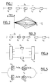
- Figure 1 shows a first embodiment of the invention; as explained above, a wavelength allocation scheme is used ensuring synchronicity or quasi-synchronicity of the bit times of the different channels at regular intervals, denoted Z R.
- a plurality of repeaters 2 1 to 2 m are provided along the transmission system, for example spaced from Z R , as described above; in the embodiment of FIG.
- the transmission system also comprises a plurality of devices 3 1 to 3 m for channel exchange ; these exchange for example all the channels of the multiplex, by transmitting over a length ⁇ n-i + 1 the signals received on the wavelength channel ⁇ i , and this for all the possible values of i between 1 and n ; if n is even, this amounts to exchanging the wavelengths of the channels so that each of the channels transmitted on a wavelength in the lower half [ ⁇ 1, ⁇ n / 2 ] is transmitted on a length d wave of the upper half [ ⁇ n / 2 + 1, ⁇ n ], and vice versa.
- n is odd, in this case we exchange the wavelengths of the lower half [ ⁇ 1, ⁇ (n-1) / 2 ] and those of the upper half [ ⁇ (n + 3) / 2, ⁇ n ]; the wavelength channel ⁇ (n + 1) / 2 can be left without modification.
- FIG. 2 shows the shape of the collision jitter ⁇ t between two repeaters, over an interval Z R of the transmission system; the ordinates give the collision jitter for the signals of the different channels of the multiplex, while the abscissas give the distance along the transmission system; the figure shows that starting from a repeater with a zero jitter of collision, the jitter of collision increases progressively and exponentially as a function of the distance, for the different channels, and this up to values of abscissa Z R / 2, ie up to the position of the wavelength exchange device. After this abscissa, ie after the signals have passed through the wavelength exchange device, the sign of the residual frequency variation induced by asymmetric collisions on the signals changes.
- the signals for which the collision jitter is positive are the signals of the channels whose wavelength is initially in the upper half [ ⁇ n / 2 + 1, ⁇ n ] of the set of lengths d 'wave; the variation in residual wavelength on the signals of these channels is positive over the first half of the path, before the means for exchanging the wavelengths.
- the signals are transported on the wavelengths of the lower half of the set of wavelengths [ ⁇ 1, ⁇ n / 2-1 ]; in this part of the link, the collision jitter is negative and decreases the cumulative value shown in Figure 2.
- the signals for which the collision jitter is positive are the signals of the channels whose length of wave is initially in the lower half [ ⁇ 1, ⁇ n / 2-1 ] of the set of wavelengths; the variation in residual wavelength on the signals of these channels is negative over the first half of the path, before the wavelength exchange means, and positive over the second half of the path.
- Figure 3 shows another embodiment of the invention; the system of transmission is similar to that of Figure 1, except that it has only one single device 4 for exchanging wavelengths, for example located in the middle of the liaison; this solution is particularly economical, and can be preferably implemented when the collision jitter accumulated over half of the link is weak enough not to be penalizing.
- FIG. 4 shows a wavelength exchange device according to the invention.
- This device comprises a demultiplexer 10 receiving the multiplex and supplying the various channels as output; the signals supplied by the demultiplexer are transmitted to wavelength converters 12 1 to 12 p ; each of these converters converts the wavelength of the signals it receives; SOA (acronym for Semiconductor Optical Amplifiers, semiconductor optical amplifiers), or four-wave mixers can be used for converters.
- SOA acronym for Semiconductor Optical Amplifiers, semiconductor optical amplifiers
- the converters advantageously change the wavelengths so that signals received on a wavelength of one of the halves is supplied at the output of the converter on the other half.
- the signals supplied at the output of the converters are then remultiplexed, in a multiplexer 14.
- the demultiplexing means demultiplex the channels on which it must not no exchange of wavelengths, for example channels 3 to 6 in the case given above.
- the means for remultiplexing the channels then receive no only the signals supplied by the converters, but also the channels having no no wavelength change.
- the converters carry out the exchange of the wavelengths so that the signals received on a wavelength ⁇ i are transmitted on a wavelength ⁇ n-i + 1 , and vice versa; in this case, i is an integer taking at least one value between 1 and n, and preferably all the possible values.
- n converters for exchange the wavelengths of all the channels. If the number n of channels is odd, the wavelength of the central channel of the multiplex is not affected, and we can provide n-1 converters to exchange the wavelengths of others canals. In general, we therefore have 2E (n / 2) converters, to exchange the maximum of canals.
- FIG. 5 shows another example of a wavelength exchange device according to the invention.
- the device of FIG. 5 operates by mixing four waves of one half of the channels of the multiplex, so as to change in one step the wavelengths of half of the channels.
- the example of an 8-channel multiplex is described with reference to FIG. 5, and the first half is called the wavelengths ⁇ 1 to ⁇ 4 , and the second half is the wavelength ⁇ 5 to ⁇ 8 .
- the device of FIG. 5 comprises, at the input, means for separating the multiplex into first and second signals, the first signal comprising the channels whose wavelength belongs to the first half, and the second signal including the channels whose wavelength belongs to the second half; these means for example comprise two filters 16 and 18 receiving the multiplex, and filtering signals from the first and second half, respectively.
- the first and second signals are then supplied to four wave mixers 20 and 22; these mixers also receive a signal at a central wavelength ⁇ s , which is used for mixing four waves.
- this wavelength is ( ⁇ 1 + ⁇ 8 ) / 2.
- the four-wave mixer 20 receiving the wavelength channels ⁇ 1 to ⁇ 4 and the signal at ⁇ s outputs wavelength signals 2 ⁇ s - ⁇ 4 , 2 ⁇ s - ⁇ 3 , 2 ⁇ s - ⁇ 2 , 2 ⁇ s - ⁇ 1 , ie symmetrical of the original wavelengths with respect to the wavelength ⁇ s ; if necessary, the other signals supplied by the four-wave mixer are filtered. Given the choice of ⁇ s , it appears that the signals initially received on the wavelengths ⁇ 1 to ⁇ 4 are transmitted on the wavelengths ⁇ 8 to ⁇ 5 .
- the four-wave mixer 22 receiving the signals on the wavelengths ⁇ 5 to ⁇ 8 outputs signals of wavelength ⁇ 4 to ⁇ 1 .
- the signals from the four-wave mixers are then combined to reform an eight-channel multiplex.
- the assembly of FIG. 5 allows an overall treatment of half of the channels, in each of the mixers; with respect to the embodiment of FIG. 5, we avoids having to provide one converter per channel.
- the assembly of Figure 5 can be adapted, and is not limited to eight channels; he is this assembly can be used for any number of channels.
- the central channel can be transmitted directly, without go through one of the four wave mixers.
- the invention is not limited to the embodiments described for example.
- the wavelength allocation scheme is in no way limited to the examples described. It should also be noted that, with respect to the modes of realization described, add or remove filters or amplifiers, depending needs. Finally. the invention has been described in the case of a transmission unidirectional. It obviously applies to a bidirectional transmission.
Landscapes
- Physics & Mathematics (AREA)
- Electromagnetism (AREA)
- Engineering & Computer Science (AREA)
- Computer Networks & Wireless Communication (AREA)
- Signal Processing (AREA)
- Optical Communication System (AREA)
- Optical Modulation, Optical Deflection, Nonlinear Optics, Optical Demodulation, Optical Logic Elements (AREA)
Applications Claiming Priority (2)
| Application Number | Priority Date | Filing Date | Title |
|---|---|---|---|
| FR9714907A FR2771570B1 (fr) | 1997-11-27 | 1997-11-27 | Reduction de la gigue de collision par echange de longueurs d'onde dans un systeme de transmission a fibre optique a signaux solitons et a multiplexage de longueur d'onde |
| FR9714907 | 1997-11-27 |
Publications (1)
| Publication Number | Publication Date |
|---|---|
| EP0924883A1 true EP0924883A1 (de) | 1999-06-23 |
Family
ID=9513859
Family Applications (1)
| Application Number | Title | Priority Date | Filing Date |
|---|---|---|---|
| EP98402950A Withdrawn EP0924883A1 (de) | 1997-11-27 | 1998-11-26 | Reduktion von kollisionsinduziertem Zeitjitter in einem Wellenlängenmultiplexsolitonübertragungssystem durch Veränderung der Wellenlängen |
Country Status (6)
| Country | Link |
|---|---|
| US (1) | US6469813B1 (de) |
| EP (1) | EP0924883A1 (de) |
| JP (1) | JPH11243370A (de) |
| AU (1) | AU9408998A (de) |
| CA (1) | CA2252072A1 (de) |
| FR (1) | FR2771570B1 (de) |
Families Citing this family (3)
| Publication number | Priority date | Publication date | Assignee | Title |
|---|---|---|---|---|
| JP4567830B2 (ja) * | 1999-11-29 | 2010-10-20 | 三菱電機株式会社 | 光波長多重伝送方式 |
| JP2002287185A (ja) * | 2001-03-27 | 2002-10-03 | Furukawa Electric Co Ltd:The | 多周波数光源 |
| EP1430623A1 (de) * | 2001-09-28 | 2004-06-23 | Pirelli & C. S.p.A. | Soliton-übertragung mittels optischen fasern mit alternierenden dispersion unter verwendung von phasenkonjugierung |
Citations (3)
| Publication number | Priority date | Publication date | Assignee | Title |
|---|---|---|---|---|
| JPS6330092A (ja) * | 1986-07-23 | 1988-02-08 | Fujitsu Ltd | 波長分割型光交換通話路 |
| GB2277651A (en) * | 1993-04-19 | 1994-11-02 | British Tech Group | Post transmission dispersion compensation of amplifier induced frequency jitter |
| US5365362A (en) * | 1993-09-10 | 1994-11-15 | At&T Bell Laboratories | Ultra-high capacity non-soliton optical transmission using optical phase conjugation |
Family Cites Families (10)
| Publication number | Priority date | Publication date | Assignee | Title |
|---|---|---|---|---|
| JPH0636621B2 (ja) * | 1986-10-15 | 1994-05-11 | 日本電気株式会社 | 光交換機 |
| JPH0918452A (ja) * | 1995-06-30 | 1997-01-17 | Oki Electric Ind Co Ltd | 光波長変換機エレメントおよび光波長変換機装置 |
| FR2736480B1 (fr) * | 1995-07-05 | 1997-09-19 | France Telecom | Disposif de coloration de signaux optiques |
| US5710649A (en) * | 1995-12-04 | 1998-01-20 | Lucent Technologies Inc. | Apparatus and methods for nulling non-random timing jitter in the transmission of digital optical signals |
| US5825517A (en) * | 1995-12-06 | 1998-10-20 | Tellium, Inc. | Parametric wavelength interchanging cross-connect |
| US6011638A (en) * | 1996-02-12 | 2000-01-04 | Lucent Technologies Inc. | Dispersion tapered optical fibers for use in WDM soliton transmission systems |
| DE59712086D1 (de) * | 1996-09-30 | 2004-12-23 | Infineon Technologies Ag | Anordnung zur Durchführung eines Add/Drop-Verfahrens im Wellenlängenmultiplex übertragenen optischen Leistungen |
| US6243181B1 (en) * | 1997-02-14 | 2001-06-05 | University Of Maryland Baltimore County | Reduction of collision induced timing jitter by periodic dispersion management in soliton WDM transmission |
| US6043927A (en) * | 1997-06-26 | 2000-03-28 | University Of Michigan | Modulation instability wavelength converter |
| JP3981209B2 (ja) * | 1998-06-24 | 2007-09-26 | 株式会社サンブレス | 丸太構造体 |
-
1997
- 1997-11-27 FR FR9714907A patent/FR2771570B1/fr not_active Expired - Fee Related
-
1998
- 1998-11-23 AU AU94089/98A patent/AU9408998A/en not_active Abandoned
- 1998-11-23 US US09/198,056 patent/US6469813B1/en not_active Expired - Fee Related
- 1998-11-24 JP JP10332877A patent/JPH11243370A/ja active Pending
- 1998-11-25 CA CA002252072A patent/CA2252072A1/fr not_active Abandoned
- 1998-11-26 EP EP98402950A patent/EP0924883A1/de not_active Withdrawn
Patent Citations (3)
| Publication number | Priority date | Publication date | Assignee | Title |
|---|---|---|---|---|
| JPS6330092A (ja) * | 1986-07-23 | 1988-02-08 | Fujitsu Ltd | 波長分割型光交換通話路 |
| GB2277651A (en) * | 1993-04-19 | 1994-11-02 | British Tech Group | Post transmission dispersion compensation of amplifier induced frequency jitter |
| US5365362A (en) * | 1993-09-10 | 1994-11-15 | At&T Bell Laboratories | Ultra-high capacity non-soliton optical transmission using optical phase conjugation |
Non-Patent Citations (6)
| Title |
|---|
| GOLOVCHENKO ET AL: "Collision-induced timing jitter reduction by periodic dispersion management in soliton WDM transmission", ELECTRONIC LETTERS, vol. 33, no. 9, 24 April 1997 (1997-04-24), XP006007378 * |
| KOLLTVEIT ET AL: "Optimum two-step dispersion management in WDM soliton systems", ELECTRONIC LETTERS, vol. 32, no. 20, 26 September 1996 (1996-09-26), XP006005755 * |
| MOLLENAUER ET AL: "Wavelength Division Multiplexing with solitons in ultra-long distance transmission using lumped amplifiers", JOURNAL OF LIGHTWAVE TECHNOLOGY, vol. 9, no. 3, March 1991 (1991-03-01), NEW YORK, US, pages 362 - 367, XP000206859 * |
| PATENT ABSTRACTS OF JAPAN vol. 012, no. 239 (E - 630) 7 July 1988 (1988-07-07) * |
| SCHNABEL R ET AL: "POLARIZATION INSENSITIVE FREQUENCY CONVERSION OF A 10-CHANNEL OFDM SIGNAL USING FOUR-WAVE-MIXING IN A SEMICONDUCTOR LASER AMPLIFIER", IEEE PHOTONICS TECHNOLOGY LETTERS, vol. 6, no. 1, 1 January 1994 (1994-01-01), pages 56 - 58, XP000565236 * |
| SUZUKI ET AL: "20 Gbit/s-based soliton WDM transmission over transoceanic distances using periodic compensation of dispersion and its slope", 22ND EUROPEAN CONFERENCE ON OPTICAL COMMUNICATION, ECOC 96, OSLO, XP010303037 * |
Also Published As
| Publication number | Publication date |
|---|---|
| JPH11243370A (ja) | 1999-09-07 |
| AU9408998A (en) | 1999-06-17 |
| FR2771570B1 (fr) | 2004-09-24 |
| CA2252072A1 (fr) | 1999-05-27 |
| FR2771570A1 (fr) | 1999-05-28 |
| US6469813B1 (en) | 2002-10-22 |
Similar Documents
| Publication | Publication Date | Title |
|---|---|---|
| EP0862286B1 (de) | Optische Regenerierung für faseroptische Übertragungssysteme mit nicht-Soliton Signalen | |
| EP0786877B1 (de) | Verfahren und Anordnung zum Inline-Regenerieren eines übertragenen Wellenlängenmultiplexsignals durch synchrone Modulation und optisches Übertragungssystem welches dieses Verfahren benutzt | |
| EP1969748B1 (de) | Optische übertragung zwischen einem zentralen endgerät und mehreren client-endgeräten über ein optisches netzwerk | |
| EP0897624B1 (de) | Verfahren und vorrichtung zur online wiedererzeugung eines durch wellenlängenmultiplexsolitons übertragenen signals und optisches nachrichtenübertragungssystem mit einer derartigen vorrichtung zur wiedererzeugung | |
| US8064768B2 (en) | Intra-channel equalizing optical interleaver | |
| EP0883256B1 (de) | Soliton faseroptisches Wellenlängenmultiplexiertes Übertragungssystem mit sättigbarem Absorber | |
| CA2319961A1 (fr) | Regenerateur de signaux optiques multiplexes en longueur d'onde | |
| Daza et al. | All-optical WDM-to-TDM conversion with total capacity of 33 Gb/s for WDM network links | |
| EP0924883A1 (de) | Reduktion von kollisionsinduziertem Zeitjitter in einem Wellenlängenmultiplexsolitonübertragungssystem durch Veränderung der Wellenlängen | |
| FR2779297A1 (fr) | Systeme de transmission a fibre optique a signaux solitons et a double filtrage | |
| EP0910185B1 (de) | Soliton und WDM faseroptisches Übertragungssystem | |
| EP0859482B1 (de) | Optischer Regenerator für Soliton faseroptische WDM Systeme | |
| EP0910186B1 (de) | Reparierung von Soliton und WDM faseroptischen Unterwasserübertragungssystemen | |
| FR2806559A1 (fr) | Regenerateur optique synchrone par modulation d'intensite et modulation de phase par effet kerr croise | |
| EP1001564B1 (de) | Kollisionsausgleichung in einem Soliton-Übertragungssystem | |
| EP1224756B1 (de) | Alternierende phasenmodulation für nicht-soliton rz optische übertragung | |
| FR2800946A1 (fr) | Synchronisation des canaux par fibre dispersive dans un systeme de transmission a multiplexage en longueur d'onde | |
| EP1021004A1 (de) | Verfahren und Vorrichtung zur Stabilisierung von optischen Solitonen |
Legal Events
| Date | Code | Title | Description |
|---|---|---|---|
| PUAI | Public reference made under article 153(3) epc to a published international application that has entered the european phase |
Free format text: ORIGINAL CODE: 0009012 |
|
| AK | Designated contracting states |
Kind code of ref document: A1 Designated state(s): DE ES GB IT SE |
|
| AX | Request for extension of the european patent |
Free format text: AL;LT;LV;MK;RO;SI |
|
| 17P | Request for examination filed |
Effective date: 19991223 |
|
| AKX | Designation fees paid |
Free format text: DE ES GB IT SE |
|
| 17Q | First examination report despatched |
Effective date: 20031107 |
|
| STAA | Information on the status of an ep patent application or granted ep patent |
Free format text: STATUS: THE APPLICATION HAS BEEN WITHDRAWN |
|
| 18W | Application withdrawn |
Effective date: 20050720 |