EP0787032B2 - Vorrichtung zum behandlung von flüssigkeit mittels filtration und zentrifugation - Google Patents
Vorrichtung zum behandlung von flüssigkeit mittels filtration und zentrifugation Download PDFInfo
- Publication number
- EP0787032B2 EP0787032B2 EP95935987A EP95935987A EP0787032B2 EP 0787032 B2 EP0787032 B2 EP 0787032B2 EP 95935987 A EP95935987 A EP 95935987A EP 95935987 A EP95935987 A EP 95935987A EP 0787032 B2 EP0787032 B2 EP 0787032B2
- Authority
- EP
- European Patent Office
- Prior art keywords
- fluid
- conduit
- filter
- enclosure
- cleaning
- Prior art date
- Legal status (The legal status is an assumption and is not a legal conclusion. Google has not performed a legal analysis and makes no representation as to the accuracy of the status listed.)
- Expired - Lifetime
Links
Images
Classifications
-
- B—PERFORMING OPERATIONS; TRANSPORTING
- B01—PHYSICAL OR CHEMICAL PROCESSES OR APPARATUS IN GENERAL
- B01D—SEPARATION
- B01D36/00—Filter circuits or combinations of filters with other separating devices
- B01D36/04—Combinations of filters with settling tanks
-
- B—PERFORMING OPERATIONS; TRANSPORTING
- B04—CENTRIFUGAL APPARATUS OR MACHINES FOR CARRYING-OUT PHYSICAL OR CHEMICAL PROCESSES
- B04B—CENTRIFUGES
- B04B5/00—Other centrifuges
- B04B5/005—Centrifugal separators or filters for fluid circulation systems, e.g. for lubricant oil circulation systems
-
- B—PERFORMING OPERATIONS; TRANSPORTING
- B01—PHYSICAL OR CHEMICAL PROCESSES OR APPARATUS IN GENERAL
- B01D—SEPARATION
- B01D29/00—Filters with filtering elements stationary during filtration, e.g. pressure or suction filters, not covered by groups B01D24/00 - B01D27/00; Filtering elements therefor
- B01D29/11—Filters with filtering elements stationary during filtration, e.g. pressure or suction filters, not covered by groups B01D24/00 - B01D27/00; Filtering elements therefor with bag, cage, hose, tube, sleeve or like filtering elements
- B01D29/13—Supported filter elements
- B01D29/23—Supported filter elements arranged for outward flow filtration
-
- B—PERFORMING OPERATIONS; TRANSPORTING
- B01—PHYSICAL OR CHEMICAL PROCESSES OR APPARATUS IN GENERAL
- B01D—SEPARATION
- B01D29/00—Filters with filtering elements stationary during filtration, e.g. pressure or suction filters, not covered by groups B01D24/00 - B01D27/00; Filtering elements therefor
- B01D29/39—Filters with filtering elements stationary during filtration, e.g. pressure or suction filters, not covered by groups B01D24/00 - B01D27/00; Filtering elements therefor with hollow discs side by side on, or around, one or more tubes, e.g. of the leaf type
- B01D29/41—Filters with filtering elements stationary during filtration, e.g. pressure or suction filters, not covered by groups B01D24/00 - B01D27/00; Filtering elements therefor with hollow discs side by side on, or around, one or more tubes, e.g. of the leaf type mounted transversely on the tube
- B01D29/413—Filters with filtering elements stationary during filtration, e.g. pressure or suction filters, not covered by groups B01D24/00 - B01D27/00; Filtering elements therefor with hollow discs side by side on, or around, one or more tubes, e.g. of the leaf type mounted transversely on the tube divided in sectors
-
- B—PERFORMING OPERATIONS; TRANSPORTING
- B01—PHYSICAL OR CHEMICAL PROCESSES OR APPARATUS IN GENERAL
- B01D—SEPARATION
- B01D29/00—Filters with filtering elements stationary during filtration, e.g. pressure or suction filters, not covered by groups B01D24/00 - B01D27/00; Filtering elements therefor
- B01D29/62—Regenerating the filter material in the filter
- B01D29/66—Regenerating the filter material in the filter by flushing, e.g. counter-current air-bumps
- B01D29/68—Regenerating the filter material in the filter by flushing, e.g. counter-current air-bumps with backwash arms, shoes or nozzles
- B01D29/682—Regenerating the filter material in the filter by flushing, e.g. counter-current air-bumps with backwash arms, shoes or nozzles with a rotary movement with respect to the filtering element
-
- B—PERFORMING OPERATIONS; TRANSPORTING
- B01—PHYSICAL OR CHEMICAL PROCESSES OR APPARATUS IN GENERAL
- B01D—SEPARATION
- B01D29/00—Filters with filtering elements stationary during filtration, e.g. pressure or suction filters, not covered by groups B01D24/00 - B01D27/00; Filtering elements therefor
- B01D29/62—Regenerating the filter material in the filter
- B01D29/66—Regenerating the filter material in the filter by flushing, e.g. counter-current air-bumps
- B01D29/68—Regenerating the filter material in the filter by flushing, e.g. counter-current air-bumps with backwash arms, shoes or nozzles
- B01D29/688—Regenerating the filter material in the filter by flushing, e.g. counter-current air-bumps with backwash arms, shoes or nozzles with backwash arms or shoes acting on the cake side
-
- B—PERFORMING OPERATIONS; TRANSPORTING
- B01—PHYSICAL OR CHEMICAL PROCESSES OR APPARATUS IN GENERAL
- B01D—SEPARATION
- B01D29/00—Filters with filtering elements stationary during filtration, e.g. pressure or suction filters, not covered by groups B01D24/00 - B01D27/00; Filtering elements therefor
- B01D29/96—Filters with filtering elements stationary during filtration, e.g. pressure or suction filters, not covered by groups B01D24/00 - B01D27/00; Filtering elements therefor in which the filtering elements are moved between filtering operations; Particular measures for removing or replacing the filtering elements; Transport systems for filters
-
- B—PERFORMING OPERATIONS; TRANSPORTING
- B01—PHYSICAL OR CHEMICAL PROCESSES OR APPARATUS IN GENERAL
- B01D—SEPARATION
- B01D36/00—Filter circuits or combinations of filters with other separating devices
- B01D36/04—Combinations of filters with settling tanks
- B01D36/045—Combination of filters with centrifugal separation devices
-
- F—MECHANICAL ENGINEERING; LIGHTING; HEATING; WEAPONS; BLASTING
- F01—MACHINES OR ENGINES IN GENERAL; ENGINE PLANTS IN GENERAL; STEAM ENGINES
- F01M—LUBRICATING OF MACHINES OR ENGINES IN GENERAL; LUBRICATING INTERNAL COMBUSTION ENGINES; CRANKCASE VENTILATING
- F01M1/00—Pressure lubrication
- F01M1/10—Lubricating systems characterised by the provision therein of lubricant venting or purifying means, e.g. of filters
- F01M2001/1007—Lubricating systems characterised by the provision therein of lubricant venting or purifying means, e.g. of filters characterised by the purification means combined with other functions
- F01M2001/1021—Lubricating systems characterised by the provision therein of lubricant venting or purifying means, e.g. of filters characterised by the purification means combined with other functions comprising self cleaning systems
-
- F—MECHANICAL ENGINEERING; LIGHTING; HEATING; WEAPONS; BLASTING
- F01—MACHINES OR ENGINES IN GENERAL; ENGINE PLANTS IN GENERAL; STEAM ENGINES
- F01M—LUBRICATING OF MACHINES OR ENGINES IN GENERAL; LUBRICATING INTERNAL COMBUSTION ENGINES; CRANKCASE VENTILATING
- F01M1/00—Pressure lubrication
- F01M1/10—Lubricating systems characterised by the provision therein of lubricant venting or purifying means, e.g. of filters
- F01M2001/1028—Lubricating systems characterised by the provision therein of lubricant venting or purifying means, e.g. of filters characterised by the type of purification
- F01M2001/1035—Lubricating systems characterised by the provision therein of lubricant venting or purifying means, e.g. of filters characterised by the type of purification comprising centrifugal filters
Definitions
- DE-C-4 306 431 relates to an assembly comprising the combination, in a single casing, of a filter with a device of centrifugation.
- the filter and the centrifuge device each treat a part of the liquid to be purified.
- the document DE 3 115 716 describes a filter with cleaning periodic counter-current filter elements and the possibility of connect a free jet centrifuge to the exhaust duct of this filtered.
- the centrifuge can only be the outside of the housing enclosing the filter, which reduces the reliability of operation of the centrifuge and does not allow to obtain a together as compact as it is desirable.
- the invention solves this problem by proposing a set treatment device according to claim 1.
- the invention has the main advantages compactness of the treatment package, reliability of this set, and reduced manufacturing cost by compared to previous achievements.
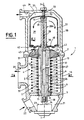
- the set of treatment of a fluid represented in the figures comprises a filter and a device centrifugation treatment, all contained in a single casing 1 in two parts 1 A, 1 B, assembled by bolts.
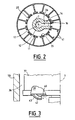
- Each filter element 5 comprises a plurality, twelve in the realization of Figure 2, of sectors angular 41 which, through orifices 25 formed in the 11 and in the bores 8, are likely successively to realize the communication of the interior space 27 delimited by the parts of the two sieve 6 of the sector concerned, with a conduit 26, which is provided in sector 14 of the fluid distributor 12 and which opens into the exhaust pipe 17, which is blind at the end of the fluid dispenser 12 opposite the partition 2.
- Said centrifuge chamber 37 is completely isolated of the chamber 36 for receiving the centrifuged fluid except the communication made by two 43, substantially diametrically opposed, of which the outlet orifices 42 are oriented substantially perpendicularly to a diameter passing through the axis 7, and in opposite directions.
- the fluid to be treated admitted in the room 21, fills the interior spaces 27 of all the sectors of the various filter elements 5, except the interior space of the sector 41 of each filter element which is momentarily isolated from other sectors 41 by the hollow sector 14, which communicates with the leads 26.
- This fluid to filter, contained in said spaces 27, passes through the screens 6 of said sectors, depositing thereon their inner faces the impurities it contains, and being received, free of impurities, in the room receiving 19 filtered fluid, ready to be reused.
- the pressure of the fluid already filtered contained in room 19 has the effect of causing the corresponding parts of the filter screens 6 by a part of said fluid, which makes it possible to take off periodically the impurities that have settled on the inner faces of the sieves and drive them into the exhaust duct 17.
- the engine 23 has the function to train step by step, sector 41 after sector 41, the distributor 12 in rotation so as to ensure the setting in periodic communication of each angular sector 41 of the various filter elements with the duct evacuation 17.
- This fluid loaded with impurities is conveyed directly through the exhaust ducts 17 and admission 28 to the enclosure 37, is received inside 39 of the centrifuge chamber, and, by centrifugation, is rid of its impurities.
- the purified fluid is then evacuated from the enclosure 37 through the nozzles 43 and being received in the chamber 36 from which it escapes to a user device, via an outlet fitting 44 which is provided with the part 1 B of the housing.
- the rotational drive of the centrifuge chamber 37 is made by the reaction effect, compared to the fluid contained in the enclosure 37, fluid that escapes from the inside 39 of the enclosure 37 through the conduits 42 of the nozzles 43.
- This Reaction effect is enough to cause rotation the centrifuge chamber at a rotational speed - of the order of 6000 revolutions / minute - at which occurs actually centrifugation.
- speed of rotation performed by the motor 23 is of the order of 2 at 3 rpm.
- the advantage of the described embodiment lies in the compactness and lightness of the whole; in the deletion possible leaks from the connections between filter and centrifuge, due to the deletion said external connections; in the deletion risks of breakage of the ducts external, which have been removed; and finally, in the reduction achieved in the manufacturing cost of the assembly.
- the invention is not limited to the realization of filters comprising disks or slabs of filter elements, but also covers the case of all other filters, such as, for example, those having cylindrical sieves.
- the motor 23, advantageously hydraulic type, can also, in variant, be of another type - electric for example.
- An application is the treatment of oils from lubrication of "diesel” engines, or purification certain fuels used by the said engines.
Landscapes
- Chemical & Material Sciences (AREA)
- Chemical Kinetics & Catalysis (AREA)
- Centrifugal Separators (AREA)
- Photosensitive Polymer And Photoresist Processing (AREA)
- Filtration Of Liquid (AREA)
- Filtering Of Dispersed Particles In Gases (AREA)
- Electrical Discharge Machining, Electrochemical Machining, And Combined Machining (AREA)
- Sampling And Sample Adjustment (AREA)
- Surgical Instruments (AREA)
Claims (3)
- Vorrichtung zur Behandlung einer Flüssigkeit, die einerseits mit einem Filter (4), bestehend aus mindestens einem Filterelement (5), und andererseits mit einer Zentrifugeneinrichtung versehen ist, die eine drehbare Umhüllung (37) mit einer Zuführungsleitung (28) und mindestens einer für die zentrifugierte Flüssigkeit vorgesehenen Austrittsdüse (43), die genau senkrecht zu einer durch die Rotationsachse (7) der Umhüllung (37) verlaufenden Graden gerichtet ist, und zwar dergestalt, dass die Umhüllung durch die Reaktion der aus der Austrittsdüse (43) austretenden Flüssigkeit in Rotation versetzt wird, wobei der Filter (4) zu jedem Filterelement (5) eine Reinigungseinrichtung aufweist, die mit einem drehbaren Verteiler (12-14) versehen ist, der durch einen Motor (23) um eine Rotationsachse gedreht wird und dazu bestimmt ist, einen Teil der Filterfläche periodisch zu isolieren, um dadurch die Reinigung durch die saubere Flüssigkeit zu ermöglichen, die im Gegenstrom durch jedes Filterelement (5) strömt und dann zu dessen Reinigung die Zentrifugeneinrichtung über eine Auslassleitung (17) speist, dadurch gekennzeichnet, dass der Filter (4) und die Zentrifugeneinrichtung in einem einzigen Gehäuse angeordnet sind, in welchem eine Kammer (19) zur Aufnahme der durch die Filterelemente des Filters gefilterten Flüssigkeit und eine Kammer zur Aufnahme der durch die Zentrifugeneinrichtung behandelten Flüssigkeit (36) untergebracht sind, wobei die Kammern jeweils durch eine flüssigkeitsdichte Trennwand (2) gegeneinander getrennt sind und sowohl den Filter als auch die Zentrifugeneinrichtung enthalten, dass die Trennwand eine Bohrung (13) aufweist, mit der der Verteiler in dichtem Kontakt steht, dass die Zentrifugeneinrichtung eine Zuführungsleitung (28) für die zu zentrifugierende Flüssigkeit aufweist, von der ein Ende in das offene Ende der Auslassleitung (17) des Verteilers eingesteckt ist, wobei die Auslassleitung direkt in die Zuführungsleitung (28) mündet, und dass die Zuführungsleitung eine Drehachse für die Zentrifugenumhüllung bildet, wobei Öffnungen (38) die Verbindung zwischen der Zuführungsleitung (28) und dem Innenraum der Zentrifugenumhüllung (37) herstellen.
- Behandlungsvorrichtung nach Anspruch 1, dadurch gekennzeichnet, dass das andere Ende (31) der Zuführungsleitung (28) fest (33-34) mit dem einzigen Gehäuse (1A-1B) verbunden ist.
- Behandlungsvorrichtung nach Anspruch 2, dadurch gekennzeichnet, dass das genannte andere Ende (31) der Zuführungsleitung (28) mittels eines Bolzens (33) befestigt ist, der außerdem die Dichtung (32) dieses anderen Endes realisiert.
Applications Claiming Priority (3)
| Application Number | Priority Date | Filing Date | Title |
|---|---|---|---|
| FR9412461A FR2725917B1 (fr) | 1994-10-19 | 1994-10-19 | Ensemble de traitement d'un fluide par filtration et centrifugation |
| FR9412461 | 1994-10-19 | ||
| PCT/FR1995/001382 WO1996012549A1 (fr) | 1994-10-19 | 1995-10-19 | Ensemble de traitement d'un fluide par filtration et centrifugation |
Publications (3)
| Publication Number | Publication Date |
|---|---|
| EP0787032A1 EP0787032A1 (de) | 1997-08-06 |
| EP0787032B1 EP0787032B1 (de) | 1999-12-22 |
| EP0787032B2 true EP0787032B2 (de) | 2005-11-02 |
Family
ID=9467988
Family Applications (1)
| Application Number | Title | Priority Date | Filing Date |
|---|---|---|---|
| EP95935987A Expired - Lifetime EP0787032B2 (de) | 1994-10-19 | 1995-10-19 | Vorrichtung zum behandlung von flüssigkeit mittels filtration und zentrifugation |
Country Status (13)
| Country | Link |
|---|---|
| US (1) | US5674392A (de) |
| EP (1) | EP0787032B2 (de) |
| JP (1) | JP3933197B2 (de) |
| KR (1) | KR100419939B1 (de) |
| CN (1) | CN1066976C (de) |
| AT (1) | ATE187897T1 (de) |
| DE (1) | DE69514117T3 (de) |
| ES (1) | ES2142495T5 (de) |
| FI (1) | FI971661A7 (de) |
| FR (1) | FR2725917B1 (de) |
| RU (1) | RU2142321C1 (de) |
| UA (1) | UA40659C2 (de) |
| WO (1) | WO1996012549A1 (de) |
Families Citing this family (35)
| Publication number | Priority date | Publication date | Assignee | Title |
|---|---|---|---|---|
| GB2311239B (en) * | 1996-03-19 | 2000-04-12 | Glacier Metal Co Ltd | Centrifugal liquid cleaning arrangement |
| FR2772636B1 (fr) * | 1997-12-19 | 2000-07-21 | Alfa Laval Moatti Snc | Ensemble pour l'epuration automatique d'un fluide pollue et procede de mise en oeuvre |
| US6019717A (en) * | 1998-08-19 | 2000-02-01 | Fleetguard, Inc. | Nozzle inlet enhancement for a high speed turbine-driven centrifuge |
| US6017300A (en) * | 1998-08-19 | 2000-01-25 | Fleetguard, Inc. | High performance soot removing centrifuge with impulse turbine |
| US6213929B1 (en) * | 1998-09-25 | 2001-04-10 | Analytical Engineering, Inc. | Motor driven centrifugal filter |
| FR2783722B1 (fr) * | 1998-09-28 | 2001-02-16 | Alfa Laval Moatti Snc | Ensemble de traitement d'un fluide avec controle de la temperature du fluide pollue au niveau de l'element filtrant |
| US6273031B1 (en) | 1998-12-11 | 2001-08-14 | Nelson Industries, Inc. | Clean lubricant circulation system |
| SE513440C2 (sv) | 1999-01-27 | 2000-09-11 | Alfa Laval Ab | Utlopp vid centrifugalseparator med reaktionsdriven rotor |
| GB2348830A (en) | 1999-04-12 | 2000-10-18 | Federal Mogul Eng Ltd | Liquid cleaning arrangement including duplex filter and centrifugal separator therefor |
| WO2001095994A1 (es) * | 2000-06-13 | 2001-12-20 | Benavides Terrazas Julian | Filtro ecológico lavable, no deshechable apra lubricantes y combustibles |
| WO2002012686A1 (en) * | 2000-08-05 | 2002-02-14 | Jong Chul Gu | Oil filter assembly |
| US6364822B1 (en) | 2000-12-07 | 2002-04-02 | Fleetguard, Inc. | Hero-turbine centrifuge with drainage enhancing baffle devices |
| US6709575B1 (en) | 2000-12-21 | 2004-03-23 | Nelson Industries, Inc. | Extended life combination filter |
| KR100474004B1 (ko) * | 2001-09-04 | 2005-03-07 | 구종철 | 오일 필터용 보조 장치 |
| US7081206B2 (en) * | 2002-07-31 | 2006-07-25 | Investors Precision Manufacturing, Inc. | Filter apparatus and method with centrifugal separator for removing contaminants from a fluid |
| US6893389B1 (en) | 2002-09-26 | 2005-05-17 | Fleetguard, Inc. | Disposable centrifuge with molded gear drive and impulse turbine |
| US6929596B2 (en) * | 2003-02-07 | 2005-08-16 | Fleetguard, Inc. | Centrifuge with separate hero turbine |
| US7235177B2 (en) * | 2003-04-23 | 2007-06-26 | Fleetguard, Inc. | Integral air/oil coalescer for a centrifuge |
| DE20312484U1 (de) * | 2003-08-13 | 2004-12-23 | Hengst Gmbh & Co.Kg | Vorrichtung zum Abtrennen von Verunreinigungen aus dem Schmieröl einer Brennkraftmaschine |
| FR2889666B1 (fr) * | 2005-08-11 | 2008-06-06 | Remy Nicolas Basile Mangano | Dispositif auto-nettoyant de filtration de fluide |
| DE202005020012U1 (de) * | 2005-12-22 | 2007-05-10 | Hengst Gmbh & Co.Kg | Zentrifuge zum Reinigen einer Flüssigkeit |
| US8021290B2 (en) * | 2007-11-26 | 2011-09-20 | Honeywell International Inc. | Oil centrifuge for extracting particulates from a fluid using centrifugal force |
| CN101543694B (zh) * | 2009-05-07 | 2011-01-26 | 洛阳华液通用机械成套制造有限公司 | 一种过滤、气分离机固液分离装置及工艺 |
| FR2964329B1 (fr) * | 2010-09-03 | 2012-09-28 | Alfa Laval Moatti | Filtre a decolmatage automatique |
| AU2011342730A1 (en) * | 2010-12-16 | 2013-07-04 | Amiad Water Systems Ltd. | Filtration system and components there for |
| US9561454B2 (en) * | 2012-10-09 | 2017-02-07 | Ovivo Inc. | Debris filter with splitter bar |
| US10245531B2 (en) * | 2015-06-17 | 2019-04-02 | Tm Industrial Supply, Inc. | High-efficiency automatic self-cleaning strainer |
| GB2539466B (en) * | 2015-06-17 | 2020-10-21 | Mann & Hummel Gmbh | Centrifugal separator |
| US20170218803A1 (en) * | 2016-02-03 | 2017-08-03 | Paccar Inc | Crankcase ventilation and centrifugal oil filter |
| CN106693514A (zh) * | 2017-03-07 | 2017-05-24 | 英泰流体控制科技(天津)有限公司 | 一种高效除渣设备及高效除渣系统 |
| CN109763873A (zh) * | 2019-03-12 | 2019-05-17 | 潍柴动力股份有限公司 | 一种发动机过滤系统及发动机 |
| CN112554992A (zh) * | 2020-11-04 | 2021-03-26 | 李冬菊 | 一种汽车机油净化用滤清器 |
| CN112474077B (zh) * | 2020-11-06 | 2022-06-28 | 重庆化工职业学院 | 一种化学化工固液分类回收处理装置及其使用方法 |
| RU205889U1 (ru) * | 2021-05-17 | 2021-08-11 | Федеральное государственное бюджетное образовательное учреждение высшего образования "Российский государственный аграрный университет - МСХА имени К.А. Тимирязева" (ФГБОУ ВО РГАУ - МСХА имени К.А. Тимирязева) | Самоочищающийся фильтр |
| US12422014B1 (en) * | 2025-03-14 | 2025-09-23 | Liquitech, Inc. | Low-friction wear surfaces for sediment filtration system hydraulic damper |
Citations (1)
| Publication number | Priority date | Publication date | Assignee | Title |
|---|---|---|---|---|
| DE3115716C2 (de) † | 1981-04-18 | 1993-09-09 | Boll & Kirch Filterbau Gmbh, 5014 Kerpen, De |
Family Cites Families (24)
| Publication number | Priority date | Publication date | Assignee | Title |
|---|---|---|---|---|
| GB723279A (en) * | 1952-10-02 | 1955-02-02 | Glacier Co Ltd | Improvements in or relating to centrifugal cleaners for separating impurities from liquids |
| GB731312A (en) * | 1953-03-03 | 1955-06-08 | Glacier Co Ltd | Improvements in or relating to centrifugal separators |
| GB876299A (en) * | 1958-12-11 | 1961-08-30 | Glacier Co Ltd | Filtering apparatus |
| US3231182A (en) * | 1963-06-28 | 1966-01-25 | Aero Flow Dynamics Inc | Centrifugal fluid purifier and filter bypass indicator combination |
| GB1089355A (en) * | 1965-09-22 | 1967-11-01 | Glacier Co Ltd | Centrifugal fluid cleaners |
| GB1239741A (de) * | 1967-06-05 | 1971-07-21 | ||
| US3944488A (en) * | 1971-05-19 | 1976-03-16 | Samuel Georges Moatti | Self-cleaning filter with motor incorporated therewith |
| SU563191A1 (ru) * | 1974-07-05 | 1977-06-30 | Предприятие П/Я А-3492 | Установка дл очистки масла в двигателе |
| SU636032A1 (ru) * | 1977-06-06 | 1978-12-05 | Предприятие П/Я В-2302 | Центрифуга дл очистки масла |
| US4221323A (en) * | 1978-12-07 | 1980-09-09 | The Glacier Metal Company Limited | Centrifugal filter with external service indicator |
| SU854454A1 (ru) * | 1979-07-12 | 1981-08-15 | Организация П/Я А-1742 | Центрифуга |
| CA1188662A (en) * | 1982-01-19 | 1985-06-11 | Henry W. Martin | Centrifugal separator |
| FR2534149B1 (fr) * | 1982-10-11 | 1987-11-06 | Moatti Georges | Filtre a fluide |
| SU1091946A1 (ru) * | 1982-11-25 | 1984-05-15 | Ордена Ленина,Ордена Трудового Красного Знамени Завод Транспортного Машиностроения Им.В.И.Ленина | Центрифуга дл очистки жидкости |
| FR2550463B1 (fr) * | 1983-08-08 | 1985-12-06 | Moatti Georges | Filtre muni d'un dispositif de decolmatage |
| US4557831A (en) * | 1984-04-12 | 1985-12-10 | Mack Trucks, Inc. | Centrifugal filter assembly |
| GB2160796B (en) * | 1984-05-04 | 1987-09-16 | Ae Plc | Oil cleaning assemblies for engines |
| GB2160449B (en) * | 1984-05-04 | 1988-09-21 | Ae Plc | Oil cleaning assemblies for engines |
| GB8504880D0 (en) * | 1985-02-26 | 1985-03-27 | Ae Plc | Disposable cartridges |
| SU1416189A1 (ru) * | 1985-06-06 | 1988-08-15 | Головное Специализированное Конструкторское Бюро По Двигателям Средней Мощности | Центрифуга дл очистки масла в двигател х внутреннего сгорани |
| SU1613175A1 (ru) * | 1987-12-07 | 1990-12-15 | Н.П.Мартынюк, В.Д.Шкилев, С.Н.Мартынюк и Л.Ф. Мартьшюк | Устройство дл оценки загр зненности центробежного маслоочистител двигател внутреннего сгорани |
| RU2035205C1 (ru) * | 1991-10-10 | 1995-05-20 | Евгений Алексеевич Шутков | Самоочищающийся фильтр |
| DE4306431C2 (de) * | 1993-03-02 | 2000-04-20 | Hengst Walter Gmbh & Co Kg | Vorrichtung zum Abtrennen von Verunreinigungen aus dem Schmieröl einer Brennkraftmaschine |
| RU2079340C1 (ru) * | 1994-07-28 | 1997-05-20 | Шутков Евгений Алексеевич | Способ "всн-1" очистки жидкости фильтром |
-
1994
- 1994-10-19 FR FR9412461A patent/FR2725917B1/fr not_active Expired - Lifetime
-
1995
- 1995-10-19 WO PCT/FR1995/001382 patent/WO1996012549A1/fr not_active Ceased
- 1995-10-19 JP JP51368596A patent/JP3933197B2/ja not_active Expired - Lifetime
- 1995-10-19 EP EP95935987A patent/EP0787032B2/de not_active Expired - Lifetime
- 1995-10-19 CN CN95195733A patent/CN1066976C/zh not_active Expired - Lifetime
- 1995-10-19 RU RU97107860A patent/RU2142321C1/ru active
- 1995-10-19 FI FI971661A patent/FI971661A7/fi unknown
- 1995-10-19 US US08/581,547 patent/US5674392A/en not_active Expired - Lifetime
- 1995-10-19 ES ES95935987T patent/ES2142495T5/es not_active Expired - Lifetime
- 1995-10-19 DE DE69514117T patent/DE69514117T3/de not_active Expired - Lifetime
- 1995-10-19 AT AT95935987T patent/ATE187897T1/de not_active IP Right Cessation
- 1995-10-19 KR KR1019970702543A patent/KR100419939B1/ko not_active Expired - Lifetime
- 1995-10-19 UA UA97041837A patent/UA40659C2/uk unknown
Patent Citations (1)
| Publication number | Priority date | Publication date | Assignee | Title |
|---|---|---|---|---|
| DE3115716C2 (de) † | 1981-04-18 | 1993-09-09 | Boll & Kirch Filterbau Gmbh, 5014 Kerpen, De |
Also Published As
| Publication number | Publication date |
|---|---|
| CN1066976C (zh) | 2001-06-13 |
| FR2725917B1 (fr) | 1997-11-21 |
| WO1996012549A1 (fr) | 1996-05-02 |
| DE69514117D1 (de) | 2000-01-27 |
| KR100419939B1 (ko) | 2004-05-24 |
| FI971661L (fi) | 1997-06-17 |
| RU2142321C1 (ru) | 1999-12-10 |
| FI971661A0 (fi) | 1997-04-18 |
| CN1161006A (zh) | 1997-10-01 |
| FI971661A7 (fi) | 1997-06-17 |
| DE69514117T3 (de) | 2006-07-27 |
| ATE187897T1 (de) | 2000-01-15 |
| DE69514117T2 (de) | 2000-07-20 |
| ES2142495T3 (es) | 2000-04-16 |
| EP0787032B1 (de) | 1999-12-22 |
| JPH11501248A (ja) | 1999-02-02 |
| ES2142495T5 (es) | 2006-05-16 |
| EP0787032A1 (de) | 1997-08-06 |
| JP3933197B2 (ja) | 2007-06-20 |
| KR970706881A (ko) | 1997-12-01 |
| UA40659C2 (uk) | 2001-08-15 |
| FR2725917A1 (fr) | 1996-04-26 |
| US5674392A (en) | 1997-10-07 |
Similar Documents
| Publication | Publication Date | Title |
|---|---|---|
| EP0787032B2 (de) | Vorrichtung zum behandlung von flüssigkeit mittels filtration und zentrifugation | |
| EP0062549B1 (de) | Vorrichtung zum Filtern von Fluiden und in dieser Vorrichtung durchgeführtes Verfahren | |
| EP0145552B1 (de) | Filter mit zwei unterschiedlichen Filteraufbauten | |
| CA2325722C (fr) | Dispositif de ventilation et moteur electrique de traction ferroviaire equipe d'un tel dispositif | |
| FR2933626A1 (fr) | Dispositif avec rotor a media coalesceur pour separer l'huile des gaz de carter d'un moteur a combustion interne. | |
| CH433194A (fr) | Dispositif de filtration mécanique multicellulaire à nettoyage automatique continu pour liquides sous pression | |
| CA2914936A1 (fr) | Boitier d'accessoires de turbomachine equipe d'un separateur air/huile | |
| EP0108665B1 (de) | Fluidumfilter | |
| FR2471813A1 (fr) | Dispositif de traitement de fluide | |
| WO2016120551A1 (fr) | Module de combustion a volume constant pour une turbomachine | |
| EP0519801B1 (de) | Fluid-Filter mit zwei Filtervorrichtungen | |
| FR2774137A1 (fr) | Dispositif de compression de gaz humide comportant un etage de compression/separation integrees | |
| EP0154098B1 (de) | Vorrichtung zur Gas-Flüssig-Trennung und ihre Anwendung bei der Entölung der Abluft aus den Lagergehäusen einer Turbomaschine | |
| EP0736691B1 (de) | Innenzahnradpumpe mit radialen Zuführungsröhren | |
| EP1289633A1 (de) | Filtervorrichtung mit integriertem kreislaufsystem | |
| FR2992693A1 (fr) | Pompe a engrenage interne double | |
| EP0149931B1 (de) | Filter mit mehreren Aufnahmekammern für das Filtrat und für eine andere Flüssigkeit welche durch den Rückstand den Hauptfiltrierung gebildet ist | |
| FR2503584A1 (fr) | Centrifugeuse pour l'epuration des liquides moteurs des systemes hydrauliques | |
| EP1752207B1 (de) | Filtervorrichtung mit integriertem Umlaufsystem und Umlaufpumpe | |
| CA2203007C (en) | Assembly for processing a fluid by filtration and centrifugation | |
| FR2694342A1 (fr) | Moteur à fluide sous pression comportant un ralentisseur interne et groupe d'entraînement en faisant application et comportant un organe d'immobilisation. | |
| FR3154439A1 (fr) | Ensemble pour boitier d’accessoires de turbomachine | |
| WO2005071297A1 (fr) | Distributeur rotatif fonctionnant en continu | |
| FR2551363A1 (fr) | Separateur centrifuge | |
| BE364721A (de) |
Legal Events
| Date | Code | Title | Description |
|---|---|---|---|
| PUAI | Public reference made under article 153(3) epc to a published international application that has entered the european phase |
Free format text: ORIGINAL CODE: 0009012 |
|
| 17P | Request for examination filed |
Effective date: 19970314 |
|
| AK | Designated contracting states |
Kind code of ref document: A1 Designated state(s): AT BE CH DE DK ES FR GB GR IE IT LI LU MC NL PT SE |
|
| 17Q | First examination report despatched |
Effective date: 19981008 |
|
| GRAG | Despatch of communication of intention to grant |
Free format text: ORIGINAL CODE: EPIDOS AGRA |
|
| GRAG | Despatch of communication of intention to grant |
Free format text: ORIGINAL CODE: EPIDOS AGRA |
|
| GRAH | Despatch of communication of intention to grant a patent |
Free format text: ORIGINAL CODE: EPIDOS IGRA |
|
| GRAH | Despatch of communication of intention to grant a patent |
Free format text: ORIGINAL CODE: EPIDOS IGRA |
|
| GRAA | (expected) grant |
Free format text: ORIGINAL CODE: 0009210 |
|
| AK | Designated contracting states |
Kind code of ref document: B1 Designated state(s): AT BE CH DE DK ES FR GB GR IE IT LI LU MC NL PT SE |
|
| PG25 | Lapsed in a contracting state [announced via postgrant information from national office to epo] |
Ref country code: SE Free format text: LAPSE BECAUSE OF NON-PAYMENT OF DUE FEES Effective date: 19991222 Ref country code: NL Free format text: LAPSE BECAUSE OF FAILURE TO SUBMIT A TRANSLATION OF THE DESCRIPTION OR TO PAY THE FEE WITHIN THE PRESCRIBED TIME-LIMIT Effective date: 19991222 Ref country code: GR Free format text: LAPSE BECAUSE OF NON-PAYMENT OF DUE FEES Effective date: 19991222 Ref country code: AT Free format text: LAPSE BECAUSE OF FAILURE TO SUBMIT A TRANSLATION OF THE DESCRIPTION OR TO PAY THE FEE WITHIN THE PRESCRIBED TIME-LIMIT Effective date: 19991222 |
|
| REF | Corresponds to: |
Ref document number: 187897 Country of ref document: AT Date of ref document: 20000115 Kind code of ref document: T |
|
| REG | Reference to a national code |
Ref country code: CH Ref legal event code: EP |
|
| REF | Corresponds to: |
Ref document number: 69514117 Country of ref document: DE Date of ref document: 20000127 |
|
| REG | Reference to a national code |
Ref country code: IE Ref legal event code: FG4D Free format text: FRENCH |
|
| ITF | It: translation for a ep patent filed | ||
| PG25 | Lapsed in a contracting state [announced via postgrant information from national office to epo] |
Ref country code: PT Free format text: LAPSE BECAUSE OF FAILURE TO SUBMIT A TRANSLATION OF THE DESCRIPTION OR TO PAY THE FEE WITHIN THE PRESCRIBED TIME-LIMIT Effective date: 20000322 Ref country code: DK Free format text: LAPSE BECAUSE OF FAILURE TO SUBMIT A TRANSLATION OF THE DESCRIPTION OR TO PAY THE FEE WITHIN THE PRESCRIBED TIME-LIMIT Effective date: 20000322 |
|
| REG | Reference to a national code |
Ref country code: ES Ref legal event code: FG2A Ref document number: 2142495 Country of ref document: ES Kind code of ref document: T3 |
|
| GBT | Gb: translation of ep patent filed (gb section 77(6)(a)/1977) |
Effective date: 20000419 |
|
| NLV1 | Nl: lapsed or annulled due to failure to fulfill the requirements of art. 29p and 29m of the patents act | ||
| PLBQ | Unpublished change to opponent data |
Free format text: ORIGINAL CODE: EPIDOS OPPO |
|
| PLBI | Opposition filed |
Free format text: ORIGINAL CODE: 0009260 |
|
| PG25 | Lapsed in a contracting state [announced via postgrant information from national office to epo] |
Ref country code: LU Free format text: LAPSE BECAUSE OF NON-PAYMENT OF DUE FEES Effective date: 20001019 |
|
| PLBF | Reply of patent proprietor to notice(s) of opposition |
Free format text: ORIGINAL CODE: EPIDOS OBSO |
|
| 26 | Opposition filed |
Opponent name: BOLL & KIRCH FILTERBAU GMBH Effective date: 20000831 |
|
| PG25 | Lapsed in a contracting state [announced via postgrant information from national office to epo] |
Ref country code: MC Free format text: THE PATENT HAS BEEN ANNULLED BY A DECISION OF A NATIONAL AUTHORITY Effective date: 20001031 Ref country code: LI Free format text: LAPSE BECAUSE OF NON-PAYMENT OF DUE FEES Effective date: 20001031 Ref country code: CH Free format text: LAPSE BECAUSE OF NON-PAYMENT OF DUE FEES Effective date: 20001031 |
|
| PG25 | Lapsed in a contracting state [announced via postgrant information from national office to epo] |
Ref country code: IE Free format text: LAPSE BECAUSE OF NON-PAYMENT OF DUE FEES Effective date: 20001116 |
|
| REG | Reference to a national code |
Ref country code: IE Ref legal event code: FD4D |
|
| PLBF | Reply of patent proprietor to notice(s) of opposition |
Free format text: ORIGINAL CODE: EPIDOS OBSO |
|
| RDAH | Patent revoked |
Free format text: ORIGINAL CODE: EPIDOS REVO |
|
| APAC | Appeal dossier modified |
Free format text: ORIGINAL CODE: EPIDOS NOAPO |
|
| APAE | Appeal reference modified |
Free format text: ORIGINAL CODE: EPIDOS REFNO |
|
| REG | Reference to a national code |
Ref country code: CH Ref legal event code: PL |
|
| APAC | Appeal dossier modified |
Free format text: ORIGINAL CODE: EPIDOS NOAPO |
|
| REG | Reference to a national code |
Ref country code: GB Ref legal event code: IF02 |
|
| APBU | Appeal procedure closed |
Free format text: ORIGINAL CODE: EPIDOSNNOA9O |
|
| PLAY | Examination report in opposition despatched + time limit |
Free format text: ORIGINAL CODE: EPIDOSNORE2 |
|
| PLBC | Reply to examination report in opposition received |
Free format text: ORIGINAL CODE: EPIDOSNORE3 |
|
| PLAT | Information related to reply to examination report in opposition deleted |
Free format text: ORIGINAL CODE: EPIDOSDORE3 |
|
| PLAY | Examination report in opposition despatched + time limit |
Free format text: ORIGINAL CODE: EPIDOSNORE2 |
|
| PLBC | Reply to examination report in opposition received |
Free format text: ORIGINAL CODE: EPIDOSNORE3 |
|
| PUAH | Patent maintained in amended form |
Free format text: ORIGINAL CODE: 0009272 |
|
| STAA | Information on the status of an ep patent application or granted ep patent |
Free format text: STATUS: PATENT MAINTAINED AS AMENDED |
|
| APAH | Appeal reference modified |
Free format text: ORIGINAL CODE: EPIDOSCREFNO |
|
| 27A | Patent maintained in amended form |
Effective date: 20051102 |
|
| AK | Designated contracting states |
Kind code of ref document: B2 Designated state(s): AT BE CH DE DK ES FR GB GR IE IT LI LU MC NL PT SE |
|
| REG | Reference to a national code |
Ref country code: CH Ref legal event code: AEN Free format text: MAINTIEN DU BREVET DONT L'ETENDUE A ETE MODIFIEE |
|
| GBTA | Gb: translation of amended ep patent filed (gb section 77(6)(b)/1977) | ||
| REG | Reference to a national code |
Ref country code: ES Ref legal event code: DC2A Date of ref document: 20060124 Kind code of ref document: T5 |
|
| PGFP | Annual fee paid to national office [announced via postgrant information from national office to epo] |
Ref country code: ES Payment date: 20140911 Year of fee payment: 20 |
|
| PGFP | Annual fee paid to national office [announced via postgrant information from national office to epo] |
Ref country code: GB Payment date: 20141015 Year of fee payment: 20 Ref country code: FR Payment date: 20141008 Year of fee payment: 20 Ref country code: DE Payment date: 20141014 Year of fee payment: 20 |
|
| PGFP | Annual fee paid to national office [announced via postgrant information from national office to epo] |
Ref country code: IT Payment date: 20141010 Year of fee payment: 20 |
|
| PGFP | Annual fee paid to national office [announced via postgrant information from national office to epo] |
Ref country code: BE Payment date: 20141013 Year of fee payment: 20 |
|
| REG | Reference to a national code |
Ref country code: DE Ref legal event code: R071 Ref document number: 69514117 Country of ref document: DE |
|
| REG | Reference to a national code |
Ref country code: GB Ref legal event code: PE20 Expiry date: 20151018 |
|
| REG | Reference to a national code |
Ref country code: ES Ref legal event code: FD2A Effective date: 20160126 |
|
| PG25 | Lapsed in a contracting state [announced via postgrant information from national office to epo] |
Ref country code: GB Free format text: LAPSE BECAUSE OF EXPIRATION OF PROTECTION Effective date: 20151018 |
|
| PG25 | Lapsed in a contracting state [announced via postgrant information from national office to epo] |
Ref country code: ES Free format text: LAPSE BECAUSE OF EXPIRATION OF PROTECTION Effective date: 20151020 |