EP0787423A1 - Carter de tondeuse et dispositif soufflant - Google Patents
Carter de tondeuse et dispositif soufflant Download PDFInfo
- Publication number
- EP0787423A1 EP0787423A1 EP97100732A EP97100732A EP0787423A1 EP 0787423 A1 EP0787423 A1 EP 0787423A1 EP 97100732 A EP97100732 A EP 97100732A EP 97100732 A EP97100732 A EP 97100732A EP 0787423 A1 EP0787423 A1 EP 0787423A1
- Authority
- EP
- European Patent Office
- Prior art keywords
- housing
- blower
- mower
- mower housing
- fan
- Prior art date
- Legal status (The legal status is an assumption and is not a legal conclusion. Google has not performed a legal analysis and makes no representation as to the accuracy of the status listed.)
- Granted
Links
- 239000000463 material Substances 0.000 description 5
- 239000002184 metal Substances 0.000 description 5
- 244000025254 Cannabis sativa Species 0.000 description 3
- 238000004140 cleaning Methods 0.000 description 2
- 238000012423 maintenance Methods 0.000 description 2
- 238000007664 blowing Methods 0.000 description 1
Images



Classifications
-
- A—HUMAN NECESSITIES
- A01—AGRICULTURE; FORESTRY; ANIMAL HUSBANDRY; HUNTING; TRAPPING; FISHING
- A01D—HARVESTING; MOWING
- A01D43/00—Mowers combined with apparatus performing additional operations while mowing
- A01D43/06—Mowers combined with apparatus performing additional operations while mowing with means for collecting, gathering or loading mown material
- A01D43/077—Mowers combined with apparatus performing additional operations while mowing with means for collecting, gathering or loading mown material with auxiliary means, e.g. fans, for transporting the mown crop
-
- A—HUMAN NECESSITIES
- A01—AGRICULTURE; FORESTRY; ANIMAL HUSBANDRY; HUNTING; TRAPPING; FISHING
- A01D—HARVESTING; MOWING
- A01D2101/00—Lawn-mowers
-
- A—HUMAN NECESSITIES
- A01—AGRICULTURE; FORESTRY; ANIMAL HUSBANDRY; HUNTING; TRAPPING; FISHING
- A01D—HARVESTING; MOWING
- A01D34/00—Mowers; Mowing apparatus of harvesters
- A01D34/01—Mowers; Mowing apparatus of harvesters characterised by features relating to the type of cutting apparatus
- A01D34/412—Mowers; Mowing apparatus of harvesters characterised by features relating to the type of cutting apparatus having rotating cutters
- A01D34/63—Mowers; Mowing apparatus of harvesters characterised by features relating to the type of cutting apparatus having rotating cutters having cutters rotating about a vertical axis
Definitions
- the invention relates to a mower deck and blower that is horizontally pivotably connected to the mower deck, is provided with a component that can be driven from the mower deck via a belt drive, is adjustable between an operating position on the mower deck and a second position pivoted away from the mower deck, and can be locked in the operating position is.
- Such a combination of devices is known from document US-A-5 240 461.
- a mower is usually suspended under a lawn tractor, with the mower blowing out the cut material laterally. If the material is then not to be placed on the previously cut lawn, it must be collected, for example in a container attached to or carried by the lawn tractor. The material gets into this through an emptying pipe, which connects to a blower, which in turn is provided at the discharge opening of the mower.
- the fan wheel belonging to the fan is driven by a drive pulley on the mower via a belt. The belt tension is maintained via a tension pulley.
- the tensioning pulley itself is adjusted when a hand lever is released, via which a lock for the blower is released, such that the belt is no longer tensioned and can be removed from the drive pulley.
- the belt must be removed when the blower is pivoted into its second position, since the articulation point of the blower is at one end of the blower housing and the belt is guided into the blower housing at the other end thereof. If the blower housing is now to be cleaned, the belt must first be removed so that the blower can be adjusted to its second position. When working in wet or long grass, such mowers tend to become clogged and need to be cleared. The fan must be unlocked and moved to its second position.
- the invention provides that the locking device has a resilient arm which can be braced with a hook part.
- the arm is pivotally mounted on the blower housing between its ends, the hook part being arranged on the blower housing and an eyelet being provided on the mower housing, in which one end of the arm, which is designed as a catch hook, engages in the operating position.
- blower housing is provided in a region remote from the lock with a sleeve which can be plugged onto a support pin on the mower housing.
- the fan housing is in relation to the direction of travel Area of its rear end pivotally connected to the mower housing, the locking being provided at the front end.
- a pivotable fan 10 can be seen in a perspective view, which is connected to a mower housing 12.
- the inlet opening 14 of the blower 10 is brought into register with the outlet opening 16 of the mower housing 12 in the operating position, the mower housing being typically mounted below a small tractor or below a similar vehicle.
- the blower 10 can be detachably connected to the mower housing 12 and has a lock 18 at its front end 20, via which the blower 10 can be locked to the mower housing 12.
- the blower 10 is provided with an outlet 24, to which an emptying pipe 26 can be connected, via which material conveyed by the blower 10 can get into a collecting truck pulled by the small tractor.
- a collection container can of course also be connected to the rear of the tractor.
- the blower 10 is also equipped on its outside with a cover or a covering 28, which serves to cover and protect the drive components provided there.
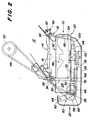
- FIG. 2 to 4 show the fan in different positions seen from above, with FIG. 2 showing the closed position.
- a frame part 30 serving for connection to the mower housing with two support legs 32 and 34 and a sleeve 36 (see FIG. 5).
- the frame part is pivotally connected to the mower housing via the sleeve, for which purpose the sleeve 36 is pushed onto a support pin 38 provided on the mower housing 12.
- the L-shaped frame part 30 is connected, for example welded, to a plate 40, which in turn carries the blower housing 42.
- the frame part 30 is also provided with a boom 44 which carries a pulley 46, which serves to change the direction of a drive belt 48 when coming from the deck deck is deflected to a pulley 52, which with the Blower wheel 54 is drivingly connected.
- a tensioning disk 56 is also still supported at the outer end of the arm 44.
- the tensioning disk 56 is received by one end part 58 of a lever part 60, the other end part 62 of which is connected to a swivel part 64 which is mounted on the arm 44.
- a spring 66 tries to turn the lever part clockwise with reference to FIG. 2 and thus also the tensioning disk in the same direction of rotation about the axis of the swivel part 64.
- the lever part 60 is still provided at its end part 58 with a protruding eyelet 68 which has an opening.
- a sliding part 70, to which a rod 72 belongs, is anchored at one end in this opening.
- the rod 72 is adjustable in a slot 74 in a tab 76, which can best be seen from FIGS. 6 and 7.
- the rod 72 is provided at its other end with an upwardly projecting handle 78 which protrudes through an opening 80 in the casing 28 which can be seen in FIG. 1.
- the slot 74 is formed like a keyhole and is therefore provided with a thinner upper section 82 through which the rod 72 can also pass.
- the rod is also provided with a stop 84 which surrounds the rod and has an outer diameter which is greater than the slot width in the section 82.
- the spring 66 can be used to pull the stop against the tab 76, the slot opening of which in the lower region is such is that it lets the attack go through.
- the lock 18 provided at the front end 20 of the blower in the preferred embodiment consists essentially of a resilient metal rod 86 in the form of an arm bent several times. 1, 2 and 3 it can be seen that the rod 86 is pivotally connected to the blower housing 42 at the point 88 and has a hook part 90 at its front end or the mower housing end which engages in the opening of an eyelet 92 should, which is provided on the mower housing 12.
- the the other end of the metal rod 86 is long enough and thus also flexible enough to be inserted into the catch recess of a catch hook 94 projecting downwards, which in turn is provided on the blower housing 42. The lock is thus guided around the front end of the fan.
- the blower In the operating position of the blower 10, as can be seen from FIG. 1, the blower is connected to the outlet 16 of the mower housing, which takes place at the front end 20 via the lock 18.
- the material cut by the knives rotating in the mower housing is thrown through the outlet opening 16 in the mower housing into the inlet opening 14 in the blower 10 and into the blower wheel space 96 of the blower, where it is rotated clockwise with reference to FIG revolving impeller is further conveyed through the outlet 24 of the fan.
- the belt 48 driving the impeller 54 is driven by the drive pulley 50 provided on the top of the mower deck.
- the belt 48 is then passed around the belt deflecting pulley 46, which is provided at the rear end 22 of the fan, and further around the pulley 52 on the impeller and back and around the tension pulley 56 until finally to the drive pulley.
- the belt tension required for driving the impeller is generated by the tensioning pulley which, with reference to FIGS. 2 and 3, wants to rotate clockwise about its axis of rotation or its pivoting part 64 via the spring 66.
- the rod 72 In operational use and when the belt is tensioned, the rod 72 is located in the lower and larger hole area 98 of the slot 74 in the tab 76, the stop 84 being located to the left of the tab 76, as can be seen from FIG. 4.
- the operator must first stop the small tractor to clean the blower and drive to the blower interrupt.
- the drive to the mower must also be interrupted for safety reasons.
- the operator can then pivot the blower into an open or accessible position, as can be seen in FIG. 3.
- the operator first releases the handle 100 of the metal bar 86 from the catch hook 94 by pushing the handle inwards and then downwards.
- the hook part 90 at the other end of the metal rod also emerges from the opening in the eyelet 92 on the mower housing 12.
- the front end 20 of the blower 10 can then in about the axis of the support pin 38 3, in which the interior of the blower chamber 96 of the blower or the outlet 16 of the mower housing are easily accessible.
- the operator also wants to relax the drive belt for the cleaning work, he moves the rod 72 from the large slot opening 98 into the narrower upper part 82 of the slot 74 in the tab 76. Since the rod 72 with the lever part 60, which is due to the spring action wants to turn clockwise, is connected, it is adjusted accordingly by the lever part. On the other hand, it is also possible that the operator may move the rod from its position according to FIG. 4 to its position according to FIG. 5 after the blower has been opened by pulling the handle 78 forward, the stop 84 through the large one Slot opening 98 in tab 76 passes through. The rod is then adjusted into the upper and narrower section 82 of the slot 74, after which the spring 66 acting on the lever part can pull the stop 84 against the tab to abut.
- blower Since the blower is horizontally pivotably connected to the mower housing at its rear left end and can be locked to the mower housing at its front end by means of a quick-release fastener, it can be easily opened for clogging for cleaning purposes.
- the drive belt is easy to relax and can also be easily removed if desired. The same also applies to the dismantling of the entire fan, since it is only attached to the support pin 38.
Landscapes
- Life Sciences & Earth Sciences (AREA)
- Environmental Sciences (AREA)
- Harvester Elements (AREA)
Applications Claiming Priority (2)
| Application Number | Priority Date | Filing Date | Title |
|---|---|---|---|
| US595686 | 1990-10-09 | ||
| US08/595,686 US5669211A (en) | 1996-02-02 | 1996-02-02 | Pivotal mounting for auxiliary blower |
Publications (2)
| Publication Number | Publication Date |
|---|---|
| EP0787423A1 true EP0787423A1 (fr) | 1997-08-06 |
| EP0787423B1 EP0787423B1 (fr) | 2000-05-10 |
Family
ID=24384254
Family Applications (1)
| Application Number | Title | Priority Date | Filing Date |
|---|---|---|---|
| EP97100732A Expired - Lifetime EP0787423B1 (fr) | 1996-02-02 | 1997-01-17 | Carter de tondeuse et dispositif soufflant |
Country Status (4)
| Country | Link |
|---|---|
| US (1) | US5669211A (fr) |
| EP (1) | EP0787423B1 (fr) |
| CA (1) | CA2191989C (fr) |
| DE (1) | DE59701612D1 (fr) |
Cited By (1)
| Publication number | Priority date | Publication date | Assignee | Title |
|---|---|---|---|---|
| EP1483954A1 (fr) * | 2003-06-02 | 2004-12-08 | Fritz Sperber GmbH & Co. | Unité d'entrainement pour un dispositif de transport de matériaux, notamment pour une machine de ramassage des herbes coupés |
Families Citing this family (4)
| Publication number | Priority date | Publication date | Assignee | Title |
|---|---|---|---|---|
| US10694673B2 (en) | 2017-03-13 | 2020-06-30 | Ariens Company | Lawn mower including an inclined blower |
| US10383280B2 (en) | 2017-09-11 | 2019-08-20 | Deer & Company | Mower deck discharge chute with drive belt tunnel |
| US20220287238A1 (en) * | 2021-03-10 | 2022-09-15 | Techtronic Cordless Gp | Lawnmowers |
| US20240215487A1 (en) * | 2022-12-29 | 2024-07-04 | Kubota Corporation | Discharge control system and method for wheeled lawn care machine |
Citations (8)
| Publication number | Priority date | Publication date | Assignee | Title |
|---|---|---|---|---|
| FR2108333A5 (fr) * | 1970-09-24 | 1972-05-19 | Deere & Co | |
| US4010518A (en) * | 1975-06-16 | 1977-03-08 | The Wiremold Company | Clamp for flexible duct |
| US4735037A (en) * | 1986-07-14 | 1988-04-05 | Deere & Company | Quick detachable auxiliary blower for mower deck |
| JPS6430509A (en) * | 1987-07-27 | 1989-02-01 | Kubota Ltd | Cutting side-delivery rake |
| GB2223660A (en) * | 1988-10-17 | 1990-04-18 | Honda Motor Co Ltd | Lawn mower with blower |
| JPH0538219A (ja) * | 1991-08-08 | 1993-02-19 | Iseki & Co Ltd | トラクタモーアのコレクター |
| US5240461A (en) | 1992-07-01 | 1993-08-31 | Deere & Company | Blower mounting with belt tensioner |
| FR2732546A1 (fr) * | 1995-04-04 | 1996-10-11 | Honda Motor Co Ltd | Appareil de transport de gazon tondu d'une tondeuse a gazon |
Family Cites Families (6)
| Publication number | Priority date | Publication date | Assignee | Title |
|---|---|---|---|---|
| US2856785A (en) * | 1954-10-01 | 1958-10-21 | Ray N Steele | Bracket for mounting an auxiliary generator on the regular generator of an engine |
| US4693063A (en) * | 1985-01-17 | 1987-09-15 | Hoepfner Thomas L | Material collection apparatus |
| JPH0513144Y2 (fr) * | 1987-08-06 | 1993-04-07 | ||
| US5018344A (en) * | 1988-08-24 | 1991-05-28 | Kubota, Ltd. | Lawn mower with blower unit |
| US5254046A (en) * | 1992-06-26 | 1993-10-19 | Deere & Company | Belt retainer |
| JPH07155042A (ja) * | 1993-12-09 | 1995-06-20 | Kubota Corp | 草刈機 |
-
1996
- 1996-02-02 US US08/595,686 patent/US5669211A/en not_active Expired - Lifetime
- 1996-12-03 CA CA002191989A patent/CA2191989C/fr not_active Expired - Fee Related
-
1997
- 1997-01-17 DE DE59701612T patent/DE59701612D1/de not_active Expired - Fee Related
- 1997-01-17 EP EP97100732A patent/EP0787423B1/fr not_active Expired - Lifetime
Patent Citations (8)
| Publication number | Priority date | Publication date | Assignee | Title |
|---|---|---|---|---|
| FR2108333A5 (fr) * | 1970-09-24 | 1972-05-19 | Deere & Co | |
| US4010518A (en) * | 1975-06-16 | 1977-03-08 | The Wiremold Company | Clamp for flexible duct |
| US4735037A (en) * | 1986-07-14 | 1988-04-05 | Deere & Company | Quick detachable auxiliary blower for mower deck |
| JPS6430509A (en) * | 1987-07-27 | 1989-02-01 | Kubota Ltd | Cutting side-delivery rake |
| GB2223660A (en) * | 1988-10-17 | 1990-04-18 | Honda Motor Co Ltd | Lawn mower with blower |
| JPH0538219A (ja) * | 1991-08-08 | 1993-02-19 | Iseki & Co Ltd | トラクタモーアのコレクター |
| US5240461A (en) | 1992-07-01 | 1993-08-31 | Deere & Company | Blower mounting with belt tensioner |
| FR2732546A1 (fr) * | 1995-04-04 | 1996-10-11 | Honda Motor Co Ltd | Appareil de transport de gazon tondu d'une tondeuse a gazon |
Non-Patent Citations (2)
| Title |
|---|
| PATENT ABSTRACTS OF JAPAN vol. 013, no. 211 (C - 597) 17 May 1989 (1989-05-17) * |
| PATENT ABSTRACTS OF JAPAN vol. 017, no. 333 (C - 1074) 24 June 1993 (1993-06-24) * |
Cited By (1)
| Publication number | Priority date | Publication date | Assignee | Title |
|---|---|---|---|---|
| EP1483954A1 (fr) * | 2003-06-02 | 2004-12-08 | Fritz Sperber GmbH & Co. | Unité d'entrainement pour un dispositif de transport de matériaux, notamment pour une machine de ramassage des herbes coupés |
Also Published As
| Publication number | Publication date |
|---|---|
| US5669211A (en) | 1997-09-23 |
| CA2191989C (fr) | 2000-03-14 |
| EP0787423B1 (fr) | 2000-05-10 |
| DE59701612D1 (de) | 2000-06-15 |
| CA2191989A1 (fr) | 1997-08-03 |
Similar Documents
| Publication | Publication Date | Title |
|---|---|---|
| DE69806851T2 (de) | Selbstfahrender Rasenmäher mit Grasfangbehälter | |
| EP0787424B1 (fr) | Carter de tondeuse et dispositif soufflant | |
| DE69917748T2 (de) | Kombination faden- und messerschneider mit gebläse-hilfsfunktion | |
| DE19748475C2 (de) | Mähwerk für Rasenmäher | |
| DE2926725A1 (de) | Kuehlluftfilter fuer den brennkraftmotor, insbesondere fuer selbstfahrende landwirtschaftliche maschinen | |
| EP1151654B1 (fr) | Machine de récolte en particulier faucheuse-hacheuse automotrice | |
| EP0071721A2 (fr) | Tondeuse à gazon avec dispositif de ramassage | |
| DE60210169T2 (de) | Mähwerk und Fahrzeug zur Rasen-, Garten- und Grundstückspflege | |
| EP0074533B1 (fr) | Chariot pour brins | |
| EP0568947B1 (fr) | Machine à couper et/ou ramasser munie d'un volet de sécurité monté à pivotement sur une goulotte de décharge | |
| EP0576962B1 (fr) | Dispositif et accessoire connecté de façon pivotante comprenant un élément entraîné par le dispositif | |
| DE2636488C2 (fr) | ||
| EP0674983A1 (fr) | Dispositif de granulation pour matériau filiforme | |
| DE69716749T2 (de) | Blas- und saugvorrichtung | |
| EP0787423B1 (fr) | Carter de tondeuse et dispositif soufflant | |
| DE2810176C2 (de) | Mähdrescher mit Anbauhäcksler | |
| DE3611511C2 (fr) | ||
| EP0997065B1 (fr) | Récipient collecteur et appareil de travail | |
| DE10228880B4 (de) | Mähgerät zur Rasen- und Landschaftswiesenpflege mit einer Vorrichtung zur Aufnahme und Zerkleinerung von Mähgut | |
| DE69611629T2 (de) | Rasenmäher mit einem gelenkig verbundenen Grasabführkanal | |
| EP0254657A1 (fr) | Tondeuse à gazon munie d'un siège pour conducteur | |
| DE1482036A1 (de) | Stuetze fuer einen an einen Rasenmaeher anzubringenden Grasfaengersack | |
| EP1561372B1 (fr) | Appareil de traitement de gazon guidé manuellement | |
| DE69011865T2 (de) | Reinigungsvorrichtung für ein Filterelement. | |
| DE2950709A1 (de) | Rasenmaeher |
Legal Events
| Date | Code | Title | Description |
|---|---|---|---|
| PUAI | Public reference made under article 153(3) epc to a published international application that has entered the european phase |
Free format text: ORIGINAL CODE: 0009012 |
|
| 17P | Request for examination filed |
Effective date: 19970604 |
|
| AK | Designated contracting states |
Kind code of ref document: A1 Designated state(s): DE FR GB IE IT |
|
| GRAG | Despatch of communication of intention to grant |
Free format text: ORIGINAL CODE: EPIDOS AGRA |
|
| 17Q | First examination report despatched |
Effective date: 19990730 |
|
| RAP1 | Party data changed (applicant data changed or rights of an application transferred) |
Owner name: DEERE & COMPANY |
|
| GRAG | Despatch of communication of intention to grant |
Free format text: ORIGINAL CODE: EPIDOS AGRA |
|
| GRAG | Despatch of communication of intention to grant |
Free format text: ORIGINAL CODE: EPIDOS AGRA |
|
| GRAH | Despatch of communication of intention to grant a patent |
Free format text: ORIGINAL CODE: EPIDOS IGRA |
|
| GRAH | Despatch of communication of intention to grant a patent |
Free format text: ORIGINAL CODE: EPIDOS IGRA |
|
| GRAA | (expected) grant |
Free format text: ORIGINAL CODE: 0009210 |
|
| AK | Designated contracting states |
Kind code of ref document: B1 Designated state(s): DE FR GB IE IT |
|
| RIC1 | Information provided on ipc code assigned before grant |
Free format text: 7A 01D 34/71 A |
|
| REG | Reference to a national code |
Ref country code: IE Ref legal event code: FG4D Free format text: GERMAN |
|
| REF | Corresponds to: |
Ref document number: 59701612 Country of ref document: DE Date of ref document: 20000615 |
|
| GBT | Gb: translation of ep patent filed (gb section 77(6)(a)/1977) |
Effective date: 20000602 |
|
| ITF | It: translation for a ep patent filed | ||
| ET | Fr: translation filed | ||
| PLBE | No opposition filed within time limit |
Free format text: ORIGINAL CODE: 0009261 |
|
| STAA | Information on the status of an ep patent application or granted ep patent |
Free format text: STATUS: NO OPPOSITION FILED WITHIN TIME LIMIT |
|
| 26N | No opposition filed | ||
| REG | Reference to a national code |
Ref country code: GB Ref legal event code: IF02 |
|
| PGFP | Annual fee paid to national office [announced via postgrant information from national office to epo] |
Ref country code: IE Payment date: 20050128 Year of fee payment: 9 |
|
| PG25 | Lapsed in a contracting state [announced via postgrant information from national office to epo] |
Ref country code: IE Free format text: LAPSE BECAUSE OF NON-PAYMENT OF DUE FEES Effective date: 20060117 |
|
| PGFP | Annual fee paid to national office [announced via postgrant information from national office to epo] |
Ref country code: IT Payment date: 20060131 Year of fee payment: 10 |
|
| REG | Reference to a national code |
Ref country code: IE Ref legal event code: MM4A |
|
| PGFP | Annual fee paid to national office [announced via postgrant information from national office to epo] |
Ref country code: DE Payment date: 20071220 Year of fee payment: 12 |
|
| PGFP | Annual fee paid to national office [announced via postgrant information from national office to epo] |
Ref country code: FR Payment date: 20080117 Year of fee payment: 12 |
|
| PG25 | Lapsed in a contracting state [announced via postgrant information from national office to epo] |
Ref country code: IT Free format text: LAPSE BECAUSE OF NON-PAYMENT OF DUE FEES Effective date: 20070117 |
|
| PG25 | Lapsed in a contracting state [announced via postgrant information from national office to epo] |
Ref country code: DE Free format text: LAPSE BECAUSE OF NON-PAYMENT OF DUE FEES Effective date: 20090801 |
|
| REG | Reference to a national code |
Ref country code: FR Ref legal event code: ST Effective date: 20091030 |
|
| PG25 | Lapsed in a contracting state [announced via postgrant information from national office to epo] |
Ref country code: FR Free format text: LAPSE BECAUSE OF NON-PAYMENT OF DUE FEES Effective date: 20090202 |
|
| PGFP | Annual fee paid to national office [announced via postgrant information from national office to epo] |
Ref country code: GB Payment date: 20140127 Year of fee payment: 18 |
|
| GBPC | Gb: european patent ceased through non-payment of renewal fee |
Effective date: 20150117 |
|
| PG25 | Lapsed in a contracting state [announced via postgrant information from national office to epo] |
Ref country code: GB Free format text: LAPSE BECAUSE OF NON-PAYMENT OF DUE FEES Effective date: 20150117 |