EP0787455A1 - Dispositif à chauffer des plats par induction - Google Patents
Dispositif à chauffer des plats par induction Download PDFInfo
- Publication number
- EP0787455A1 EP0787455A1 EP96109848A EP96109848A EP0787455A1 EP 0787455 A1 EP0787455 A1 EP 0787455A1 EP 96109848 A EP96109848 A EP 96109848A EP 96109848 A EP96109848 A EP 96109848A EP 0787455 A1 EP0787455 A1 EP 0787455A1
- Authority
- EP
- European Patent Office
- Prior art keywords
- heating
- housing part
- housing
- trays
- floors
- Prior art date
- Legal status (The legal status is an assumption and is not a legal conclusion. Google has not performed a legal analysis and makes no representation as to the accuracy of the status listed.)
- Withdrawn
Links
- 238000010438 heat treatment Methods 0.000 title claims abstract description 102
- 235000013305 food Nutrition 0.000 title abstract description 15
- 230000001939 inductive effect Effects 0.000 claims description 9
- 238000010792 warming Methods 0.000 claims description 4
- 210000002105 tongue Anatomy 0.000 claims description 3
- 238000013021 overheating Methods 0.000 abstract 1
- 230000006698 induction Effects 0.000 description 7
- 238000003032 molecular docking Methods 0.000 description 4
- 229910052751 metal Inorganic materials 0.000 description 3
- 239000002184 metal Substances 0.000 description 3
- 230000006978 adaptation Effects 0.000 description 2
- 238000004140 cleaning Methods 0.000 description 2
- 238000001816 cooling Methods 0.000 description 2
- 238000005192 partition Methods 0.000 description 2
- 240000008415 Lactuca sativa Species 0.000 description 1
- 230000033228 biological regulation Effects 0.000 description 1
- 235000011850 desserts Nutrition 0.000 description 1
- 230000000694 effects Effects 0.000 description 1
- 238000010616 electrical installation Methods 0.000 description 1
- 235000021268 hot food Nutrition 0.000 description 1
- 238000009413 insulation Methods 0.000 description 1
- 238000000034 method Methods 0.000 description 1
- 238000000465 moulding Methods 0.000 description 1
- 235000012045 salad Nutrition 0.000 description 1
- 229910052709 silver Inorganic materials 0.000 description 1
- 239000004332 silver Substances 0.000 description 1
- 238000005406 washing Methods 0.000 description 1
Images
Classifications
-
- H—ELECTRICITY
- H05—ELECTRIC TECHNIQUES NOT OTHERWISE PROVIDED FOR
- H05B—ELECTRIC HEATING; ELECTRIC LIGHT SOURCES NOT OTHERWISE PROVIDED FOR; CIRCUIT ARRANGEMENTS FOR ELECTRIC LIGHT SOURCES, IN GENERAL
- H05B6/00—Heating by electric, magnetic or electromagnetic fields
- H05B6/02—Induction heating
- H05B6/10—Induction heating apparatus, other than furnaces, for specific applications
- H05B6/12—Cooking devices
- H05B6/129—Cooking devices induction ovens
-
- A—HUMAN NECESSITIES
- A47—FURNITURE; DOMESTIC ARTICLES OR APPLIANCES; COFFEE MILLS; SPICE MILLS; SUCTION CLEANERS IN GENERAL
- A47J—KITCHEN EQUIPMENT; COFFEE MILLS; SPICE MILLS; APPARATUS FOR MAKING BEVERAGES
- A47J39/00—Heat-insulated warming chambers; Cupboards with heating arrangements for warming kitchen utensils
- A47J39/006—Heat-insulated warming chambers; Cupboards with heating arrangements for warming kitchen utensils for either storing and preparing or for preparing food on serving trays, e.g. heating, thawing, preserving
Definitions
- the invention relates to a device for inductive heating or warming up of food, which is portioned in at least some areas of electrically conductive vessels (so-called induction dishes), each of which is placed on a tray at a predetermined heating point, in particular.
- induction dishes electrically conductive vessels
- for warming up patient menus in hospitals with several shelves, one above the other and, if necessary, juxtaposed in a substantially rectangular housing, essentially horizontal heating shelves, each with a high-frequency heating station assigned to a heating point of an assigned tray
- Have alternating current acted on coil the trays covered with vessels each on support means in the housing are to be supported that their heating points in the heating position entered are in each case essentially aligned with a heating point of a heating floor.
- the food to be served esp. Menus, i. a. already in the kitchen area, on plates, in bowls and the like. portioned.
- the food containers intended for a person to be cared for are placed on a tray and a number of, for example, twenty filled trays are placed one above the other and, if necessary, next to one another in a so-called tray trolley.
- the tray trolley provided with occupied trays are then or the like in each case from the kitchen area to the relevant infirmary. proceed where the trays are removed one by one and handed over to the people to be cared for.
- Insulating trays are often used to counteract excessive cooling of hot food. However, it has been shown that this measure, in particular With relatively long transport routes, it is often not sufficient to keep food sufficiently warm until it is consumed.
- tray trolleys Since too much cooled food leads to a loss of quality and too much cooling also violates relevant recommendations or regulations, or the like, a minimum temperature of 65 ° C when handed over to the patient concerned. prescribe, electrically heated tray trolleys have already become known in which food intended for warm consumption is to be kept specifically warm or are to be warmed up. Such tray trolleys cannot be designed in the manner of heating ovens, which heat the contents of the tray trolley as a whole, because menus or dishes such as salads, desserts or the like are often used. contain, which are not allowed to be heated considerably.
- the generic device known from DE-GM 93 10 368 is provided with a number of heating trays corresponding to the number of trays to be entered, in each of which at least one coil to which high-frequency alternating current can be applied is arranged.
- the heating floors, the width and depth of which essentially correspond to the corresponding dimensions of a tray, are each on three edges with the essentially cuboid housing Heating device connected (namely with the rear wall and two side walls or a side wall and an intermediate wall), so that there is no need for separate support means for the trays.
- the housing in the known device is not only box-shaped (with an open input and output side) in order to achieve a certain thermal insulation during transport, but also to create a Faraday cage by means of which during the warm-up effect is that the magnetic field generated does not essentially exit the device.
- the housing walls are therefore made of a suitable metal.
- tray trolleys which are still available in large numbers, are not converted to inductive heating and are then used accordingly but may need to be retired, although they may still be in excellent condition.
- the present invention is therefore based on the object to provide a generic device for inductive heating of dishes, or the like, a mechanical cleaning of the trays still supported in their housing in a car wash. allowed, in addition in particular for larger medical wards or the like, which have to be supplied with several tray trolleys, the necessary investment is to be reduced and, last but not least, the possibility is to be created of being able to continue to use existing conventional transport trolleys.
- the housing is provided with support means for supporting the trays which are formed separately from the heating floors and which are arranged or designed such that the trays in their heating position entered in the device are each at a vertical distance from an adjacent one Heating floor are arranged, and that the housing is formed in two parts, the heating floors are attached to a first housing part and the support means are arranged on a second housing part, which can be moved relative to the first housing part together with the supported trays supported on it.
- a preferred embodiment of the present invention consists in the heating floors being designed or arranged in the manner of plate-shaped tongues or cantilever beams are, which are only attached to one edge of the first housing part and project freely therefrom, their attachment preferably being carried out on their rear edge.
- the heating shelves, as well as their fastenings on the first housing part, can be seen to have a relatively low strength, because even during heating operation they are no longer loaded by a tray, as previously, on which containers filled with food are placed.
- the first housing part carrying the heating floors can be designed as an essentially flat frame or as a flat plate and form a side wall of the housing and thus of the entire device (preferably its rear wall).
- the second housing part holding the heating floors can in principle also be designed to be mobile, it is preferably arranged in a stationary manner, with a height-adjustable arrangement being possible, if necessary, in order to enable adaptation to different second housing parts.
- the support means for supporting the trays are preferably arranged on the second housing part in such a way that the trays are each immediately adjacent to a heating base in the heating position, and preferably directly above a heating base, so that there is still a relative movability of the trays loaded with the trays second housing part to the first housing part (and thus to the heating floors) is guaranteed, but the induction dishes on the trays are arranged in the heating position adjacent to one or more coils of a heating floor in an area in which the magnetic field generated is particularly strong. It should only be mentioned in passing that induction cookware is generally still located in the area of the magnetic field of a coil which may be located above it.
- At least one guide is preferably provided, by means of which the two housing parts can be guided relative to one another in or out of the heating position in a relative method are that the heating floors can not collide with the second housing part and the trays can not collide with the first housing part.
- guide brackets or the like are preferably protruding on the sides of the first housing part up to beyond the front edges of the heating floors. arranged, which cooperate with the relative movement of the two housing parts with guide surfaces of the second housing part.
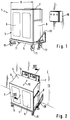
- FIG. 1 shows a heating device, generally designated 1, for inductive heating or warming up of dishes portioned into induction dishes, which is placed on trays 2 for this purpose (see FIG. 6), each of which contains a complete menu.
- the heating device 1 has a substantially cuboid, box-shaped housing 3 with an upper side 4, a bottom 5, a front wall 6, a rear wall 7, two side walls 8 and 9 and one in the middle between the side walls 8 and 9 arranged intermediate wall 10 (see. Fig. 6), wherein the housing 3 is formed in two parts.
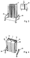
- the rear wall 7 forms a first housing part and the walls 4-6 and 8-10 form a second housing part, which on rollers 11 in the direction of the arrow 12 (see FIG. 2) relative to the one formed by the rear wall 7 a wall 13 arranged second housing part is movable, as will be described in detail below.
- two rows of ten horizontal heating trays 14 are arranged on the rear wall 7, the heating trays 14 of each row being aligned vertically to one another and their mutual vertical spacing a being constant. Adjacent heating floors 14, 14 are horizontally aligned with each other. Between them there is a gap with a width b.
- the rear wall 7 has a plurality of through holes and is screwed there to the wall 13 with fastening means such as screws.
- each of the heating floors 14 there is at least one coil which cannot be seen in the drawing, the coils being connected via electrical lines (not shown) to a control unit 16 in which the other components of an inductive heating device are arranged, by means of which the coils are used to generate a magnetic Alternating field must be charged with high-frequency alternating current if heating is to take place.
- the heating floors 14 arranged or formed in the manner of plate-shaped tongues, which are only attached with their rear edge 14 'to the rear wall 7 and project freely therefrom.
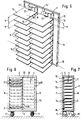
- separate support means 18 are provided for supporting the trays 2 on the inner sides of the side walls 8 and 9 and on the intermediate wall 10 (see FIG. 6), which can be designed, for example, as horizontal support strips or moldings, so that the trays 2 are each with their Edge can be supported on two mutually associated support means 18, 18 in a horizontal arrangement.
- the support means 18 are arranged so that the trays 2 are in the heating position (FIG. 1) immediately above a heating floor 14. Their relative position to the heating floors 14 can be seen in Fig. 6, which shows a side view of the open back of the second housing part 4-6, 8-10, where the heating floors 14 with dash-dotted lines in the retracted position of the two housing parts and thus are indicated in the heating position.
- the guide bracket 20 can be connected to the rear wall 7 or separated from it.
- d is (only) somewhat larger than the housing width B, so that the second housing part provided with the trays 2 can be centered in a simple manner during the relative movement to the first housing part and thus to the heating floors 14, without damaging it Collisions with the heating floors 14 or the trays 2 can come.
- FIG. 4 shows the training according to FIG. Fig. 3 shows a variant with alternative guide brackets 20 ', which extend over the entire height of the rear wall 7 and also protrude beyond the front edges of the heating floors 14.
- a guide bracket 20 ' is required inside the movable second housing part of corresponding receiving pockets or the like. between the side walls 8, 9 and further partition walls, on which the support means 18 are then arranged. This may require a special configuration of the second housing parts.
- Fig. 6 is an essentially complete assembly, and is then moved on its rollers 11 to the fixed in the area of an output station (for example. A hospital ward), from the rear wall 7 and the attached to the heating floors 14 "docking station" and there guided by guides 20 and 20 'to these. In the retracted heating position, the heating shelves 14 are centered on the trays 2, so that the heating can be switched on.
- an output station for example. A hospital ward
- the second housing part is moved away again from the “docking station” (FIG. 2), so that the trays with the heated food can be removed.
- a particular further advantage is that the like in larger medical wards. with a single "docking station” several second housing parts equipped with trays can be heated in succession.
- existing conventional tray trolleys can be used as second housing parts.
- the movable second housing parts are again loaded with trays and empty containers after taking the food, they can - if necessary after removing the dishes that are still to be completely emptied and possibly cleaned separately - with the trays entered or the like in a car wash. be introduced, as is increasingly desired.
Landscapes
- Engineering & Computer Science (AREA)
- Food Science & Technology (AREA)
- Physics & Mathematics (AREA)
- Electromagnetism (AREA)
- General Induction Heating (AREA)
- General Preparation And Processing Of Foods (AREA)
- Devices For Warming Or Keeping Food Or Tableware Hot (AREA)
Applications Claiming Priority (2)
| Application Number | Priority Date | Filing Date | Title |
|---|---|---|---|
| DE29601788U | 1996-02-05 | ||
| DE29601788U DE29601788U1 (de) | 1996-02-05 | 1996-02-05 | Einrichtung zum induktiven Erwärmen von Speisen |
Publications (1)
| Publication Number | Publication Date |
|---|---|
| EP0787455A1 true EP0787455A1 (fr) | 1997-08-06 |
Family
ID=8018896
Family Applications (1)
| Application Number | Title | Priority Date | Filing Date |
|---|---|---|---|
| EP96109848A Withdrawn EP0787455A1 (fr) | 1996-02-05 | 1996-06-19 | Dispositif à chauffer des plats par induction |
Country Status (2)
| Country | Link |
|---|---|
| EP (1) | EP0787455A1 (fr) |
| DE (1) | DE29601788U1 (fr) |
Cited By (3)
| Publication number | Priority date | Publication date | Assignee | Title |
|---|---|---|---|---|
| DE29817272U1 (de) * | 1998-09-25 | 2000-02-03 | Lic Tec Ag, Cham | Heizregal |
| WO2005084503A1 (fr) * | 2004-03-03 | 2005-09-15 | Aerofoodtec | Dispositif de traitement de produits alimentaires |
| EP2472185A4 (fr) * | 2009-08-27 | 2014-12-10 | Mitsubishi Electric Corp | Dispositif de chauffage |
Families Citing this family (3)
| Publication number | Priority date | Publication date | Assignee | Title |
|---|---|---|---|---|
| DE19627522A1 (de) * | 1996-07-09 | 1998-01-15 | Etol Vertriebs Gmbh | Speisetablett |
| DE19818831C2 (de) * | 1998-04-27 | 2003-11-13 | Hubert Eric Walter | Verfahren, Vorrichtung und Behältnis zur Erwärmung vorgefertigter Speisen |
| FR2803653B1 (fr) * | 2000-01-10 | 2002-04-19 | Electro Calorique | Dispositif pour le maintien au froid et la mise en temperature de plateaux-repas et installation mettant en oeuvre un tel dispositif |
Citations (5)
| Publication number | Priority date | Publication date | Assignee | Title |
|---|---|---|---|---|
| DE1431680A1 (de) * | 1965-06-03 | 1968-11-28 | Homann Maytag Gmbh | Verfahren zur Versorgung von Verbrauchern,insbesondere Krankenhausinsassen u.dgl.,mit warmen Speisen |
| FR2345123A1 (fr) * | 1976-02-04 | 1977-10-21 | Orega Electro Mecanique | Dispositif multi-tablettes de chauffage par induction a enceinte refrigeree, pour stockage sur plateaux mobiles de substances, notamment alimentaires |
| FR2383637A1 (fr) * | 1975-03-20 | 1978-10-13 | Souder James | Procede et appareil de chauffage des aliments |
| US4757184A (en) * | 1986-12-24 | 1988-07-12 | Swanson David L | Rack loaded, radiant heated, cantilevered deck oven and method |
| EP0666047A1 (fr) * | 1994-02-02 | 1995-08-09 | Florinius-Investimentos E Servicos Internacionais, Lda | Procédé de remise à température d'un repas, récipient et appareil pour sa mise en oeuvre |
-
1996
- 1996-02-05 DE DE29601788U patent/DE29601788U1/de not_active Expired - Lifetime
- 1996-06-19 EP EP96109848A patent/EP0787455A1/fr not_active Withdrawn
Patent Citations (5)
| Publication number | Priority date | Publication date | Assignee | Title |
|---|---|---|---|---|
| DE1431680A1 (de) * | 1965-06-03 | 1968-11-28 | Homann Maytag Gmbh | Verfahren zur Versorgung von Verbrauchern,insbesondere Krankenhausinsassen u.dgl.,mit warmen Speisen |
| FR2383637A1 (fr) * | 1975-03-20 | 1978-10-13 | Souder James | Procede et appareil de chauffage des aliments |
| FR2345123A1 (fr) * | 1976-02-04 | 1977-10-21 | Orega Electro Mecanique | Dispositif multi-tablettes de chauffage par induction a enceinte refrigeree, pour stockage sur plateaux mobiles de substances, notamment alimentaires |
| US4757184A (en) * | 1986-12-24 | 1988-07-12 | Swanson David L | Rack loaded, radiant heated, cantilevered deck oven and method |
| EP0666047A1 (fr) * | 1994-02-02 | 1995-08-09 | Florinius-Investimentos E Servicos Internacionais, Lda | Procédé de remise à température d'un repas, récipient et appareil pour sa mise en oeuvre |
Cited By (3)
| Publication number | Priority date | Publication date | Assignee | Title |
|---|---|---|---|---|
| DE29817272U1 (de) * | 1998-09-25 | 2000-02-03 | Lic Tec Ag, Cham | Heizregal |
| WO2005084503A1 (fr) * | 2004-03-03 | 2005-09-15 | Aerofoodtec | Dispositif de traitement de produits alimentaires |
| EP2472185A4 (fr) * | 2009-08-27 | 2014-12-10 | Mitsubishi Electric Corp | Dispositif de chauffage |
Also Published As
| Publication number | Publication date |
|---|---|
| DE29601788U1 (de) | 1996-05-02 |
Similar Documents
| Publication | Publication Date | Title |
|---|---|---|
| DE2801063C2 (fr) | ||
| DE69801788T2 (de) | Verfahren und Vorrichtung zum Verteilen von Gemeinschaftsverpflegung | |
| DE602004003692T2 (de) | Vorrichtung zum Laden und Entladen von Behältern | |
| EP0407742B1 (fr) | Disposition d'un four muni de support téléscopique | |
| EP1712859B1 (fr) | Procédé pour faire fonctionner des installations de lyophilisation avec une chambre et avec dispositifs de chargement et de déchargement, et installations appropriées de ce type | |
| DE69701080T2 (de) | Speisetablett zum Erwärmen von Nahrungsmitteln | |
| DE29601788U1 (de) | Einrichtung zum induktiven Erwärmen von Speisen | |
| EP0034295A2 (fr) | Installation de cuisine encastrée | |
| DE2459479A1 (de) | Baeckereibetriebsverfahren | |
| DE20005770U1 (de) | Unterschrank für medizinische Geräte | |
| DE69502737T2 (de) | Verfahren zum Erwärmen einer Mahlzeit, Behälter und Gerät zur Durchführung des Verfahrens | |
| EP1720436A1 (fr) | Dispositif de traitement de produits alimentaires | |
| EP3768117A1 (fr) | Élément structural de meuble | |
| CH684876A5 (de) | Wagen zum Transportieren von Speisen. | |
| EP0776145B1 (fr) | Dispositif à induction pour réchauffer des aliments | |
| WO2017032592A1 (fr) | Dispositif de préparation de commandes et procédé pour faire fonctionner un dispositif de préparation de commandes | |
| DE3004410C2 (de) | Einbauback- und-bratofen für Einbaukücheneinrichtungen | |
| DE2636274C3 (de) | Vorrichtung zum Verteilen von Mahlzeiten | |
| EP2364621A2 (fr) | Station de travail pour une installation destinée à la mise en portion de repas sur des plateaux repas | |
| DE888878C (de) | Gestellaufbau | |
| DE8222651U1 (de) | Hochfrequenzheizgeraet | |
| EP1101433A1 (fr) | Dispositif pour rechauffer de la nourriture | |
| DE2624517C3 (de) | Schrank mit höhenverstellbaren Fachböden | |
| DE202009004461U1 (de) | Kombination aus mindestens einem Speisenbehälter und einem Trägerelement | |
| DE102018008653B4 (de) | Auszugsvorrichtung für Möbel und Möbel mit dieser Auszugsvorrichtung |
Legal Events
| Date | Code | Title | Description |
|---|---|---|---|
| PUAI | Public reference made under article 153(3) epc to a published international application that has entered the european phase |
Free format text: ORIGINAL CODE: 0009012 |
|
| AK | Designated contracting states |
Kind code of ref document: A1 Designated state(s): AT CH DE LI |
|
| STAA | Information on the status of an ep patent application or granted ep patent |
Free format text: STATUS: THE APPLICATION IS DEEMED TO BE WITHDRAWN |
|
| 18D | Application deemed to be withdrawn |
Effective date: 19980207 |