EP0787509A2 - Stützvorrichtung für ein Basketballzielbrett, Spielfeld und Sporthalle mit einer solchen Stützvorrichtung versehen - Google Patents
Stützvorrichtung für ein Basketballzielbrett, Spielfeld und Sporthalle mit einer solchen Stützvorrichtung versehen Download PDFInfo
- Publication number
- EP0787509A2 EP0787509A2 EP97420019A EP97420019A EP0787509A2 EP 0787509 A2 EP0787509 A2 EP 0787509A2 EP 97420019 A EP97420019 A EP 97420019A EP 97420019 A EP97420019 A EP 97420019A EP 0787509 A2 EP0787509 A2 EP 0787509A2
- Authority
- EP
- European Patent Office
- Prior art keywords
- panel
- basketball
- base
- arm
- backboard
- Prior art date
- Legal status (The legal status is an assumption and is not a legal conclusion. Google has not performed a legal analysis and makes no representation as to the accuracy of the status listed.)
- Withdrawn
Links
Images


Classifications
-
- A—HUMAN NECESSITIES
- A63—SPORTS; GAMES; AMUSEMENTS
- A63B—APPARATUS FOR PHYSICAL TRAINING, GYMNASTICS, SWIMMING, CLIMBING, OR FENCING; BALL GAMES; TRAINING EQUIPMENT
- A63B63/00—Targets or goals for ball games
- A63B63/08—Targets or goals for ball games with substantially horizontal opening for ball, e.g. for basketball
- A63B63/083—Targets or goals for ball games with substantially horizontal opening for ball, e.g. for basketball for basketball
-
- A—HUMAN NECESSITIES
- A63—SPORTS; GAMES; AMUSEMENTS
- A63B—APPARATUS FOR PHYSICAL TRAINING, GYMNASTICS, SWIMMING, CLIMBING, OR FENCING; BALL GAMES; TRAINING EQUIPMENT
- A63B2208/00—Characteristics or parameters related to the user or player
- A63B2208/12—Characteristics or parameters related to the user or player specially adapted for children
-
- A—HUMAN NECESSITIES
- A63—SPORTS; GAMES; AMUSEMENTS
- A63B—APPARATUS FOR PHYSICAL TRAINING, GYMNASTICS, SWIMMING, CLIMBING, OR FENCING; BALL GAMES; TRAINING EQUIPMENT
- A63B2225/00—Miscellaneous features of sport apparatus, devices or equipment
- A63B2225/09—Adjustable dimensions
- A63B2225/093—Height
Definitions
- the invention relates to a device for supporting a basketball hoop and to a field or a sports hall comprising such a device.
- a basketball board In accordance with the rules decreed by the various national and international federations, a basketball board must be supported in a determined position relative to the ground on which the players play. This position is in particular determined by the height of the basket circle which must be approximately 3.05 m and by the vertical alignment of the front face of the panel with respect to the bottom line of the terrain which must be approximately 1.20 m.
- mini-basketball new rules of the game
- a second panel can be hung on the existing panel for adult players, this second panel being shifted forward and downward so as to be accessible to young players.
- the attachment of the second panel is not perfect and it can be more or less dangerous because it may fall off if it is subjected to strong shocks or to the effect of the wind.
- this device requires the operation in height of a second panel whose weight can reach 10 to 15 kg, which implies the intervention of one or more adults for its installation.
- the devices of the prior art use a different panel for the practice of mini-basketball and for the practice of basketball itself, which implies a double investment for the municipalities or associations in charge of this sport.
- the invention more particularly intends to remedy by proposing a support device for a basketball hoop allowing an adequate positioning thereof in the playing position for adults.
- the invention relates to a device for supporting a panel of a basketball comprising a parallelogram structure, arranged between the panel and a base, movable between two positions corresponding to two playing positions of the panel, characterized in that the parallelogram structure includes a plurality of arms formed of two sections oriented obliquely to each other.
- the arms forming the parallelogram structure do not oppose the approximation of the basketball hoop relative to the support base and this, whatever their length.
- the section connected to the panel of a lower arm of the parallelogram structure and the section connected to the base of an upper arm are parallel when the panel is in its high position.
- the shape of the arms of the parallelogram structure is particularly suitable for compact positioning of this structure when the panel is in the high position.
- the device comprises two slings defining the maximum distance of elements respectively secured to the panel and the base. These slings serve to limit the downward travel of the panel and constitute load-bearing elements and safety elements for the device.
- the device further comprises an operating arm kinematically connected to the panel and to the base, this operating arm being able to move the panel relative to the base.
- An operating lever can be removably attached to the operating arm and allows the panel to be moved between these two positions by a user located on the ground.
- means for returning the parallelogram structure to one of the two positions, for example in its high position also make it possible to guarantee good mechanical stability of the device.
- Means for locking the parallelogram structure in one of its positions may be provided, this locking means possibly being a stiffener formed by two sections articulated with respect to each other.
- the locking means can be controlled by the operating lever.
- the base carries a cable strand winding mechanism, the end of which is secured to the panel.
- This aspect of the invention allows efficient and precise maneuvering of the panel by means of a crank.
- the device comprises energy storage abutment means arranged between the panel and the base, these abutment means being compressed when the panel is in its high position.
- These stop means serve in particular to initiate the downward movement of the panel from its high position.
- the invention finally relates to a sports field comprising a device according to the invention.
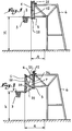
- the panel 1 shown in Figure 1 supports a metal circle 2 to which is hung a basket 3, this assembly used for the practice of basketball.
- the panel 1 is held in a position determined by a structure 4, for example metallic, so that the basket is located at a height H of 3.05 m and that the plumb A of the front face of the panel 1 relative to the baseline of the playing field is 1.20 m.
- a structure 4 for example metallic
- the panel has been moved so that the circle 2 is at a height h of 2.60 m from the ground and that the front face of the panel 1 has a plumb a of 1.80 m with respect to the end line of the playing field.
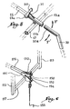
- the displacement of the panel 1 from the position of FIG. 1 to the position of FIG. 2 is possible thanks to a parallelogram structure which appears more clearly in FIGS. 3 and 4.
- a base 5 belonging to the metal structure 4 is connected to the panels 1 by four arms 6, 7, 8 and 9 articulated in U-shaped angles 10, 11, 12 and 13.
- the angles 12 and 13 are fixed by any suitable means on the base 5, they are for example bolted or welded thereto.
- the panel 1 is fixed by any suitable means, for example bolted to the angles 10 and 11.
- the parallelogram structure formed by the elements 6 to 13 is movable between two positions corresponding to the two playing positions shown in FIGS. 1 and 2. In these two playing positions defined for players of different sizes and ages, a single panel 1 is used.
- the arm 6 consists of two sections 6 a and 6 b oriented obliquely with respect to each other while the arm 7 also consists of two sections 7 a and 7 b oriented obliquely one in relation to the other.
- the angles of orientation of sections 6 a , 6 b , 7 a , 7 b are such that sections 7 a and 6 b are parallel when the panel is in its high position as shown in FIG. 3, so that the superimposition of the arms 6 and 7 does not disturb the approximation of the panel 1 of the base 5.
- the pivoting of the arm 7 relative to its axis articulation 7 c is not hampered by the lower part of the arm 6.
- the device also comprises an operating arm 15 articulated on the panel 1, for example by means of a U-shaped angle iron 16 and mounted to rotate freely on one of the two spacers 17 and 18 connecting the angles 12 and 13. Given the fixing of the angles 12 and 13 to the base 5, the movement arm 15 is kinematically connected to the base 5.
- An operating lever 20 can be adapted to the end 15a of the movement arm 15 distant from the panel 1 so as to allow a user to exert a torque F or F 'intended to pivot the movement arm 15 around its hinge pin on the spacer 17.
- the lever 20 penetrates inside the end 15 a of the operating arm 15. More specifically, in the position of FIG. 4, if a user exercises on the lever 20 a force such that a torque F ′ is exerted on the movement arm 15, the panel 1 is raised to its position in FIG. 3 and the movement arm 15 is placed in a substantially vertical position. Conversely, if a torque F is exerted on the movement arm 15 in the position of FIG. 3, the movement arm pushes the panel 1 towards its position in FIG. 4.
- the operating lever 20 is fixed so removable on the operating arm 15 so as to allow control of the movement between the two playing positions of the panel 1 when necessary, but not to interfere with the game when players use the field.
- two return springs 21 and 22 may be arranged between the structure 4 and the panel 1.
- the springs 21 and 22 are bandaged, so that they exert on the panel 1 an effort tending to bring their respective ends together, that is to say the panel 1 and the structure 4.
- This effort assists the movement of the parallelogram structure when the user exerts on the lever 20 an effort in the direction of the arrow F 'to reassemble the panel in the position of FIG. 3.
- the springs 21 and 22 therefore constitute an elastic return means of the parallelogram structure in the position of FIG. 3.
- the springs are precompressed springs with contiguous turns, so that in their rest state corresponding to the position of FIG. 3, they do not allow relative movement of their ends only when subjected to a force exceeding a nominal threshold value.
- the displacement obtained by a force on one of the ends of the springs 21 and 22 is effective only when the force in question is greater than a threshold value.
- This contributes to maintaining the parallelogram structure in its position in FIG. 3. Indeed, during a basketball match, it happens that a player strikes or temporarily suspends from basket 2 of panel 1, this which results in a downward force exerted on the panel. It is therefore essential that the panel 1 does not move into the position of FIG. 4 because of this effort. Given the fact that they are pre-compressed and with contiguous turns, the springs 21 and 22 prevent movement of the panel 1 when the force exerted on the panel 1 is less than a certain threshold value.
- the maintenance of the panel 1 in its position in FIG. 4 is achieved by means of the movement arm 15.
- the base 5 is provided with a notch 5 a forming stop for movement of the end 15 a of the movement arm 15, so that the rotational movement of the movement arm 15 is limited upwards by the base 5, which limits the downward movement of the panel 1 .
- two safety slings 30 and 31 are respectively stretched between the U-shaped angles 10, 12 and 11, 13 so that their length defines the maximum distance between the points of the angles to which they are connected. This also limits the movement of the panel 1 downwards and constitutes a means of blocking the parallelogram structure in the position of FIG. 4.
- a stiffener 32 formed of two sections 32 a and 32 b articulated with respect to each other about a common axis 32 c , is fixed both on the angle 10 and on the angle 12, it - even mounted on the base 5, so that the stiffener 32 is integral with both the panel 1 and the base 5. It can be provided that the stiffener 32 is articulated on the angle 12 by means of the axis 7 c of articulation of the arm 7.
- the sections 32 a and 32 b of the stiffener 32 have a geometry such that, when the panel 1 is in its position in FIG. 4, two of their respective faces 32 d and 32 e are in abutment one against the other so as to form a stop limiting the movement of the panel 1 downwards.
- a sling 34 is stretched between one, for example 32b, of the sections of the stiffener 32 and the angle iron to which this section is not connected, in the example the angle 10.
- the angle 10 is slightly lifted upward, which causes the sling 34 exerts a force on the section 32b upward. This effort unlocks the stiffener 32, which allows the movement of the panel 1 upwards.
- a single stiffener 32 can block the panel 1 in the low position. However, when the panel 1 is installed outdoors, that is to say exposed to the wind, provision may be made for a second stiffener 35 to be installed.
- the number of stiffeners is not limited to two and can be increased if necessary.
- the movement arm 15 further carries a stop 50 intended to penetrate into a notch 5 b of the base 5 visible at the Figure 4.
- This retainer 50 is used to immobilize the panel 1 in its position of Figure 3 and thus represents an alternative to the pre-compressed springs 21 and 22 previously described.
- the geometry of the stopper 50 allows it to be automatically placed in the corresponding notch in the base 5 when the panel 1 moves to its position in FIG. 3.
- a slit 15 b is formed on a side faces of the movement arm 15 and extends up to the point of articulation 15 c of the retainer 50 on the arm 15.
- the end of the operating lever 20 intended to penetrate inside the arm movement 15 is, for its part, provided with a longitudinal pin 20 a capable of penetrating into the slot 15 a and of exerting on the retainer 50 an axial force tending to lift it against the return force of the spring 51 when in the position of Figure 3, so that the retainer 50 is unlocked relative to the notch of the base 5 into which it enters.
- the means for locking in position can be constituted by the retainer 50 controlled by the operating lever 20.
- FIG. 6 is a detail view similar to FIG. 5 for a second embodiment of the invention in which the elements similar to those of FIGS. 1 to 5 bear identical references increased by 100.
- the operating arm 115 is moved in rotation about its axis of articulation on the spacer 117 by means of a nut 150 trapped in two cheeks 151 and 152 secured to arm 115.
- a threaded rod 153 mounted substantially vertical in a base 154 is controlled by a crank 155. By rotation of the threaded rod 153, the nut 150 is moved along the axis of symmetry of the rod 153, which has the effect of driving the operating arm 115.
- the diameter of the threaded rod is chosen in the range of 20 to 25 mm and its pitch between 4 and 6 mm, so that the assembly of the rod 153 and the nut 150 is self-locking, that is to say constitutes an irreversible screw-nut system.
- the assembly formed by the rod 153 and the nut 150 therefore constitutes a means for locking the panel 1 in position.
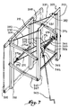
- a panel 201 is movable between two play positions thanks to a structure comprising a base 205 and four arms 206, 207, 208 and 209 articulated on rectangular crosspieces 210, 211, 212 and 213.
- the arms 206 to 209 are each formed of two sections oriented obliquely to each other.
- This embodiment of the invention differs from the previous one essentially in that it comprises a mechanism 260 for winding cable strands, essentially consisting of a winding shaft 261 engaged on a bevel gear 262 which can be controlled by a crank 263 which can be temporarily hooked to an operating eyelet 264 of the bevel gear 262.
- Two strands 271 and 272 of lifting cable are capable of being wound around the shaft 261 according to its angular position.
- the ends 271 a , 272 has cable strands 271 and 272 are fixed by any suitable means to a rod 273 secured to the crosspieces 210 and 211. The end of the strands 271 and 272 is thus secured to the panel 201.
- the strands 271 and 272 belong to a single cable 270, the central part 274 of which is stretched between two stops 275 and 276 fixed on the shaft 261.
- the traction forces of the strands 271 and 272 are thus automatically balanced.
- Two slings 230 and 231 are arranged between the respective upper parts of the cross members 210 and 212 on the one hand, and of the cross members 211 and 213 on the other hand. These slings are tensioned when the panel 201 is in its low position. They thus define the maximum distance from the panel 201 and from the base 205.
- the angular gear 262 is actuated using the crank 263 so as to wind the strands 271 and 272 of cable 270 on the shaft 261.
- the rod 273 is thus brought closer to the shaft 261 which, taking into account the articulation produced by the arms 206 to 209, induces the ascent of the panel 201.
- Two spring stops 281 and 282 are provided at the upper part of the base 205, on the side of the panel 201. They are thus arranged between the panel 201 and the base 205. When the panel 201 arrives in its high position, a angle 283 disposed in its upper part compresses the stops 281 and 282, so that these store a certain energy.
- the bevel gear 262 is chosen irreversible so that when the panel is in its high position, it suffices to unhook the crank 263 from the eyelet 264 so that the panel 201 remains in its high position.
- the angular gear 262 is driven in the opposite direction to that used for raising the panel.
- the elastic stops initiate the downward movement, so that the panel 201 is cantilevered with respect to at the base 205 and that it continues its downward movement under its own weight to its low position.
- elastic stops equivalent to the stops 281 and 282 can be installed in the vicinity of the device 260, so that they exert a thrust in the central part of the panel 201.
- the invention has been presented with a mobile panel between two playing positions, but it is also applicable to a mobile panel between three or more than three playing positions, corresponding for example to three or more of three categories of players, provided that at least one locking means such as those described with reference to the embodiment shown is used in each position.
- the invention has been presented with a fixed base 5, as carried by the metallic and rigid structure 4.
- the invention is also applicable to the case where the base is mobile, for example suspended from the ceiling of a multi room -sports by slings maneuvered using a mechanical or electric winch or by any other equivalent means.
Landscapes
- Health & Medical Sciences (AREA)
- General Health & Medical Sciences (AREA)
- Physical Education & Sports Medicine (AREA)
- Pivots And Pivotal Connections (AREA)
- Toys (AREA)
- Road Signs Or Road Markings (AREA)
Applications Claiming Priority (2)
| Application Number | Priority Date | Filing Date | Title |
|---|---|---|---|
| FR9601322 | 1996-01-30 | ||
| FR9601322A FR2744027B1 (fr) | 1996-01-30 | 1996-01-30 | Dispositif de supportage d'un panneau de basket-ball, terrain et salle de sport comprenant un tel dispositif |
Publications (2)
| Publication Number | Publication Date |
|---|---|
| EP0787509A2 true EP0787509A2 (de) | 1997-08-06 |
| EP0787509A3 EP0787509A3 (de) | 1998-07-22 |
Family
ID=9488808
Family Applications (1)
| Application Number | Title | Priority Date | Filing Date |
|---|---|---|---|
| EP97420019A Withdrawn EP0787509A3 (de) | 1996-01-30 | 1997-01-30 | Stützvorrichtung für ein Basketballzielbrett, Spielfeld und Sporthalle mit einer solchen Stützvorrichtung versehen |
Country Status (2)
| Country | Link |
|---|---|
| EP (1) | EP0787509A3 (de) |
| FR (1) | FR2744027B1 (de) |
Family Cites Families (7)
| Publication number | Priority date | Publication date | Assignee | Title |
|---|---|---|---|---|
| US2227310A (en) * | 1939-05-23 | 1940-12-31 | Everwear Mfg Company | Basket-ball backstop apparatus |
| US4781375A (en) * | 1986-10-21 | 1988-11-01 | Lifetime Products, Inc. | Method and apparatus for adjusting a basketball goal |
| US4798381A (en) * | 1987-07-06 | 1989-01-17 | Harvard Sports, Inc. | Basketball goal height adjustment apparatus |
| US5133547A (en) * | 1991-01-22 | 1992-07-28 | Jayfro Corporation | Self-adjusting basketball goal |
| US5478068A (en) * | 1992-07-30 | 1995-12-26 | Porter Athletic Equipment Company | Wheeled portable basketball goal assembly |
| US5388821A (en) * | 1993-08-10 | 1995-02-14 | Blackburn; Michael J. | Force limiting adjustable basketball goal |
| AUPM382094A0 (en) * | 1994-02-09 | 1994-03-03 | Gorman, Jeremy Peter | Adjustable basketball frame |
-
1996
- 1996-01-30 FR FR9601322A patent/FR2744027B1/fr not_active Expired - Fee Related
-
1997
- 1997-01-30 EP EP97420019A patent/EP0787509A3/de not_active Withdrawn
Also Published As
| Publication number | Publication date |
|---|---|
| FR2744027B1 (fr) | 1998-05-07 |
| EP0787509A3 (de) | 1998-07-22 |
| FR2744027A1 (fr) | 1997-08-01 |
Similar Documents
| Publication | Publication Date | Title |
|---|---|---|
| FR2549029A1 (fr) | Elevateur comportant au moins un mat telescopique | |
| EP0379448A1 (de) | Kran mit anhebbarem Ausleger und mit einer Ausleger-Rückstossvorrichtung | |
| FR2659311A1 (fr) | Dispositif motorise de prehension de charge a commande a distance. | |
| FR2624494A3 (fr) | Appareil de levage a potence pour trou d'homme | |
| EP0749548B1 (de) | Bewegliche vorrichtung vom typ sonnenschirmständer mit versenkbaren und nicht sichtbaren raedern | |
| EP1148022A1 (de) | Rahmen für Hubgondel und Scherenhubgondel mit einem solchen Rahmen | |
| EP1668186A1 (de) | Brücke, insbesondere zum überqueren eines schifffahrtsstrassendurchgangs | |
| EP0787509A2 (de) | Stützvorrichtung für ein Basketballzielbrett, Spielfeld und Sporthalle mit einer solchen Stützvorrichtung versehen | |
| EP0803466B1 (de) | Verfahren und Vorrichtung zum sicheren Besteigen einer Kabine, insbesondere auf einem Turmkran | |
| FR2540168A1 (fr) | Appareils montes sur colonne | |
| FR2689073A1 (fr) | Appareillage de manutention de charges allongées sur le toit d'un véhicule. | |
| FR2648101A1 (fr) | Dispositif de blocage des roues d'un vehicule, en particulier d'un vehicule non autopropulse | |
| EP4474334A1 (de) | Fahrzeughebevorrichtung | |
| EP2572695B1 (de) | Hebestuhl | |
| EP0863092B1 (de) | Kippvorrichtung für ein Piano | |
| FR2571471A1 (fr) | Trepied telescopique deplacable pour installations d'eclairage en particulier pour tournage de films ou analogues | |
| EP0330556B1 (de) | Drehscheibe zum Ausstellen eines Kraftfahrzeuges | |
| CA1312055C (fr) | Escalier repliable pour vehicules | |
| FR2628466A1 (fr) | Etai de longueur reglable | |
| EP0052051A1 (de) | Simulator für ein Segelbrett | |
| FR2584300A1 (fr) | But de basket-ball relevable avec panneau reglable en hauteur | |
| FR2659567A1 (fr) | Manege a nacelle tubulaire. | |
| FR2626865A1 (fr) | Nacelle pour fleche telescopique d'engin de levage | |
| FR2609745A1 (fr) | Dispositif de manutention pour branches destinees au coffrage de voiles de beton | |
| FR2766729A1 (fr) | Dispositif de supportage d'un panneau de basket-ball entre deux positions de jeu, terrain ou salle de sport comprenant un tel dispositif |
Legal Events
| Date | Code | Title | Description |
|---|---|---|---|
| PUAI | Public reference made under article 153(3) epc to a published international application that has entered the european phase |
Free format text: ORIGINAL CODE: 0009012 |
|
| AK | Designated contracting states |
Kind code of ref document: A2 Designated state(s): BE CH DE ES FR IT LI |
|
| PUAL | Search report despatched |
Free format text: ORIGINAL CODE: 0009013 |
|
| AK | Designated contracting states |
Kind code of ref document: A3 Designated state(s): BE CH DE ES FR IT LI |
|
| 17P | Request for examination filed |
Effective date: 19981031 |
|
| STAA | Information on the status of an ep patent application or granted ep patent |
Free format text: STATUS: THE APPLICATION HAS BEEN WITHDRAWN |
|
| 18W | Application withdrawn |
Withdrawal date: 20010115 |