EP0787560B2 - Dispositif d'usinage des barres, des profilés et similaire - Google Patents
Dispositif d'usinage des barres, des profilés et similaire Download PDFInfo
- Publication number
- EP0787560B2 EP0787560B2 EP97100989A EP97100989A EP0787560B2 EP 0787560 B2 EP0787560 B2 EP 0787560B2 EP 97100989 A EP97100989 A EP 97100989A EP 97100989 A EP97100989 A EP 97100989A EP 0787560 B2 EP0787560 B2 EP 0787560B2
- Authority
- EP
- European Patent Office
- Prior art keywords
- profile
- clamping
- shaft
- machining
- processing unit
- Prior art date
- Legal status (The legal status is an assumption and is not a legal conclusion. Google has not performed a legal analysis and makes no representation as to the accuracy of the status listed.)
- Expired - Lifetime
Links
Images

Classifications
-
- B—PERFORMING OPERATIONS; TRANSPORTING
- B27—WORKING OR PRESERVING WOOD OR SIMILAR MATERIAL; NAILING OR STAPLING MACHINES IN GENERAL
- B27F—DOVETAILED WORK; TENONS; SLOTTING MACHINES FOR WOOD OR SIMILAR MATERIAL; NAILING OR STAPLING MACHINES
- B27F5/00—Slotted or mortised work
- B27F5/02—Slotting or mortising machines tools therefor
- B27F5/12—Slotting or mortising machines tools therefor for making holes designed for taking up fittings, e.g. in frames of doors, windows, furniture
-
- B—PERFORMING OPERATIONS; TRANSPORTING
- B23—MACHINE TOOLS; METAL-WORKING NOT OTHERWISE PROVIDED FOR
- B23Q—DETAILS, COMPONENTS, OR ACCESSORIES FOR MACHINE TOOLS, e.g. ARRANGEMENTS FOR COPYING OR CONTROLLING; MACHINE TOOLS IN GENERAL CHARACTERISED BY THE CONSTRUCTION OF PARTICULAR DETAILS OR COMPONENTS; COMBINATIONS OR ASSOCIATIONS OF METAL-WORKING MACHINES, NOT DIRECTED TO A PARTICULAR RESULT
- B23Q1/00—Members which are comprised in the general build-up of a form of machine, particularly relatively large fixed members
- B23Q1/25—Movable or adjustable work or tool supports
- B23Q1/44—Movable or adjustable work or tool supports using particular mechanisms
- B23Q1/50—Movable or adjustable work or tool supports using particular mechanisms with rotating pairs only, the rotating pairs being the first two elements of the mechanism
- B23Q1/52—Movable or adjustable work or tool supports using particular mechanisms with rotating pairs only, the rotating pairs being the first two elements of the mechanism a single rotating pair
- B23Q1/527—Movable or adjustable work or tool supports using particular mechanisms with rotating pairs only, the rotating pairs being the first two elements of the mechanism a single rotating pair with a ring or tube in which a workpiece is fixed coaxially to the degree of freedom
-
- Y—GENERAL TAGGING OF NEW TECHNOLOGICAL DEVELOPMENTS; GENERAL TAGGING OF CROSS-SECTIONAL TECHNOLOGIES SPANNING OVER SEVERAL SECTIONS OF THE IPC; TECHNICAL SUBJECTS COVERED BY FORMER USPC CROSS-REFERENCE ART COLLECTIONS [XRACs] AND DIGESTS
- Y10—TECHNICAL SUBJECTS COVERED BY FORMER USPC
- Y10T—TECHNICAL SUBJECTS COVERED BY FORMER US CLASSIFICATION
- Y10T408/00—Cutting by use of rotating axially moving tool
- Y10T408/55—Cutting by use of rotating axially moving tool with work-engaging structure other than Tool or tool-support
- Y10T408/561—Having tool-opposing, work-engaging surface
- Y10T408/5614—Angularly adjustable surface
-
- Y—GENERAL TAGGING OF NEW TECHNOLOGICAL DEVELOPMENTS; GENERAL TAGGING OF CROSS-SECTIONAL TECHNOLOGIES SPANNING OVER SEVERAL SECTIONS OF THE IPC; TECHNICAL SUBJECTS COVERED BY FORMER USPC CROSS-REFERENCE ART COLLECTIONS [XRACs] AND DIGESTS
- Y10—TECHNICAL SUBJECTS COVERED BY FORMER USPC
- Y10T—TECHNICAL SUBJECTS COVERED BY FORMER US CLASSIFICATION
- Y10T408/00—Cutting by use of rotating axially moving tool
- Y10T408/55—Cutting by use of rotating axially moving tool with work-engaging structure other than Tool or tool-support
- Y10T408/563—Work-gripping clamp
- Y10T408/5635—Oppositely moving lateral clamps
-
- Y—GENERAL TAGGING OF NEW TECHNOLOGICAL DEVELOPMENTS; GENERAL TAGGING OF CROSS-SECTIONAL TECHNOLOGIES SPANNING OVER SEVERAL SECTIONS OF THE IPC; TECHNICAL SUBJECTS COVERED BY FORMER USPC CROSS-REFERENCE ART COLLECTIONS [XRACs] AND DIGESTS
- Y10—TECHNICAL SUBJECTS COVERED BY FORMER USPC
- Y10T—TECHNICAL SUBJECTS COVERED BY FORMER US CLASSIFICATION
- Y10T409/00—Gear cutting, milling, or planing
- Y10T409/30—Milling
- Y10T409/306664—Milling including means to infeed rotary cutter toward work
- Y10T409/307448—Milling including means to infeed rotary cutter toward work with work holder
- Y10T409/307504—Indexable
-
- Y—GENERAL TAGGING OF NEW TECHNOLOGICAL DEVELOPMENTS; GENERAL TAGGING OF CROSS-SECTIONAL TECHNOLOGIES SPANNING OVER SEVERAL SECTIONS OF THE IPC; TECHNICAL SUBJECTS COVERED BY FORMER USPC CROSS-REFERENCE ART COLLECTIONS [XRACs] AND DIGESTS
- Y10—TECHNICAL SUBJECTS COVERED BY FORMER USPC
- Y10T—TECHNICAL SUBJECTS COVERED BY FORMER US CLASSIFICATION
- Y10T409/00—Gear cutting, milling, or planing
- Y10T409/30—Milling
- Y10T409/30868—Work support
- Y10T409/308792—Indexable
Definitions
- the invention relates to a device according to the preamble of claim 1.
- a device is known from US-3,918,145-A.
- the clamping device is mounted pivotably about a horizontal pivot axis, wherein the clamping device is mounted in the machine frame about a parallel to the longitudinal axis of the hollow profile pivot axis by at least 180 ° ,
- the holder of the hollow profile is carried out by compressed air actuated clamping cylinder, which clamp the hollow profile with respect to a contact surface.
- a circular arc guide By means of a circular arc guide the hollow profile is pivoted about a pivot axis parallel to the longitudinal axis of the hollow profile.
- the drive of the hollow profile via arranged on the machine frame bearing rollers.
- the rotary actuator is actuated by two pressure medium swivel cylinder, the drive for pivoting the hollow profile is designed very expensive and the storage of the jig.
- Machines of the type mentioned are known. On a machine table, the profile to be machined is clamped. In the profiles, for example, plastic, wood or metal profiles can be used. On the profiles, which are processed or processed, for example, as Stangenpreßprofile or extruded profiles, preparatory work is to be carried out. For example, windows are produced from the profiles, wherein recesses for the fitting of valves, drives or the like are to be provided in the profiles.
- the tool carrier In the processing of this bar material, it is disadvantageous that they are to be processed on a plurality of sides.
- the tool carrier is designed to be pivotable and thereby a multi-side machining of the profile is possible.
- Such a configuration is correspondingly expensive, since the tool carrier, in particular the tool spindles, must have a high precision and the corresponding Verschwenkmechaniscmus must also have a high quality.
- the invention proceeds from the device, as described above, and proposes a device according to claim 1.
- Such an embodiment of the invention ensures that the profile can be processed in a simple manner on several sides. If, for example, a side is used as the visible side in the case of a four-sided profile, pivotability of the device through 180 °, for example, is sufficient. Of course it's possible; to edit any other profile shape by then the corresponding pivoting range of the device is selected.
- the two shafts are connected by a worktable.
- the production of long waves is difficult in high quality.
- a plurality of bearings are provided in order to derive the weight of the shaft and also the forces occurring during the machining of the profile holder on the machine frame. These bearings also support the worktable provided between the shafts. It is also envisaged that both a rigid connection between the two shaft parts is realized, as well as a respective independent drive for the two shafts.
- the device has a lock which locks the profile holder.
- a lock which locks the profile holder.
- a locking pin is inserted in the device.
- the Arritieremia has, for example, in its periphery openings into which a locking pin can be inserted by a pneumatically actuated piston.
- the Arritierstatt is provided here, for example, on the machining table.
- the locking is provided at the end of the shaft.
- a lock can be provided in the central portion of the shaft.
- the change of the lock, in particular the locking disc is favorable if it is provided at the end of the shaft.
- the locking disc may, for example, have different angular divisions.
- the openings are arranged at a distance of 90 ° to each other.
- the openings may in this case be arranged, for example, radially or parallel to the shaft.
- a servomotor is provided as the pivoting drive.
- a servo motor stepless angle adjustment of the pivoting device is possible. It is provided, for example, that the pivoting drive attacks both ends of the shaft and has a corresponding synchronization control.
- a servomotor two different, complementary effects can be achieved. On the one hand, it is possible to realize a uniform movement by the servo motor, in which case a corresponding machining of the workpiece is possible.
- any adjustment of the profile with respect to the processing machines can be achieved by the servo motor.
- the servo motor has a corresponding brake or lock, so that the selected setting is fixed and processing is done easily.
- the servomotor can, for example, directly attack the shaft or act on the shaft via a toothed belt.
- pivoting drives and geared motors or the like can be provided.
- a processing unit is provided on the device, which processes the sides and / or the end face of the profile.
- the processing unit for example a tool spindle with devices for drilling, milling or a processing machine or the like, is for example longitudinally displaceable, parallel to the longitudinal axis of the profile (X-axis), provided on the device.
- the processing unit also has a mobility in the direction of the Y-axis, ie in the horizontal plane.
- the processing unit processes the profile during the pivoting movement of the pivoting drive. This makes it possible to bring elaborate milling work, etc. in the profile, without providing another processing machine for this purpose. In particular, thus milling on the circumference of the profile or the like are easily possible.
- the profile clamping device comprises a clamping slide, which is movable along the shaft. This ensures that machining is possible even with clamped profiles in which actually the profile clamping device would interfere, for example, because the profile is held in a position to be processed. For this purpose, not the entire profile must be removed and moved, but only the disturbing profile clamping device can be solved and offset. The profile is released and the clamping device is released on the profile clamping device to then move it to the shaft.
- the profile clamping device has clamping jaws which hold the profile like a pincers on the side.
- Such an embodiment is realized by a simple and effective profile clamping device. It is provided that for the clamping jaws, for example, a pneumatic or hydraulic actuation is provided. Depending on the application, thus different pressures can be given to the jaws and according to the holding forces can be varied. This is particularly advantageous when machining different profile materials (metal or plastic).
- both jaws perform a same clamping movement for the centric clamping of the profile.
- the axes of the profile are still defined.
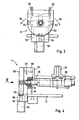
- the apparatus for processing bar material 10, profiles or the like is shown.
- the device 1 has a machine table 12 on which the profiles 10 are mounted with the aid of the profile holder 3.
- the processing unit 6 is, for example, a high-speed tool spindle, a milling cutter, a drill, a planer or the like.
- the processing unit 6 is displaceable parallel to the longitudinal axis 11 of the profile 10, arranged in the direction of the X-axis.
- the processing unit is also movable in the other two spatial axes, ie the Y and Z axes. As a result, a positioning of the processing unit 6 in height or in depth is achieved.
- the processing unit 6 is designed, for example, also pivotable or has an angle drive to edit, for example, the end face 13 of the profile 10.
- a two-part shaft 31,32 is provided as a profile holder 3.
- This division of the shaft has the advantage that relatively short shafts are easy to produce and a majority of these waves form a long profile holder. As a result, a great flexibility of the device is achieved. Also, the production of short waves is easier and less expensive. A majority of the waves is in this case arranged so that they are ever in alignment.
- the two shafts 31, 32 are rigidly connected to one another via the clamping table 36.
- a plurality of supports 15 are provided which bear bearings 14 in which the shaft 30 is mounted.
- the clamping table 36 is connected by support bearings 37 with the shaft.
- the profile holder at each of its ends on a lock 5. This ensures that the profile holder 3, for example, the shaft 30, is optimally maintained in the pivoted position.
- the possible use of the device is further increased if, for example, provided that on a machine table 12 not only a profile holder 3 is provided, but a plurality of profile mounts.
- the advantage is achieved that a processing unit 6 is provided which cooperates, for example, with two profile mounts 3. It is now, for example, a processing possible so that the first profile holder on the profile is changed, while the processing unit 6 to the profile, which is provided on the left profile holder, making operations.
- the high cost of a tool spindle, in particular a high-speed spindle, are thus optimally utilized with the device according to the invention.
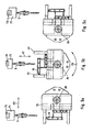
- the lock 5 consists of a locking disc 50 which is attached to the end of the shaft 30.
- the locking disc 50 is formed, for example, circular. But it is also possible that the locking disc 50 consists of a half-disc, in the upper portion 10 at right angles to the disc, a strut 58 or a support is formed, as is indicated for example in Fig. 3. In such a configuration then, for example, the locking disk 50 still acts as a stop 57 for the profile 10 held on the mounting slide 38, wherein the strut 58 carries the stop 57.
- the support plane of the profile is arranged on the clamping device on the device for locking, in particular the locking disc.
- the stop 57 is connected by a strut 58 with the disc 50. With the strut 58, the stop 57 engages over the end bearing 16 and the support 15 in which the shaft 30 is mounted. As indicated in Fig. 4, the stopper 57 is formed almost resting on the shaft 30.
- a lock is provided by an insertable into the disc locking pin 54. Furthermore, it is provided that a servo motor 22 is provided as a pivot drive 20 for stepless adjustment, the has a corresponding brake or clutch to hold the pivoted profile holder in the desired position. Furthermore, it can be provided that the shaft 30 and the profile holder 3 is formed in its end region as a splined shaft, and this spline is determined by corresponding locking positions.
- a locking disc 50 In the formation of the lock 5 by a locking disc 50 is provided that the disc 50 has radial openings 51,52, 53, in which a locking pin 54 is inserted.
- the locking pin 54 is actuated by a working cylinder 55. This can be for example a pneumatic cylinder or an electric drive.
- the pin 54 or the working cylinder 55 is provided here, for example, on the machine table.
- the pin 54 has a conical tip 56. As a result, the retraction of the pin 54 is achieved in the openings 51,52,53 and causes a stable, mechanical connection between the disc and the machine table 12.
- the distance between the openings 51,52 53 at the periphery of the disc 50 is 90 °.
- a 3-sided machining of the clamped profile or bar material is easily possible.
- the openings 51,52,53 with respect to additional openings it is easily possible to realize any other angular adjustment.
- an axial lock is conceivable in which the arrangement of the pin 54 in the axial direction, for example, the shaft 30, takes place.
- a servomotor 22 forms the catch 5. Such a configuration is particularly advantageous when various angle settings are desired.
- the servo motor 22 is then provided, for example, at both ends of the profile holder 3 in order to optimally hold it.
- the servomotor 22 has a clutch or brake to securely lock the position.
- the control acts in common on the servomotor acting on the profile holder, so that a uniform movement and locking of these servomotors is ensured.
- the clamping carriage 38 is shown, which is arranged on the shaft 30.
- the clamping slide 38 is clamped on the shaft 30, so that a pivoting of the shaft 30 also leads to a pivoting of the clamping slide 38.
- the clamping slide 38 is supported on the shaft 30 via the linear bearing 39.
- the clamping slide 38 can be moved manually or pneumatically on the guide shaft 30 and fixed on the shaft 30 in any position. This is particularly advantageous when a profile machining is to be made at locations that are hidden by the clamping jaws 40.
- FIGS. 5a, 5b and 5c the device according to the invention is shown in three different pivoted positions.
- the pivoting device 2 causes a pivoting of the profile holder 3 about an axis which is parallel to the longitudinal axis of the rod material 10.
- the profile holder 3 is pivoted about the axis 34 of the shaft 30.
- the pivoting movement is indicated by the arrow 25.
- operations are performed with the processing unit.
- the processing unit 6 has a mobility at least in the three spatial axes X, Y and Z.
- the X-axis (double arrow 62) is described here by the orientation of the axis 34 and the longitudinal axis 11 of the rod material 10.
- the Y-axis is the horizontal perpendicular to the X-axis.
- the Y-axis is indicated by the double arrow 60. Due to the mobility in the Z direction (arrow 61) a height adjustment is easily possible.
- Fig. 5c is shown that with respect to the position in Fig. 5a, the processing unit 6 is shifted relative to the axis 34 to the right.
- a positioning unit 7 For a movement of the processing unit 6 in the three spatial axes X (62), Y (60) and Z (61), a positioning unit 7 is provided.
- This positioning unit 7 consists of a rail track 70, which is arranged substantially parallel to the longitudinal axis 34 of the shaft 30 of the profile holder 3.
- a carriage 71 On this rail track 70, a carriage 71 is provided, which carries the processing unit 6.
- the drive for the processing unit 6 is provided and a height adjustment (Z-axis) for the processing unit or an adjustability (Y-axis) transverse to the longitudinal axis 34 of the shaft 30.
- the positioning unit 7, which is arranged above the processing table 12 is, but can also be arranged transversely to the longitudinal extension of the profile displaceable or movable.
- the rail track 70 is held on a strut 72, wherein the processing unit 6, for example, edited from above the profile.
- the processing unit 6 for example, edited from above the profile.
- another processing unit 65 is selectively used to edit, for example, the end face of the profile.
- the processing unit 65 optionally has a propulsion in the X direction (62).
- processing unit 6 is typically at least a 3-axis tool spindle. Due to the embodiment of the invention, however, it is achieved that can be dispensed with a more complex mobility of the tool spindle with respect to as versatile as possible processing of the rod material.
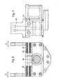
- the profile clamping device 35 is shown in partial section.
- the profile clamping device 35 is arranged on the shaft 30.
- clamping jaws 40,45 are provided, which take the profile on the side of pincers.
- the jaws 40,45 perform a uniform movement.
- a common drive is provided for the drive the two clamping jaws 40, whose movement is indicated by the double arrow 41.
- a pneumatically or hydraulically actuated cylinder acts on a pull plate.
- This tension plate has a slotted guide for the two jaws 40,45.
- a sliding block which is connected to the jaw, engages in the respective slotted guide.
- a movement of the tension plate takes place, and the movements result according to the arrow 41 of the clamping jaws 40, 45.
- a bearing of the clamping jaws 40,45 is provided on the clamping saddle 42. The bearing for this purpose is marked 43.
- the jaws 40 can be used in different basic positions.
- the clamping jaws 40 sit on a Einstellschlitten, and the Einstellschlitten has the backdrop for the slotted guide.
- the clamping jaws are secured with screws on the adjusting slide, for example.
- the Einstellschlitten has notches, which are provided at a shorter distance than the maximum clamping range of the clamping jaws.
- any profile thickness can be kept between a minimum and maximum dimensions.
- the jaws are applied for example pneumatically or hydraulically.
- the application takes place, for example, on said working cylinder.
- a pneumatic impingement may be sufficient, for example, when holding plastic profiles, since in this machining the forces occurring are lower than in a metalworking.
- At high loads for example, provided that a hydraulic admission takes place.
- the working cylinder is in this case acted upon on both sides, a movement of the clamping jaws in the locking or release direction is actuated in each case by the working cylinder.
- a geared motor 23 is provided which acts on the shaft 30 via a toothed belt or V-belt 24.
- a controller 8 For monitoring the movement of the processing unit 6, a controller 8 is provided.
- the processing unit 6 is in this case connected via the data line 81 to the controller 8.
- the controller 8 determines the processing position, that is to say the coordinates along the axes of motion, in this case the three spatial axes.
- the controller 8 with the pivoting drive 20, so the servo motor 22 or the geared motor 23, connected and controls the rotation of the profile.
- the lock 5 is connected to the controller 8. Before rotating the profile for a new machining, the locking is released via this data line so that the pivoting device 2 can pivot the profile 10.
- the lock can be closed again or when using a servomotor 22, a corresponding brake or clutch can be actuated.
- the controller 8 takes into account the new working coordinates for a pivoted profile, since, for example, the controller knows the dimension of the profile, as well as the angle of rotation and adds this information to the machining coordinates on the profile mutatis mutandis and thus determines the new machining position of the tool spindle or the like.
- the device has a machining table and the pivoting device can be mounted on the machining table.
- the pivoting device is mounted, for example, on the base plate of the machining table.
- the pivoting device for example, connections for power and control lines, whereby a smooth integration into the device is possible.
- the signals for the rotation of the profile are transmitted via the control line.
Landscapes
- Engineering & Computer Science (AREA)
- Life Sciences & Earth Sciences (AREA)
- Mechanical Engineering (AREA)
- Wood Science & Technology (AREA)
- Forests & Forestry (AREA)
- Jigs For Machine Tools (AREA)
- Machine Tool Units (AREA)
- Electrical Discharge Machining, Electrochemical Machining, And Combined Machining (AREA)
- Forging (AREA)
- Turning (AREA)
- Load-Engaging Elements For Cranes (AREA)
- Metal Extraction Processes (AREA)
Claims (11)
- Dispositif d'usinage de profilés présentant un axe longitudinal, tels que barres (10) ou autres, constitué d'une unité d'usinage (6) et d'un système de maintien (3) du profilé (10), le système de maintien du profilé pouvant pivoter autour d'un axe disposé parallèlement à l'axe longitudinal (11) du profilé (10), le système de maintien du profilé (3) étant constitué d'un arbre (30) avec au moins un dispositif de saisie des profilés (35) disposé sur ce dernier, l'arbre (30) supportant le dispositif de saisie des profilés (35) et étant partagé en plusieurs parties, en particulier en deux parties, caractérisé en ce que deux arbres (31, 32) sont reliés par un plateau à étau (36).
- Dispositif suivant la revendication 1, caractérisé en ce que ce dispositif présente un système d'arrêt (5) qui immobilise le système de maintien (3) du profilé.
- Dispositif suivant l'une des revendications précédentes, caractérisé en ce que le système d'arrêt (5) comporte un disque (50) avec des ouvertures (51, 52, 53) dans lesquelles une tige de butée (54) peut s'encastrer.
- Dispositif suivant l'une des revendications précédentes, caractérisé en ce que le système d'arrêt (5) est situé à l'extrémité (33) de l'arbre (10).
- Dispositif suivant l'une des revendications 3 et 4, caractérisé en ce que les ouvertures (51, 52, 53) sont décalées l'une par rapport à l'autre d'un angle de 90°.
- Dispositif suivant l'une des revendications précédentes, caractérisé en ce que la commande de pivotement (20) utilise un servomoteur (22).
- Dispositif suivant l'une des revendications précédentes, caractérisé en ce que ce dispositif possède une machine (6) usinant les faces latérales et/ou frontales (13) du profilé (10), cette machine d'usinage (6) pouvant être déplacée parallèlement et/ou dans un plan essentiellement perpendiculaire à l'axe longitudinal (11) du profilé (10).
- Dispositif suivant l'une des revendications précédentes, caractérisé en ce que le dispositif de saisie (35) du profilé possède un coulisseau à étau (38) qui peut être déplacé le long de l'arbre (30).
- Dispositif suivant l'une des revendications précédentes, caractérisé en ce que le dispositif de saisie (35) du profilé possède des mâchoires (40), qui peuvent être actionnées par des moyens pneumatiques, hydrauliques ou électriques et qui maintiennent le profilé (10) à la manière d'une pince sur le côté.
- Dispositif suivant l'une des revendications précédentes, caractérisé en ce que les deux mâchoires (40) réalisent un même mouvement de serrage (41) pour la saisie centrée du profilé (10).
- Dispositif suivant l'une des revendications précédentes, caractérisé en ce que ce dispositif possède un plateau d'usinage et le système de pivotement peut être monté sur ce plateau d'usinage.
Applications Claiming Priority (2)
| Application Number | Priority Date | Filing Date | Title |
|---|---|---|---|
| DE29601808U | 1996-02-04 | ||
| DE29601808U DE29601808U1 (de) | 1996-02-04 | 1996-02-04 | Vorrichtung zum Bearbeiten von Stangenmaterial, Profilen u.dgl. |
Publications (3)
| Publication Number | Publication Date |
|---|---|
| EP0787560A1 EP0787560A1 (fr) | 1997-08-06 |
| EP0787560B1 EP0787560B1 (fr) | 2002-04-10 |
| EP0787560B2 true EP0787560B2 (fr) | 2007-01-03 |
Family
ID=8018909
Family Applications (1)
| Application Number | Title | Priority Date | Filing Date |
|---|---|---|---|
| EP97100989A Expired - Lifetime EP0787560B2 (fr) | 1996-02-04 | 1997-01-23 | Dispositif d'usinage des barres, des profilés et similaire |
Country Status (4)
| Country | Link |
|---|---|
| US (1) | US5957638A (fr) |
| EP (1) | EP0787560B2 (fr) |
| AT (1) | ATE215866T1 (fr) |
| DE (2) | DE29601808U1 (fr) |
Families Citing this family (10)
| Publication number | Priority date | Publication date | Assignee | Title |
|---|---|---|---|---|
| DE59906051D1 (de) * | 1998-02-05 | 2003-07-31 | Bernhard Eisenbach | Vorrichtung zur mehrseitigen Bearbeitung von Hohlprofilen |
| IT1313224B1 (it) * | 1999-07-02 | 2002-06-17 | Unifor Spa | Dispositivo di serraggio e di posizionamento di pezzi in lavorazionedi forma allungata e sottile. |
| CN1209225C (zh) * | 2000-02-01 | 2005-07-06 | 俄玫机有限公司卢森堡卢加诺分公司 | 实施机械加工的系统 |
| DE10030865B4 (de) * | 2000-06-23 | 2004-09-02 | Eisenbach, Bernhard, Dipl.-Ing. | Spanneinrichtung für Werkstücke, wie Fenster- oder Türprofile oder sonstige langgestreckte Profile |
| ITMO20030004A1 (it) * | 2003-01-13 | 2004-07-14 | Emmegi Spa | Macchina utensile. |
| EP1555084A1 (fr) * | 2004-01-13 | 2005-07-20 | Mubea Systems, Société Anonyme | Machine-outil avec dispositifs de serrage coulissants en longueur avec des moyens moteurs propres |
| CN109175452A (zh) * | 2018-10-22 | 2019-01-11 | 森鹤乐器股份有限公司 | 一种总档支架的加工设备 |
| CN111823023B (zh) * | 2020-08-28 | 2025-02-07 | 焦作市强信粉末冶金科技有限公司 | 一种三维旋转工装 |
| CN117484245A (zh) * | 2023-11-23 | 2024-02-02 | 广东普拉迪科技股份有限公司 | 长条型材上料装置及长条型材机械加工生产线 |
| CN119819968A (zh) * | 2025-03-17 | 2025-04-15 | 浙江品峰机械有限公司 | 不锈钢烘板加工用矫正穿孔设备及方法 |
Citations (1)
| Publication number | Priority date | Publication date | Assignee | Title |
|---|---|---|---|---|
| US4502457A (en) † | 1982-08-27 | 1985-03-05 | Raul C. Montoya | Universal multiple angle work piece holder with multiple tool conversion features |
Family Cites Families (11)
| Publication number | Priority date | Publication date | Assignee | Title |
|---|---|---|---|---|
| DE245103C (fr) * | ||||
| US1498660A (en) * | 1919-12-29 | 1924-06-24 | Columbia Axle Company | Work-holding mechanism |
| US2651975A (en) * | 1949-05-11 | 1953-09-15 | Soloff Milton | Internal carving machine |
| US3371580A (en) * | 1966-01-21 | 1968-03-05 | Mc Donnell Douglas Corp | Multiple axis milling machine and fixture |
| US3746459A (en) * | 1971-03-24 | 1973-07-17 | Overmyer Mould Co | Apparatus for drilling escape and vent holes in die molds |
| US3918145A (en) * | 1974-07-08 | 1975-11-11 | Frank R Oglivie | Automatic machine tool |
| DE2915380A1 (de) * | 1979-04-14 | 1980-10-16 | Hegenscheidt Gmbh Wilhelm | Verfahren zum einspannen rohrfoermiger werkstuecke auf tiefbohrmaschinen |
| FR2540023B1 (fr) * | 1983-02-01 | 1986-07-25 | Dufieux Machine Outil | Dispositif destine a deplacer, devant des moyens d'usinage et dans le sens de sa longueur, un profile a usiner |
| JPS61288908A (ja) * | 1985-06-14 | 1986-12-19 | Hidetoshi Okawa | 中空材木の製造装置 |
| CA2012117C (fr) * | 1990-02-12 | 2001-05-01 | John Ingvar Emanuel Johansson | Bras manipulateurs devant etre utilise conjointement avec un robot industriel |
| DE4204519A1 (de) * | 1992-02-15 | 1993-08-19 | Bernhard Eisenbach | Vorrichtung zur mehrseitigen bearbeitung von hohlprofilen |
-
1996
- 1996-02-04 DE DE29601808U patent/DE29601808U1/de not_active Expired - Lifetime
-
1997
- 1997-01-23 EP EP97100989A patent/EP0787560B2/fr not_active Expired - Lifetime
- 1997-01-23 DE DE59706922T patent/DE59706922D1/de not_active Expired - Fee Related
- 1997-01-23 AT AT97100989T patent/ATE215866T1/de not_active IP Right Cessation
- 1997-02-04 US US08/795,310 patent/US5957638A/en not_active Expired - Fee Related
Patent Citations (1)
| Publication number | Priority date | Publication date | Assignee | Title |
|---|---|---|---|---|
| US4502457A (en) † | 1982-08-27 | 1985-03-05 | Raul C. Montoya | Universal multiple angle work piece holder with multiple tool conversion features |
Non-Patent Citations (3)
| Title |
|---|
| Prospekt Matec 30-L † |
| Prospekt NIKKEN LOCK-JAW SAX-4MT-120 † |
| Prospekt Tekna TK 426 † |
Also Published As
| Publication number | Publication date |
|---|---|
| EP0787560A1 (fr) | 1997-08-06 |
| DE59706922D1 (de) | 2002-05-16 |
| EP0787560B1 (fr) | 2002-04-10 |
| ATE215866T1 (de) | 2002-04-15 |
| DE29601808U1 (de) | 1996-04-11 |
| US5957638A (en) | 1999-09-28 |
Similar Documents
| Publication | Publication Date | Title |
|---|---|---|
| EP1188511B1 (fr) | Machine-outil avec un chariot porte-outil motorisé | |
| DE4113629C2 (de) | Reihenbohr- und Fräsmaschine | |
| CH629407A5 (de) | Werkzeugmaschine. | |
| EP1260310A2 (fr) | Machine-outil pour l'usinage d'une pièce en forme de barre | |
| EP0130309B1 (fr) | Machines à travailler le bois | |
| EP0787560B2 (fr) | Dispositif d'usinage des barres, des profilés et similaire | |
| DE19919645A1 (de) | Werkzeugmaschine mit Werkzeugspindel und Revolverkopf | |
| EP1286794B1 (fr) | Machine de laminage a froid | |
| EP2425921A2 (fr) | Dispositif destiné au traitement de pièces à usiner | |
| DE19516263A1 (de) | CNC-gesteuerte Holzbearbeitungsanlage, insbesondere für lange Werkstücke wie Balken | |
| EP1651381B1 (fr) | Machine-outil avec systeme de fixation des deux cotes | |
| DE69126135T2 (de) | Portalwerkzeugmaschine | |
| DE10330909B4 (de) | Werkzeugmaschine und Verfahren zur spanabhebenden Bearbeitung von Werkstücken | |
| EP1025953A1 (fr) | Machine-outil | |
| DE20010717U1 (de) | Multifunktionale Bohrmaschine | |
| DE19911156C2 (de) | Drehmaschine zur Bearbeitung von wellenförmigen Werkstücken | |
| DE2636986A1 (de) | Drehbank | |
| AT521951B1 (de) | Werkzeugmaschine | |
| EP0813941B2 (fr) | Machine-outil pour l'usinage de pièces allongées | |
| DE10145674B4 (de) | Werkzeugmaschine zur Bearbeitung eines stangenförmigen Werkstücks | |
| DE19831284C2 (de) | Abbundanlage zur Bearbeitung von Strangmaterial | |
| EP1577040A1 (fr) | Dispositif d'usinage de pièces, notamment pour des pièces pourvues de dents | |
| DE8912243U1 (de) | Kurzhub-Werkzeugmaschine mit einem an einem Maschinengestell verfahrbar gelagerten Bohr- und Frässpindelstock | |
| DE9006627U1 (de) | Werkzeugmaschine | |
| DE952583C (de) | Fraesmaschine, insbesondere zum Herstellen von Profillehren |
Legal Events
| Date | Code | Title | Description |
|---|---|---|---|
| PUAI | Public reference made under article 153(3) epc to a published international application that has entered the european phase |
Free format text: ORIGINAL CODE: 0009012 |
|
| AK | Designated contracting states |
Kind code of ref document: A1 Designated state(s): AT DE FR GB IT |
|
| 17P | Request for examination filed |
Effective date: 19971015 |
|
| 17Q | First examination report despatched |
Effective date: 20000518 |
|
| GRAG | Despatch of communication of intention to grant |
Free format text: ORIGINAL CODE: EPIDOS AGRA |
|
| GRAG | Despatch of communication of intention to grant |
Free format text: ORIGINAL CODE: EPIDOS AGRA |
|
| GRAH | Despatch of communication of intention to grant a patent |
Free format text: ORIGINAL CODE: EPIDOS IGRA |
|
| REG | Reference to a national code |
Ref country code: GB Ref legal event code: IF02 |
|
| GRAH | Despatch of communication of intention to grant a patent |
Free format text: ORIGINAL CODE: EPIDOS IGRA |
|
| GRAA | (expected) grant |
Free format text: ORIGINAL CODE: 0009210 |
|
| AK | Designated contracting states |
Kind code of ref document: B1 Designated state(s): AT DE FR GB IT |
|
| REF | Corresponds to: |
Ref document number: 215866 Country of ref document: AT Date of ref document: 20020415 Kind code of ref document: T |
|
| REF | Corresponds to: |
Ref document number: 59706922 Country of ref document: DE Date of ref document: 20020516 |
|
| GBT | Gb: translation of ep patent filed (gb section 77(6)(a)/1977) |
Effective date: 20020702 |
|
| ET | Fr: translation filed | ||
| PLBQ | Unpublished change to opponent data |
Free format text: ORIGINAL CODE: EPIDOS OPPO |
|
| PLBI | Opposition filed |
Free format text: ORIGINAL CODE: 0009260 |
|
| PLBF | Reply of patent proprietor to notice(s) of opposition |
Free format text: ORIGINAL CODE: EPIDOS OBSO |
|
| 26 | Opposition filed |
Opponent name: TEKNA S.R.L Effective date: 20030107 |
|
| PLAX | Notice of opposition and request to file observation + time limit sent |
Free format text: ORIGINAL CODE: EPIDOSNOBS2 |
|
| PLBB | Reply of patent proprietor to notice(s) of opposition received |
Free format text: ORIGINAL CODE: EPIDOSNOBS3 |
|
| PUAH | Patent maintained in amended form |
Free format text: ORIGINAL CODE: 0009272 |
|
| STAA | Information on the status of an ep patent application or granted ep patent |
Free format text: STATUS: PATENT MAINTAINED AS AMENDED |
|
| 27A | Patent maintained in amended form |
Effective date: 20070103 |
|
| AK | Designated contracting states |
Kind code of ref document: B2 Designated state(s): AT DE FR GB IT |
|
| GBTA | Gb: translation of amended ep patent filed (gb section 77(6)(b)/1977) | ||
| PGFP | Annual fee paid to national office [announced via postgrant information from national office to epo] |
Ref country code: DE Payment date: 20070321 Year of fee payment: 11 |
|
| ET3 | Fr: translation filed ** decision concerning opposition | ||
| PGFP | Annual fee paid to national office [announced via postgrant information from national office to epo] |
Ref country code: GB Payment date: 20080123 Year of fee payment: 12 Ref country code: IT Payment date: 20080126 Year of fee payment: 12 |
|
| PGFP | Annual fee paid to national office [announced via postgrant information from national office to epo] |
Ref country code: AT Payment date: 20080111 Year of fee payment: 12 |
|
| PGFP | Annual fee paid to national office [announced via postgrant information from national office to epo] |
Ref country code: FR Payment date: 20080118 Year of fee payment: 12 |
|
| PG25 | Lapsed in a contracting state [announced via postgrant information from national office to epo] |
Ref country code: DE Free format text: LAPSE BECAUSE OF NON-PAYMENT OF DUE FEES Effective date: 20080801 |
|
| PLAB | Opposition data, opponent's data or that of the opponent's representative modified |
Free format text: ORIGINAL CODE: 0009299OPPO |
|
| GBPC | Gb: european patent ceased through non-payment of renewal fee |
Effective date: 20090123 |
|
| PG25 | Lapsed in a contracting state [announced via postgrant information from national office to epo] |
Ref country code: AT Free format text: LAPSE BECAUSE OF NON-PAYMENT OF DUE FEES Effective date: 20090123 |
|
| REG | Reference to a national code |
Ref country code: FR Ref legal event code: ST Effective date: 20091030 |
|
| PG25 | Lapsed in a contracting state [announced via postgrant information from national office to epo] |
Ref country code: GB Free format text: LAPSE BECAUSE OF NON-PAYMENT OF DUE FEES Effective date: 20090123 |
|
| PG25 | Lapsed in a contracting state [announced via postgrant information from national office to epo] |
Ref country code: FR Free format text: LAPSE BECAUSE OF NON-PAYMENT OF DUE FEES Effective date: 20090202 |
|
| PG25 | Lapsed in a contracting state [announced via postgrant information from national office to epo] |
Ref country code: IT Free format text: LAPSE BECAUSE OF NON-PAYMENT OF DUE FEES Effective date: 20090123 |