EP0787955A2 - Revêtement pour radiateur à plaques - Google Patents
Revêtement pour radiateur à plaques Download PDFInfo
- Publication number
- EP0787955A2 EP0787955A2 EP96201927A EP96201927A EP0787955A2 EP 0787955 A2 EP0787955 A2 EP 0787955A2 EP 96201927 A EP96201927 A EP 96201927A EP 96201927 A EP96201927 A EP 96201927A EP 0787955 A2 EP0787955 A2 EP 0787955A2
- Authority
- EP
- European Patent Office
- Prior art keywords
- panel
- edge
- hook
- cutouts
- mounting
- Prior art date
- Legal status (The legal status is an assumption and is not a legal conclusion. Google has not performed a legal analysis and makes no representation as to the accuracy of the status listed.)
- Granted
Links
Images


Classifications
-
- F—MECHANICAL ENGINEERING; LIGHTING; HEATING; WEAPONS; BLASTING
- F24—HEATING; RANGES; VENTILATING
- F24D—DOMESTIC- OR SPACE-HEATING SYSTEMS, e.g. CENTRAL HEATING SYSTEMS; DOMESTIC HOT-WATER SUPPLY SYSTEMS; ELEMENTS OR COMPONENTS THEREFOR
- F24D19/00—Details
- F24D19/06—Casings, cover lids or ornamental panels, for radiators
- F24D19/065—Grids attached to the radiator and covering its top
-
- F—MECHANICAL ENGINEERING; LIGHTING; HEATING; WEAPONS; BLASTING
- F24—HEATING; RANGES; VENTILATING
- F24D—DOMESTIC- OR SPACE-HEATING SYSTEMS, e.g. CENTRAL HEATING SYSTEMS; DOMESTIC HOT-WATER SUPPLY SYSTEMS; ELEMENTS OR COMPONENTS THEREFOR
- F24D19/00—Details
- F24D19/06—Casings, cover lids or ornamental panels, for radiators
Definitions
- the invention relates to a panel for a panel radiator, consisting of a front panel, two side panels and an upper, provided with cross bars cover grille and fasteners clampable to the panel radiator.
- Panels for panel radiators with different types of mounting are known in numerous designs.
- To attach the front panel is such.
- EP 0 335 938 A1 the front plate can also be glued to the front surface of the meandering convector plate of the plate heating element.
- Side panels can e.g. B. according to DE 90 07 630 U1 on bent ends of the cover plate and attached to the radiator.
- DE 43 34 705 C1 describes cover grilles made of lattice bars which are welded onto cross bars, the cover grid resting on shoulders which are clamped onto the upper edge of the convector plate.
- the side panels are fastened with hook-shaped fastening elements which are clamped onto the upper or lower edge of the convector plate and to which the side panels can be screwed.
- the known types of fastening for the cladding elements are generally complex to manufacture and require complicated assembly using tools.
- the fastening methods must also be individually adapted to the different sizes of the panel radiators.
- the invention is therefore based on the object to develop a fastening for the cladding elements, which can be attached quickly with simple fastening elements and without tools, and which can also be used for renovation work. The like can be quickly removed from the radiator.
- the new fastening initially has the advantage that only upper and lower fastening hooks are required for mounting on the radiator.
- the upper fastening hooks are used on the one hand to attach the front panel to the panel radiator, and on the other hand to support the grille.
- the cover grille is in turn connected to the front plate by the engagement of the cross bars in the holes in the upper mounting bracket and the two side panels are fastened to the front plate and locked to the cover grille with a hook clamp.
- the installation is quick and easy for laymen.
- Another advantage is that the cladding elements can be combined for panel radiators of different sizes.
- the attachment can also be applied to plate radiators of different designs from different manufacturers.
- the design of the fasteners can be modified.
- the horizontal mounting strips can be screwed, welded or clamped onto the front panel, they are preferably fastened by gluing with edges lying flat against the rear surface of the front panel.
- a favorable locking of the front panel can be achieved in that the cutouts in the upper mounting strip have lateral edge cutouts and the upper fastening hooks have lateral projections and the upper edge of the cutouts rests on a shoulder of the fastening hook in question at such a height that the projections of the fastening hook behind the projections of the cutouts.
- the lower fastening hooks reach behind the side edges of the vertically arranged cutouts of the lower bracket strip with side legs.
- the leg of the fastening hook comprising the upper and lower edge of the plate heating element is provided with a clamping screw which can be screwed forward against the plate heating element.
- the front leg which grips the mounting strip, is tightened and braces the mounting strip and thus the front panel with the plate heater.
- the vertical mounting strips of the front plate are expediently provided with a support hook in the lower area, on each of which a hook-shaped recess in the edge bend of the side panel can be plugged in at an incline and when the side panel is folded against the panel heater, the edge bend is pressed under the mounting tongues.
- the cross bars of the grille protrude on one side and protrude into the holes in the upper mounting plate, one of which is designed as a round hole and the other as tolerance-compensating elongated holes.
- the inward-pointing, spring-loaded hook clamp of the side panel has upwardly projecting shoulders, which lie laterally against the bars in between and form barbs for the relevant crossbar of the cover screen.
- the upper edge of the side panel is bent inwards in an U-shape and forms an upper stop for the grille bars of the grille.
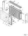
- the paneling of the panel heating element 1 shown in FIG. 1 serves a front panel 2, two side panels 3 and a cover grid 4.
- the paneling elements consist of sheet metal and are provided with a coat of paint.
- the upper mounting strip 6 is provided with a plurality of cutouts 13 distributed over its length, edge cutouts 14 being provided on the sides.
- the cutouts 13 are used to insert fastening hooks 15.
- the fastening hooks 15, as shown in FIG. 4, are designed like saddles and are attached to the upper edge 16 of the plate heating element 1.
- a front leg 17 is profiled with lateral projections 18 so that it fits into the corresponding profile of the cutouts 13.
- the other rear leg 19, which lies on the back of the plate heater 1, is provided with a clamping screw 20 which can be screwed forward against the plate heater 1.
- the lower bracket bar 7 is above it Length provided with cutouts 21, which are, however, rectangular and arranged upright.
- a fastening hook 22 assigned to the cutouts 21 is shown in FIG. 5. This is designed like a bow and is inserted from below over the lower edge 23 of the plate heater 1.
- the front leg 24 forms with side legs 25 an approximately rectangular profile, so that the leg 24 can be inserted into the cutout 21 in an upright position and after turning the fastening hook 22 by 90 °, the side legs 25 engage behind the lower mounting leg 7.
- the rear leg 26 is provided with a clamping screw 27 which can be screwed forward against the panel heating element 1.
- two or more lower fastening hooks 22 are first inserted into the cutouts 21 of the lower mounting strip 7 and rotated by 90 °. Furthermore, two or more upper fastening hooks 15 are placed on the upper edge 16 of the plate heater 1. The front plate 2 is then plugged with its upper mounting strip 6 onto the front legs 17 of the upper fastening hooks 15 and hung in until the upper edge 28 of the cutouts 13 rests on a shoulder 29 formed by the front legs 17. Then the clamping screws 20 are screwed against the plate heater 1, so that the mounting bracket 7 and thus the front panel 2 is clamped to the plate heater 1. Then the lower fastening hooks 22 are inserted from below over the lower edge 23 of the panel heater 1, and by means of the tensioning screws 27 there is a lower tension between the front panel 2 and panel heater 1. The front panel 2 is thus firmly attached to the panel heater 1.
- the cover 4 is attached.
- This consists of a plurality of parallel arranged lattice bars 30 made of flat iron or bent in the shape of a drop in cross section Metal strips that are welded onto cross bars 31.
- holes 32, 33 are arranged in the upper mounting bar 6 of the front plate 2 above the cutouts 13, one of which is designed as a round hole 32 and the other as tolerance-compensating elongated holes 33.
- support legs 34 with incisions or cutouts 35, in which cross bars 31 rest and prevent the cover grid 4 from shifting perpendicular to the radiator surface.
- the cross bars 31 protrude on the front side so far that they engage in the holes 31, 33 and the corresponding lattice bars 30 come to lie in the cutouts 35.
- the side panels 3 are attached.
- the lateral vertical mounting strips 8 and a front edge bend 35 are provided with cooperating fastening elements.
- the mounting strips 8 are provided in the lower region with a support hook 36 which projects at right angles and has a slot into which the slot 37 of a cutout 38 engages in the edge bend 35.
- one or more tongues 39 are provided on the mounting strip 8, under which the edge bend 35 of the side panel 3 is pushed.
- the side cover 3 is first hooked in at an incline at the bottom and then folded up, the edge bend 35 being pushed under the tongues 39. To lock the folded side panel 3, this is provided with a hook clamp 40, which comes into engagement with a crossbar 31 of the grille 4.
- the resilient hook clamp 40 is attached to the upper end of the side panel 3 and is directed inwards.
- the distance of this cross bar 31 from the ends of the bars 30 is dimensioned such that the hook clamp 40 grips the cross bar 31.
- the barb-like locking is done with the help of two upstanding shoulders 41, which have an inclined sliding surface when snapped in and form a restricted area.
- the upper edge of the side cover 3 is bent inward in an approximately U-shaped manner and forms an upper stop 42 for the grid bars 30 of the cover grid 3 in the latched position.
Landscapes
- Engineering & Computer Science (AREA)
- Physics & Mathematics (AREA)
- Thermal Sciences (AREA)
- Chemical & Material Sciences (AREA)
- Combustion & Propulsion (AREA)
- Mechanical Engineering (AREA)
- General Engineering & Computer Science (AREA)
- Domestic Hot-Water Supply Systems And Details Of Heating Systems (AREA)
Applications Claiming Priority (2)
| Application Number | Priority Date | Filing Date | Title |
|---|---|---|---|
| DE29601772U DE29601772U1 (de) | 1996-02-02 | 1996-02-02 | Verkleidung für einen Plattenheizkörper |
| DE29601772U | 1996-02-02 |
Publications (3)
| Publication Number | Publication Date |
|---|---|
| EP0787955A2 true EP0787955A2 (fr) | 1997-08-06 |
| EP0787955A3 EP0787955A3 (fr) | 1998-03-25 |
| EP0787955B1 EP0787955B1 (fr) | 2000-03-29 |
Family
ID=8018884
Family Applications (1)
| Application Number | Title | Priority Date | Filing Date |
|---|---|---|---|
| EP96201927A Expired - Lifetime EP0787955B1 (fr) | 1996-02-02 | 1996-07-09 | Revêtement pour radiateur à plaques |
Country Status (3)
| Country | Link |
|---|---|
| EP (1) | EP0787955B1 (fr) |
| DE (2) | DE29601772U1 (fr) |
| DK (1) | DK0787955T3 (fr) |
Cited By (6)
| Publication number | Priority date | Publication date | Assignee | Title |
|---|---|---|---|---|
| GB2373316A (en) * | 2001-02-05 | 2002-09-18 | Rowland Hill | Radiator covers or cabinets |
| EP1139031A3 (fr) * | 2000-03-29 | 2003-05-21 | Peter Und Annette Gabanyi | Dispositif de climatisation d'espace |
| FR2880412A1 (fr) * | 2005-01-06 | 2006-07-07 | Fabrice Heroult Finance Soc Ci | Systeme d'habillage d'un radiateur notamment de chauffage central ou electrique. |
| WO2009112860A1 (fr) * | 2008-03-13 | 2009-09-17 | Roco (Europe) Limited | Ensemble radiateur |
| FR2937121A1 (fr) * | 2008-10-13 | 2010-04-16 | Jean Michel Perrier | Radiateur et equipement de chauffage de batiment. |
| EP2770265A1 (fr) * | 2013-02-26 | 2014-08-27 | Ulamo Holding BV | Support pour une unité de circulation d'air |
Families Citing this family (3)
| Publication number | Priority date | Publication date | Assignee | Title |
|---|---|---|---|---|
| FR2760828B1 (fr) * | 1997-03-13 | 1999-05-28 | Finimetal Societe De Finissage | Radiateur de chauffage a surface de contact portee a temperature moderee |
| DE29919613U1 (de) * | 1999-11-08 | 2000-02-03 | Ulamo Beheer B.V., Ulft | Heizkörperverkleidung |
| DE202007015252U1 (de) | 2007-10-31 | 2008-01-24 | Ulamo Holding B.V. | Befestigungseinrichtung |
Family Cites Families (8)
| Publication number | Priority date | Publication date | Assignee | Title |
|---|---|---|---|---|
| DE7004981U (de) * | 1970-02-13 | 1970-06-11 | Kufferath Geb | Befestigungselement fuer heizkoerper-verkleidungen u. dgl. |
| DE2127004A1 (de) * | 1971-06-01 | 1972-12-14 | Pinter, Bernhard, 5063 Overath | Heizkörperverkleidung |
| DE7936419U1 (de) * | 1979-12-22 | 1980-04-24 | Wibo-Werk Ing. Wilhelm Bottermann, 2000 Hamburg | Keramische heizkoerperverkleidungs- platte |
| DE9007630U1 (de) * | 1989-03-10 | 1993-06-24 | Kermi GmbH, 8350 Plattling | Heizkörperverkleidung |
| DE4334705C1 (de) * | 1993-10-12 | 1995-04-13 | Ulamo Beheer Bv | Abdeckgitter für Plattenheizkörper |
| DE4408242C1 (de) * | 1994-03-11 | 1995-05-04 | Ulamo Beheer Bv | Randabdeckung für Flachheizkörper |
| DE9411955U1 (de) * | 1994-07-23 | 1994-09-29 | Baufa-Werke GmbH, 58708 Menden | Flachheizkörper |
| DE29511988U1 (de) * | 1995-07-27 | 1995-09-07 | Ulamo Beheer B.V., Ulft | Vorrichtung zur Befestigung einer Frontplatte an einem Heizkörper |
-
1996
- 1996-02-02 DE DE29601772U patent/DE29601772U1/de not_active Expired - Lifetime
- 1996-07-09 DK DK96201927T patent/DK0787955T3/da active
- 1996-07-09 DE DE59604837T patent/DE59604837D1/de not_active Expired - Fee Related
- 1996-07-09 EP EP96201927A patent/EP0787955B1/fr not_active Expired - Lifetime
Cited By (6)
| Publication number | Priority date | Publication date | Assignee | Title |
|---|---|---|---|---|
| EP1139031A3 (fr) * | 2000-03-29 | 2003-05-21 | Peter Und Annette Gabanyi | Dispositif de climatisation d'espace |
| GB2373316A (en) * | 2001-02-05 | 2002-09-18 | Rowland Hill | Radiator covers or cabinets |
| FR2880412A1 (fr) * | 2005-01-06 | 2006-07-07 | Fabrice Heroult Finance Soc Ci | Systeme d'habillage d'un radiateur notamment de chauffage central ou electrique. |
| WO2009112860A1 (fr) * | 2008-03-13 | 2009-09-17 | Roco (Europe) Limited | Ensemble radiateur |
| FR2937121A1 (fr) * | 2008-10-13 | 2010-04-16 | Jean Michel Perrier | Radiateur et equipement de chauffage de batiment. |
| EP2770265A1 (fr) * | 2013-02-26 | 2014-08-27 | Ulamo Holding BV | Support pour une unité de circulation d'air |
Also Published As
| Publication number | Publication date |
|---|---|
| DE59604837D1 (de) | 2000-05-04 |
| EP0787955B1 (fr) | 2000-03-29 |
| EP0787955A3 (fr) | 1998-03-25 |
| DK0787955T3 (da) | 2000-07-31 |
| DE29601772U1 (de) | 1996-03-28 |
Similar Documents
| Publication | Publication Date | Title |
|---|---|---|
| DE69514817T2 (de) | Tragvorrichtung für abgehängte decken | |
| EP2023050A1 (fr) | Habillage mural ou plafonnier doté d'un dispositif de chauffage ou de refroidissement | |
| DE202021104616U1 (de) | Regalpreisleiste | |
| EP0787955B1 (fr) | Revêtement pour radiateur à plaques | |
| DE3841179C2 (fr) | ||
| DE29511988U1 (de) | Vorrichtung zur Befestigung einer Frontplatte an einem Heizkörper | |
| DE202012009700U1 (de) | Dachhaken | |
| DE202023100433U1 (de) | Montagesystem | |
| EP0162063B1 (fr) | Dispositif de fixation | |
| EP1098145B1 (fr) | Couverture de radiateur | |
| DE10105483C2 (de) | Zaun mit Gitterelementen | |
| DE20316563U1 (de) | Heizkörperverkleidung | |
| DE102020113138A1 (de) | Fassaden- oder Dachverkleidung mit Verkleidungselementen | |
| DE29611333U1 (de) | Befestigungselement mit Träger | |
| EP1584874B1 (fr) | Dispositif de fixation pour une plaque frontale | |
| DE20006710U1 (de) | Halterung für an einem Gebäude vorzuhängende, längliche Gegenstände, insbesondere Dachentwässerungsrinnen | |
| EP1400759B1 (fr) | Elément de fixation | |
| DE8705309U1 (de) | Befestigungselement | |
| DE4204706A1 (de) | Haltersystem fuer sockelleisten zum fixieren und abdecken von heizkoerperanbindeleitungen hinter einer speziellen sockelleiste | |
| DE9210454U1 (de) | Verkaufshilfe | |
| DE202023100439U1 (de) | Befestigungsklemme | |
| DE202016003333U1 (de) | Befestigungssystem | |
| DE19910690A1 (de) | Halter für Röhrenradiatoren | |
| DE9421446U1 (de) | Wandkonsole für Heizkörper | |
| DE9409923U1 (de) | Traggestell für Regalböden |
Legal Events
| Date | Code | Title | Description |
|---|---|---|---|
| PUAI | Public reference made under article 153(3) epc to a published international application that has entered the european phase |
Free format text: ORIGINAL CODE: 0009012 |
|
| AK | Designated contracting states |
Kind code of ref document: A2 Designated state(s): BE DE DK FR GB LU NL |
|
| PUAL | Search report despatched |
Free format text: ORIGINAL CODE: 0009013 |
|
| AK | Designated contracting states |
Kind code of ref document: A3 Designated state(s): BE DE DK FR GB LU NL |
|
| 17P | Request for examination filed |
Effective date: 19980302 |
|
| GRAG | Despatch of communication of intention to grant |
Free format text: ORIGINAL CODE: EPIDOS AGRA |
|
| GRAG | Despatch of communication of intention to grant |
Free format text: ORIGINAL CODE: EPIDOS AGRA |
|
| GRAH | Despatch of communication of intention to grant a patent |
Free format text: ORIGINAL CODE: EPIDOS IGRA |
|
| 17Q | First examination report despatched |
Effective date: 19990622 |
|
| GRAH | Despatch of communication of intention to grant a patent |
Free format text: ORIGINAL CODE: EPIDOS IGRA |
|
| GRAA | (expected) grant |
Free format text: ORIGINAL CODE: 0009210 |
|
| AK | Designated contracting states |
Kind code of ref document: B1 Designated state(s): BE DE DK FR GB LU NL |
|
| GBT | Gb: translation of ep patent filed (gb section 77(6)(a)/1977) |
Effective date: 20000411 |
|
| REF | Corresponds to: |
Ref document number: 59604837 Country of ref document: DE Date of ref document: 20000504 |
|
| PG25 | Lapsed in a contracting state [announced via postgrant information from national office to epo] |
Ref country code: LU Free format text: LAPSE BECAUSE OF NON-PAYMENT OF DUE FEES Effective date: 20000709 |
|
| ET | Fr: translation filed | ||
| PG25 | Lapsed in a contracting state [announced via postgrant information from national office to epo] |
Ref country code: BE Free format text: LAPSE BECAUSE OF NON-PAYMENT OF DUE FEES Effective date: 20000731 |
|
| REG | Reference to a national code |
Ref country code: DK Ref legal event code: T3 |
|
| PLBE | No opposition filed within time limit |
Free format text: ORIGINAL CODE: 0009261 |
|
| STAA | Information on the status of an ep patent application or granted ep patent |
Free format text: STATUS: NO OPPOSITION FILED WITHIN TIME LIMIT |
|
| BERE | Be: lapsed |
Owner name: ULAMO BEHEER B.V. Effective date: 20000731 |
|
| 26N | No opposition filed | ||
| REG | Reference to a national code |
Ref country code: GB Ref legal event code: IF02 |
|
| PGFP | Annual fee paid to national office [announced via postgrant information from national office to epo] |
Ref country code: GB Payment date: 20030616 Year of fee payment: 8 |
|
| PGFP | Annual fee paid to national office [announced via postgrant information from national office to epo] |
Ref country code: NL Payment date: 20030721 Year of fee payment: 8 Ref country code: FR Payment date: 20030721 Year of fee payment: 8 |
|
| PGFP | Annual fee paid to national office [announced via postgrant information from national office to epo] |
Ref country code: DK Payment date: 20030729 Year of fee payment: 8 |
|
| PGFP | Annual fee paid to national office [announced via postgrant information from national office to epo] |
Ref country code: DE Payment date: 20030930 Year of fee payment: 8 |
|
| PG25 | Lapsed in a contracting state [announced via postgrant information from national office to epo] |
Ref country code: GB Free format text: LAPSE BECAUSE OF NON-PAYMENT OF DUE FEES Effective date: 20040709 |
|
| PG25 | Lapsed in a contracting state [announced via postgrant information from national office to epo] |
Ref country code: DK Free format text: LAPSE BECAUSE OF NON-PAYMENT OF DUE FEES Effective date: 20040802 |
|
| PG25 | Lapsed in a contracting state [announced via postgrant information from national office to epo] |
Ref country code: NL Free format text: LAPSE BECAUSE OF NON-PAYMENT OF DUE FEES Effective date: 20050201 Ref country code: DE Free format text: LAPSE BECAUSE OF NON-PAYMENT OF DUE FEES Effective date: 20050201 |
|
| GBPC | Gb: european patent ceased through non-payment of renewal fee |
Effective date: 20040709 |
|
| REG | Reference to a national code |
Ref country code: DK Ref legal event code: EBP |
|
| PG25 | Lapsed in a contracting state [announced via postgrant information from national office to epo] |
Ref country code: FR Free format text: LAPSE BECAUSE OF NON-PAYMENT OF DUE FEES Effective date: 20050331 |
|
| NLV4 | Nl: lapsed or anulled due to non-payment of the annual fee |
Effective date: 20050201 |
|
| REG | Reference to a national code |
Ref country code: FR Ref legal event code: ST |