EP0788134B1 - Ablenkjoch und Ablenkjoch enthaltende Farbkathodenstrahlröhre - Google Patents
Ablenkjoch und Ablenkjoch enthaltende Farbkathodenstrahlröhre Download PDFInfo
- Publication number
- EP0788134B1 EP0788134B1 EP97106570A EP97106570A EP0788134B1 EP 0788134 B1 EP0788134 B1 EP 0788134B1 EP 97106570 A EP97106570 A EP 97106570A EP 97106570 A EP97106570 A EP 97106570A EP 0788134 B1 EP0788134 B1 EP 0788134B1
- Authority
- EP
- European Patent Office
- Prior art keywords
- deflection coil
- cathode ray
- saddle shaped
- ray tube
- flange portion
- Prior art date
- Legal status (The legal status is an assumption and is not a legal conclusion. Google has not performed a legal analysis and makes no representation as to the accuracy of the status listed.)
- Expired - Lifetime
Links
- 239000011521 glass Substances 0.000 claims description 20
- 238000010894 electron beam technology Methods 0.000 description 17
- 238000000034 method Methods 0.000 description 11
- 229910000859 α-Fe Inorganic materials 0.000 description 9
- 238000009826 distribution Methods 0.000 description 6
- 238000004519 manufacturing process Methods 0.000 description 6
- 238000010586 diagram Methods 0.000 description 5
- 241000226585 Antennaria plantaginifolia Species 0.000 description 4
- 238000004804 winding Methods 0.000 description 4
- 230000000694 effects Effects 0.000 description 3
- 230000004075 alteration Effects 0.000 description 2
- 239000011247 coating layer Substances 0.000 description 2
- 230000002093 peripheral effect Effects 0.000 description 2
- 238000003825 pressing Methods 0.000 description 2
- 230000000007 visual effect Effects 0.000 description 2
- 238000005516 engineering process Methods 0.000 description 1
- 238000009413 insulation Methods 0.000 description 1
- 238000012544 monitoring process Methods 0.000 description 1
- 230000035945 sensitivity Effects 0.000 description 1
Images


Classifications
-
- H—ELECTRICITY
- H01—ELECTRIC ELEMENTS
- H01J—ELECTRIC DISCHARGE TUBES OR DISCHARGE LAMPS
- H01J29/00—Details of cathode-ray tubes or of electron-beam tubes of the types covered by group H01J31/00
- H01J29/46—Arrangements of electrodes and associated parts for generating or controlling the ray or beam, e.g. electron-optical arrangement
- H01J29/70—Arrangements for deflecting ray or beam
- H01J29/72—Arrangements for deflecting ray or beam along one straight line or along two perpendicular straight lines
- H01J29/76—Deflecting by magnetic fields only
- H01J29/762—Deflecting by magnetic fields only using saddle coils or printed windings
-
- H—ELECTRICITY
- H01—ELECTRIC ELEMENTS
- H01J—ELECTRIC DISCHARGE TUBES OR DISCHARGE LAMPS
- H01J2229/00—Details of cathode ray tubes or electron beam tubes
- H01J2229/70—Electron beam control outside the vessel
- H01J2229/703—Electron beam control outside the vessel by magnetic fields
- H01J2229/7032—Conductor design and distribution
Definitions
- the present invention relates to deflection yokes and color cathode ray tubes with the deflection yokes.
- the raster distortion is one of the important elements in determining the image quality in the peripheral regions of the screen
- the standard for the raster distortion of the screen which depends on the magnetic field distribution of the deflection yoke itself, has become very demanding.
- the magnetic field distribution at the screen side cone portion of a saddle shaped coil used as a horizontal deflection coil is designed to include a strong pincushion distortion in order to eliminate the raster distortion at the upper and lower edges of the screen.
- a strong pincushion distortion in order to eliminate the raster distortion at the upper and lower edges of the screen.
- an upper and lower high order raster distortion called gullwing emerges. Since a high order raster distortion such as the gullwing deteriorates the visual image quality drastically, it should be prevented.
- the vertical magnetic field distribution of a deflection yoke used in a color cathode ray tube for display monitoring has a barrel distortion entirely from the electron gun side to the screen side with respect to the self-convergence. Then, since the raster distortion at the right and left edges of the screen has a pincushion shape when such a barrel distortion is included, the distortion is eliminated by supplying a correction current from the circuit side of the display monitor toward the horizontal deflection coil.
- the correction current in general has a wave form to correct a third-order pincushion distortion, when a raster distortion at the right and left edges of the screen includes a gullwing which is a high order distortion, the correction current can not completely eliminate the distortion. On the other hand, as mentioned above, since the gullwing drastically deteriorates the visual image quality, it should be prevented.
- a method of reducing a high order raster distortion such as a gullwing at the upper and lower edges of the screen by forming a dent toward the central axis of the cathode ray tube at the center of the screen side flange portion of the horizontal deflection coil is proposed in US-A-4,233,582.
- Another method of reducing the gullwing at the upper and lower edges of the screen by having the screen side flange portion of the horizontal deflection coil of a polygonal shape is advocated in US-A-4,229,720.
- these methods can be applied to a vertical deflection coil to reduce the gullwing at the right and left edges of the screen.
- a method of reducing a high order raster distortion by forming a projection toward the electron gun side at the right and left edges of the screen side flange portion of a saddle shaped coil is proposed in JP-A-216738/1990.
- the dent is formed too deep, since the dent comes in contact with the funnel portion of the cathode ray tube when the deflection yoke is attached to the cathode ray tube, there is a problem in production or designing in that it is sometimes difficult to form a dent sufficient to remove a high order raster distortion such as the gullwing. Further, if a dent is formed too deep, since the dent comes in contact with the cone portion of the horizontal deflection coil when assembling the deflection yoke, there is a problem in production or designing in that it is sometimes difficult to form a dent sufficient to remove the gullwing.
- a ferrite core is used in a deflection yoke to strengthen the deflection magnetic field strength but the ferrite core also alleviates the magnetic field distortion formed by the deflection coil itself (hereinafter abbreviated ferrite core effect on the field distribution). Therefore even if the horizontal magnetic field distortion is controlled by the winding distribution of the deflection coil to minimize the deflection aberration, since the magnetic field distortion is alleviated by the ferrite core effect on the field distribution of the ferrite core, there is a problem that the correction sensitivity of the deflection aberration deteriorates to that extent.
- an object of the present invention is to provide a deflection yoke which can sufficiently decrease a gullwing without the risk of damaging coil wires of the screen side flange portion at the time of winding of the horizontal deflection coil or the vertical deflection coil.
- Another object of the present invention is to provide a deflection yoke which can sufficiently decrease a high order raster distortion without the risk of damaging the coil wires of the screen side flange portion of the saddle shaped coil at the time of wiring the saddle shaped coil, or contacting the horizontal deflection coil, the vertical deflection coil and the ferrite core with each other at the time of assembling the deflection yoke.
- the screen side flange portion of the saddle shaped coil need not be formed with a dent or a trapezoidal shape unlike conventional arts, the coil wires of the screen side flange portion are not damaged at the time of winding the horizontal deflection coil, or contact of the dent and the glass funnel portion of the cathode ray tube at the time of attaching the deflection yoke to the cathode ray tube can be avoided.
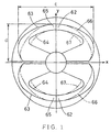
- FIG. 1 is a diagram of a deflection yoke of the present invention viewed from the screen side.
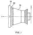
- FIG. 2 is a plan view of a deflection yoke of FIG. 1.
- FIG. 3 is a diagram illustrating the magnetic field oriented to the tube axis generated at the vicinity of corner portions of the screen side flange portion of the horizontal deflection coil and the Lorentz's force applied on the electron beam when the electron beam is deflected on the screen corner portions of the color cathode ray tube of the present invention.
- FIG. 4 is a diagram illustrating a high order raster distortion at the screen corners.
- FIG. 5 is a graph illustrating the relationship between the ratio of the maximum width and the maximum height of the screen side flange portion of the saddle shaped horizontal deflection coil r and the amount of a high order raster distortion c.
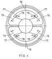
- FIG. 6 is a diagram illustrating the magnetic field oriented to the tube axis generated at the vicinity of corner portions of the screen side flange portion of the horizontal deflection coil and the Lorentz's force applied on the electron beam when the electron beam is deflected on the screen corner portions of the color cathode ray tube of the present invention.
- FIG. 7 is a plan view of a color cathode ray tube of the present invention.
- the magnetic field at the screen side of a deflection yoke is much more sensitive than the magnetic field at the electron gun side with respect to controlling the raster distortion. Therefore, methods such as controlling the raster distortion in the magnetic field generated by the screen side flange portion of the saddle shaped coil are highly effective.
- the magnetic field to the tube axis direction 78 is generated in the vicinity of the corner portions 77 of the screen side flange portion 76 of the saddle shaped horizontal deflection coil to apply the Lorentz's force 79 to the electron beam.
- the embodiments described in detail in the following Example 8 and the Example 9 are achieved with paying attention to the magnetic field to the tube axis direction 78 generated in the vicinity of the corner portions 77 of the screen side flange portion 76.
- the strength of the magnetic field to the tube axis direction 78 is intensified to reduce the high order raster distortion at the screen corners.
- FIG. 1 is a diagram illustrating an Example of the deflection yoke of the present invention viewed from the screen side and FIG. 2 is a plan view of the deflection yoke of FIG. 1.
- the deflection yoke comprises the saddle shaped wound horizontal deflection coil 68, the saddle shaped vertical deflection coil 69 located outside the horizontal deflection coil 68, and the ferrite core 70 located outside the vertical deflection coil 69.
- the shape of the contour of the screen side flange portion 65 of conventional horizontal deflection coils is described by the chain double-dashed lines 66, 67 in FIG. 1.
- the value of the above mentioned r in this case is usually 2.0.
- the contour 66, 67 of the screen side flange portion 65 of conventional horizontal deflection coils is formed to conform to the shape of the opposing glass funnel portion of the cathode ray tube, it becomes circular in shape.
- the contour 66, 67 of the screen side flange portion 65 of the horizontal deflection coil is formed to conform to the surface of the glass funnel portion of the cathode ray tube in order to minimize the energy loss by placing the screen side flange portion 65 of the horizontal deflection coil close to the electron beam.
- the magnetic field to the tube axis direction 72 is generated in the vicinity of the corner portions 74 of the screen side flange portion 62 of the horizontal deflection coil 68 to apply the Lorentz's force to the electron beam.
- the contour 66, 67 of the screen side flange portion 65 of a horizontal deflection coil has a circular shape like conventional arts, since the screen side flange portion 65 is placed closer to the electron beam, the strength of the magnetic field applied to the electron beam 72 becomes very strong.
- the value of r is 2.2 or more, since the amount of the high order raster distortion e at screen corner portions becomes 0.3 mm or less (see FIG. 5), and there would be no practical problems.
- the amount of r is greater than 3.5, a high order raster distortion is generated in the direction opposite to that of FIG. 26, which is not preferable.
- the present invention is not limited to the embodiment.
- FIG. 7 is a plan view illustrating an Example of the color cathode ray tube of the present invention.
- the color cathode ray tube main body 80 comprises the glass panel portion 81, and glass funnel portion 33 located to the rear part of the glass panel portion 81.
- An electron gun (not shown in FIG. 7) is provided behind the glass funnel portion 33.
- the deflection yoke comprising the saddle shaped horizontal deflection coil 68, the saddle shaped vertical deflection coil 69 located outside the horizontal deflection coil 68 and the ferrite core 70 located outside the vertical deflection coil 69, is located in the rear periphery of the glass funnel portion 33.
- the deflection yoke with the structure shown in the Example is used in the color cathode ray tube of this Example (see FIG. 1, FIG. 2).
- the screen side magnetic field of a deflection yoke is much more sensitive than the electron gun side magnetic field with respect to controlling a raster distortion. Therefore, a method of controlling a raster distortion by the magnetic field generated by the screen side flange portion of a saddle shaped coil is highly effective.
- the magnetic field to the tube axis direction 78 is generated in the vicinity of the corner portions 77 of the screen side flange portion 76 of the saddle shaped horizontal deflection coil to apply the Lorentz's force 79 to the electron beam.
- the embodiments described in detail in the following Example 10 and the Example 11 are achieved with paying attention to the magnetic field to the tube axis direction 78 generated in the vicinity of the corner portions 77 of the screen side flange portion 76.
- the strength of the magnetic field to the tube axis direction 78 is weakened to reduce the high order raster distortion at the screen surface.
Landscapes
- Video Image Reproduction Devices For Color Tv Systems (AREA)
- Vessels, Lead-In Wires, Accessory Apparatuses For Cathode-Ray Tubes (AREA)
Claims (2)
- Ablenkjoch mit einer sattelförmigen Horizontalablenkspule (68 , einer sattelförmigen Vertikalablenkspule (69), die sich außerhalb der sattelförmigen Horizontalablenkspule (68) befindet, und einem Kern (70), der sich außerhalb der sattelförmigen Vertikalablenkspule (69) befindet, wobei der bildschirmseitige Flanschabschnitt (62) der sattelförmigen Horizontalablenkspule (68) oder der sattelförmigen Vertikalablenkspule (69) eine Kontur einer sanft gekrümmten Linie aufweist und wobei das Verhältnis r = c / d des Flanschabschnitts (62) in dem Bereich von 2,2 bis 3,5 liegt, wobei c die Maximalbreite und d die Maximalhöhe ist.
- Farbkathodenstrahlröhre mit einem Farbkathodenstrahlröhren-Hauptkörper (80), der einen Glasplattenabschnitt (81) und einen Glastrichterabschnitt (33), der mit dem hinteren Teil des Glasplattenabschnitts (81) verbunden ist, aufweist, und dem Ablenkjoch nach Anspruch 1, das eine sich am hinteren Teil des Farbkathodenstrahlröhren-Hauptkörpers (80) befindende Elektronenkanone aufweist, wobei sich die sattelförmige Horizontalablenkspule (68) in der hinteren Umgebung des Farbkathodenstrahlröhren-Hauptkörpers (80) befindet.
Applications Claiming Priority (16)
| Application Number | Priority Date | Filing Date | Title |
|---|---|---|---|
| JP203903/94 | 1994-08-29 | ||
| JP6203903A JP3048503B2 (ja) | 1994-08-29 | 1994-08-29 | 偏向ヨーク及びこの偏向ヨークを装着したカラー陰極線管 |
| JP20390294A JP2969049B2 (ja) | 1994-08-29 | 1994-08-29 | 偏向ヨーク及びこの偏向ヨークを装着したカラー陰極線管 |
| JP203902/94 | 1994-08-29 | ||
| JP20390294 | 1994-08-29 | ||
| JP20390394 | 1994-08-29 | ||
| JP06206530A JP3075674B2 (ja) | 1994-08-31 | 1994-08-31 | 偏向ヨーク及びこの偏向ヨークを装着したカラー陰極線管 |
| JP206529/94 | 1994-08-31 | ||
| JP206531/94 | 1994-08-31 | ||
| JP20653194 | 1994-08-31 | ||
| JP6206529A JPH0869764A (ja) | 1994-08-31 | 1994-08-31 | 偏向ヨーク及びこの偏向ヨークを装着したカラー陰極線管 |
| JP20653094 | 1994-08-31 | ||
| JP206530/94 | 1994-08-31 | ||
| JP1994206531A JP3192326B6 (ja) | 1994-08-31 | 偏向ヨーク及びこの偏向ヨークを装着したカラー陰極線管 | |
| JP20652994 | 1994-08-31 | ||
| EP95113535A EP0700067B1 (de) | 1994-08-29 | 1995-08-29 | Ablenkjoch und Ablenkjoch enthaltende Farbkathodenstrahlröhre |
Related Parent Applications (2)
| Application Number | Title | Priority Date | Filing Date |
|---|---|---|---|
| EP95113535A Division EP0700067B1 (de) | 1994-08-29 | 1995-08-29 | Ablenkjoch und Ablenkjoch enthaltende Farbkathodenstrahlröhre |
| EP95113535.9 Division | 1995-08-29 |
Publications (2)
| Publication Number | Publication Date |
|---|---|
| EP0788134A1 EP0788134A1 (de) | 1997-08-06 |
| EP0788134B1 true EP0788134B1 (de) | 2000-12-27 |
Family
ID=27529337
Family Applications (4)
| Application Number | Title | Priority Date | Filing Date |
|---|---|---|---|
| EP97106574A Expired - Lifetime EP0790632B1 (de) | 1994-08-29 | 1995-08-29 | Ablenkjoch und das Ablenkjoch enthaltende Farbkathodenstrahlröhre |
| EP95113535A Expired - Lifetime EP0700067B1 (de) | 1994-08-29 | 1995-08-29 | Ablenkjoch und Ablenkjoch enthaltende Farbkathodenstrahlröhre |
| EP97106578A Expired - Lifetime EP0788135B1 (de) | 1994-08-29 | 1995-08-29 | Ablenkjoch und das Ablenkjoch enthaltende Farbkathodenstrahlröhre |
| EP97106570A Expired - Lifetime EP0788134B1 (de) | 1994-08-29 | 1995-08-29 | Ablenkjoch und Ablenkjoch enthaltende Farbkathodenstrahlröhre |
Family Applications Before (3)
| Application Number | Title | Priority Date | Filing Date |
|---|---|---|---|
| EP97106574A Expired - Lifetime EP0790632B1 (de) | 1994-08-29 | 1995-08-29 | Ablenkjoch und das Ablenkjoch enthaltende Farbkathodenstrahlröhre |
| EP95113535A Expired - Lifetime EP0700067B1 (de) | 1994-08-29 | 1995-08-29 | Ablenkjoch und Ablenkjoch enthaltende Farbkathodenstrahlröhre |
| EP97106578A Expired - Lifetime EP0788135B1 (de) | 1994-08-29 | 1995-08-29 | Ablenkjoch und das Ablenkjoch enthaltende Farbkathodenstrahlröhre |
Country Status (6)
| Country | Link |
|---|---|
| US (3) | US5859495A (de) |
| EP (4) | EP0790632B1 (de) |
| KR (1) | KR0162918B1 (de) |
| CN (2) | CN1118851C (de) |
| CA (1) | CA2157104C (de) |
| DE (4) | DE69520590T2 (de) |
Families Citing this family (11)
| Publication number | Priority date | Publication date | Assignee | Title |
|---|---|---|---|---|
| FR2751786B1 (fr) * | 1996-07-25 | 1998-10-16 | Thomson Tubes & Displays | Dispositif de fixation d'un deviateur sur le col d'un tube a rayons cathodiques |
| CN1083207C (zh) * | 1996-07-31 | 2002-04-17 | 松下电器产业株式会社 | 有鞍形偏转线圈的阴极射线管显示装置 |
| EP0823723B1 (de) * | 1996-08-07 | 2003-11-12 | Matsushita Electric Industrial Co., Ltd. | Kathodenstrahlröhrenanzeige mit Ablenkeinheit vom Satteltyp |
| US5668436A (en) * | 1996-08-07 | 1997-09-16 | Matsushita Electronics Corporation | Cathode ray tube displays having saddle-type deflecting coils |
| JP3543900B2 (ja) * | 1996-12-27 | 2004-07-21 | 松下電器産業株式会社 | 陰極線管装置 |
| KR100288807B1 (ko) * | 1997-07-29 | 2001-06-01 | 가나이 쓰도무 | 편향요크 및 이것을 사용한 음극선관장치와 디스플레이장치 |
| TW466531B (en) * | 1998-12-07 | 2001-12-01 | Koninkl Philips Electronics Nv | Saddle-shaped deflection coil and winding method |
| US20030062818A1 (en) * | 2001-10-01 | 2003-04-03 | Matsushita Electric Industrial Co., Ltd. | Cathode-ray tube device |
| JP2005158683A (ja) * | 2003-10-31 | 2005-06-16 | Victor Co Of Japan Ltd | 偏向ヨーク及びその製造方法 |
| CN112863861A (zh) * | 2021-01-09 | 2021-05-28 | 安徽新兆科技有限公司 | 一种用于电力设备的线圈绕线装置 |
| CN117731966B (zh) * | 2023-12-19 | 2024-10-08 | 中山大学 | 一种闪放治疗用嵌套马鞍形扫描磁铁 |
Family Cites Families (14)
| Publication number | Priority date | Publication date | Assignee | Title |
|---|---|---|---|---|
| US3027500A (en) * | 1959-07-20 | 1962-03-27 | Gen Electric | Width control |
| US3488541A (en) * | 1966-04-06 | 1970-01-06 | Rca Corp | Geodesic electromagnetic deflection yoke |
| US3895329A (en) * | 1973-12-19 | 1975-07-15 | Gen Electric | Toroidal-like saddle yoke |
| US4143346A (en) * | 1977-07-26 | 1979-03-06 | Zenith Radio Corporation | Self converging, north/south pin cushion corrected hybrid yoke |
| JPS5434712A (en) | 1977-08-24 | 1979-03-14 | Hitachi Ltd | Deflection yoke |
| NL170573C (nl) * | 1978-01-18 | 1982-11-16 | Philips Nv | Afbuiginrichting voor een kleurentelevisiebeeldbuis. |
| GB2162364A (en) * | 1984-07-27 | 1986-01-29 | Philips Electronic Associated | Saddle coils for electromagnetic deflection units |
| NL8600355A (nl) * | 1986-02-13 | 1987-09-01 | Philips Nv | Inrichting voor het weergeven van televisiebeelden en afbuigeenheid daarvoor. |
| JPH02216738A (ja) * | 1989-02-16 | 1990-08-29 | Matsushita Electric Ind Co Ltd | 偏向ヨーク |
| DE69024789T2 (de) * | 1990-05-11 | 1996-09-19 | Thomson Tubes & Displays S.A., Courbevoie | Selbstkonvergierendes Farbbildröhrensystem mit grossem Bildschirm |
| ATE133514T1 (de) * | 1990-05-18 | 1996-02-15 | Thomson Tubes & Displays | Ablenkjoch mit überlappenden ablenkspulen |
| US5077533A (en) * | 1990-09-28 | 1991-12-31 | Syntronic Instruments, Inc. | Cathode ray tube deflection yoke arrangement |
| JP3109744B2 (ja) * | 1990-12-07 | 2000-11-20 | 株式会社東芝 | 陰極線管装置 |
| US5233582A (en) * | 1991-02-19 | 1993-08-03 | Pioneer Electronic Corporation | Optical waveguide recording medium playing apparatus |
-
1995
- 1995-08-28 CA CA002157104A patent/CA2157104C/en not_active Expired - Fee Related
- 1995-08-29 EP EP97106574A patent/EP0790632B1/de not_active Expired - Lifetime
- 1995-08-29 DE DE69520590T patent/DE69520590T2/de not_active Expired - Fee Related
- 1995-08-29 DE DE69513906T patent/DE69513906T2/de not_active Expired - Fee Related
- 1995-08-29 KR KR1019950027050A patent/KR0162918B1/ko not_active Expired - Fee Related
- 1995-08-29 CN CN95116662A patent/CN1118851C/zh not_active Expired - Fee Related
- 1995-08-29 DE DE69525464T patent/DE69525464T2/de not_active Expired - Fee Related
- 1995-08-29 EP EP95113535A patent/EP0700067B1/de not_active Expired - Lifetime
- 1995-08-29 EP EP97106578A patent/EP0788135B1/de not_active Expired - Lifetime
- 1995-08-29 EP EP97106570A patent/EP0788134B1/de not_active Expired - Lifetime
- 1995-08-29 DE DE69519743T patent/DE69519743T2/de not_active Expired - Fee Related
-
1997
- 1997-06-27 US US08/884,321 patent/US5859495A/en not_active Expired - Fee Related
-
1998
- 1998-02-23 US US09/028,224 patent/US5986397A/en not_active Expired - Fee Related
- 1998-02-23 US US09/027,543 patent/US5982087A/en not_active Expired - Fee Related
-
2001
- 2001-06-18 CN CNB011219858A patent/CN1150591C/zh not_active Expired - Fee Related
Also Published As
| Publication number | Publication date |
|---|---|
| DE69525464D1 (de) | 2002-03-21 |
| US5982087A (en) | 1999-11-09 |
| DE69513906T2 (de) | 2000-05-04 |
| CN1150591C (zh) | 2004-05-19 |
| CN1125895A (zh) | 1996-07-03 |
| EP0788134A1 (de) | 1997-08-06 |
| US5986397A (en) | 1999-11-16 |
| KR0162918B1 (ko) | 1998-12-01 |
| CN1337731A (zh) | 2002-02-27 |
| DE69520590D1 (de) | 2001-05-10 |
| KR960008947A (ko) | 1996-03-22 |
| CA2157104A1 (en) | 1996-03-01 |
| DE69520590T2 (de) | 2001-08-30 |
| DE69519743D1 (de) | 2001-02-01 |
| DE69513906D1 (de) | 2000-01-20 |
| US5859495A (en) | 1999-01-12 |
| EP0700067B1 (de) | 1999-12-15 |
| EP0790632A1 (de) | 1997-08-20 |
| EP0700067A1 (de) | 1996-03-06 |
| EP0788135B1 (de) | 2002-02-13 |
| CN1118851C (zh) | 2003-08-20 |
| DE69525464T2 (de) | 2002-07-11 |
| CA2157104C (en) | 2002-03-12 |
| DE69519743T2 (de) | 2001-06-21 |
| EP0788135A1 (de) | 1997-08-06 |
| EP0790632B1 (de) | 2001-04-04 |
Similar Documents
| Publication | Publication Date | Title |
|---|---|---|
| EP0788134B1 (de) | Ablenkjoch und Ablenkjoch enthaltende Farbkathodenstrahlröhre | |
| EP0613168B1 (de) | Ablenkjoch mit einem Magnetenpaar in der Nähe seiner Nebenachse | |
| JPH05217518A (ja) | セミサドル形のフィールド偏向コイルを有する偏向ユニットをそなえた表示管 | |
| JP3543900B2 (ja) | 陰極線管装置 | |
| EP0936657B1 (de) | Ablenkjoch und mit dem Ablenkjoch versehene Farbkathodenstrahlröhre | |
| US5306982A (en) | Field harmonic enhancer in a deflection yoke | |
| US6008574A (en) | Deflection yoke providing improved image quality | |
| CA2360570C (en) | Deflection yoke and color cathode ray tube comprising the deflection yoke | |
| US5942846A (en) | Deflection yoke with horizontal deflection coil | |
| JP3075674B2 (ja) | 偏向ヨーク及びこの偏向ヨークを装着したカラー陰極線管 | |
| JP3048503B2 (ja) | 偏向ヨーク及びこの偏向ヨークを装着したカラー陰極線管 | |
| KR100541588B1 (ko) | 기하학적 형상과 컨버전스 모두가 개선된 음극선관용 편향 요크 | |
| JP3192326B6 (ja) | 偏向ヨーク及びこの偏向ヨークを装着したカラー陰極線管 | |
| JP3192326B2 (ja) | 偏向ヨーク及びこの偏向ヨークを装着したカラー陰極線管 | |
| JPH0869762A (ja) | 偏向ヨーク及びこの偏向ヨークを装着したカラー陰極線管 | |
| KR100334670B1 (ko) | 편향요크의그린빔드롭현상방지장치 | |
| JP2001118528A (ja) | 陰極線管用の電磁偏向装置 | |
| US20040183426A1 (en) | Deflection coil for deflection yoke | |
| JPH0869764A (ja) | 偏向ヨーク及びこの偏向ヨークを装着したカラー陰極線管 | |
| KR20030088377A (ko) | 음극선관, 음극선관장치, 화상표시장치 및 코일유니트 | |
| HK1004581B (en) | Deflection yoke with a pair of magnets near its minor axis | |
| HK1004581A1 (en) | Deflection yoke with a pair of magnets near its minor axis | |
| JPH08126019A (ja) | 偏向ヨーク | |
| JPH0389437A (ja) | インライン形カラー受像管用偏向装置 | |
| MXPA99005755A (es) | Un yugo de desviacion con correccion de distorsion de geometria |
Legal Events
| Date | Code | Title | Description |
|---|---|---|---|
| PUAI | Public reference made under article 153(3) epc to a published international application that has entered the european phase |
Free format text: ORIGINAL CODE: 0009012 |
|
| AC | Divisional application: reference to earlier application |
Ref document number: 700067 Country of ref document: EP |
|
| AK | Designated contracting states |
Kind code of ref document: A1 Designated state(s): DE FR GB IT NL SE |
|
| 17P | Request for examination filed |
Effective date: 19971007 |
|
| 17Q | First examination report despatched |
Effective date: 19981229 |
|
| GRAG | Despatch of communication of intention to grant |
Free format text: ORIGINAL CODE: EPIDOS AGRA |
|
| RIN1 | Information on inventor provided before grant (corrected) |
Inventor name: SHIMADA, KOJI Inventor name: HONDA, MASANOBU |
|
| GRAG | Despatch of communication of intention to grant |
Free format text: ORIGINAL CODE: EPIDOS AGRA |
|
| GRAG | Despatch of communication of intention to grant |
Free format text: ORIGINAL CODE: EPIDOS AGRA |
|
| GRAH | Despatch of communication of intention to grant a patent |
Free format text: ORIGINAL CODE: EPIDOS IGRA |
|
| GRAH | Despatch of communication of intention to grant a patent |
Free format text: ORIGINAL CODE: EPIDOS IGRA |
|
| GRAA | (expected) grant |
Free format text: ORIGINAL CODE: 0009210 |
|
| AC | Divisional application: reference to earlier application |
Ref document number: 700067 Country of ref document: EP |
|
| AK | Designated contracting states |
Kind code of ref document: B1 Designated state(s): DE FR GB IT NL SE |
|
| ITF | It: translation for a ep patent filed | ||
| REF | Corresponds to: |
Ref document number: 69519743 Country of ref document: DE Date of ref document: 20010201 |
|
| ET | Fr: translation filed | ||
| RAP2 | Party data changed (patent owner data changed or rights of a patent transferred) |
Owner name: MATSUSHITA ELECTRIC INDUSTRIAL CO., LTD. |
|
| PLBE | No opposition filed within time limit |
Free format text: ORIGINAL CODE: 0009261 |
|
| STAA | Information on the status of an ep patent application or granted ep patent |
Free format text: STATUS: NO OPPOSITION FILED WITHIN TIME LIMIT |
|
| NLT2 | Nl: modifications (of names), taken from the european patent patent bulletin |
Owner name: MATSUSHITA ELECTRIC INDUSTRIAL CO., LTD. |
|
| 26N | No opposition filed | ||
| REG | Reference to a national code |
Ref country code: GB Ref legal event code: IF02 |
|
| NLS | Nl: assignments of ep-patents |
Owner name: MATSUSHITA ELECTRIC INDUSTRIAL CO., LTD. |
|
| REG | Reference to a national code |
Ref country code: FR Ref legal event code: TP |
|
| NLS | Nl: assignments of ep-patents |
Owner name: MATSUSHITA ELECTRIC INDUSTRIAL CO., LTD. |
|
| PGFP | Annual fee paid to national office [announced via postgrant information from national office to epo] |
Ref country code: SE Payment date: 20060804 Year of fee payment: 12 |
|
| EUG | Se: european patent has lapsed | ||
| PG25 | Lapsed in a contracting state [announced via postgrant information from national office to epo] |
Ref country code: SE Free format text: LAPSE BECAUSE OF NON-PAYMENT OF DUE FEES Effective date: 20070830 |
|
| PGFP | Annual fee paid to national office [announced via postgrant information from national office to epo] |
Ref country code: NL Payment date: 20080815 Year of fee payment: 14 Ref country code: DE Payment date: 20080912 Year of fee payment: 14 |
|
| PGFP | Annual fee paid to national office [announced via postgrant information from national office to epo] |
Ref country code: IT Payment date: 20080827 Year of fee payment: 14 Ref country code: FR Payment date: 20080818 Year of fee payment: 14 |
|
| PGFP | Annual fee paid to national office [announced via postgrant information from national office to epo] |
Ref country code: GB Payment date: 20080903 Year of fee payment: 14 |
|
| REG | Reference to a national code |
Ref country code: NL Ref legal event code: V1 Effective date: 20100301 |
|
| GBPC | Gb: european patent ceased through non-payment of renewal fee |
Effective date: 20090829 |
|
| REG | Reference to a national code |
Ref country code: FR Ref legal event code: ST Effective date: 20100430 |
|
| PG25 | Lapsed in a contracting state [announced via postgrant information from national office to epo] |
Ref country code: NL Free format text: LAPSE BECAUSE OF NON-PAYMENT OF DUE FEES Effective date: 20100301 Ref country code: FR Free format text: LAPSE BECAUSE OF NON-PAYMENT OF DUE FEES Effective date: 20090831 Ref country code: DE Free format text: LAPSE BECAUSE OF NON-PAYMENT OF DUE FEES Effective date: 20100302 |
|
| PG25 | Lapsed in a contracting state [announced via postgrant information from national office to epo] |
Ref country code: GB Free format text: LAPSE BECAUSE OF NON-PAYMENT OF DUE FEES Effective date: 20090829 |
|
| PG25 | Lapsed in a contracting state [announced via postgrant information from national office to epo] |
Ref country code: IT Free format text: LAPSE BECAUSE OF NON-PAYMENT OF DUE FEES Effective date: 20090829 |