EP0788643B1 - Systeme de detection d'intrusion - Google Patents
Systeme de detection d'intrusion Download PDFInfo
- Publication number
- EP0788643B1 EP0788643B1 EP93918847A EP93918847A EP0788643B1 EP 0788643 B1 EP0788643 B1 EP 0788643B1 EP 93918847 A EP93918847 A EP 93918847A EP 93918847 A EP93918847 A EP 93918847A EP 0788643 B1 EP0788643 B1 EP 0788643B1
- Authority
- EP
- European Patent Office
- Prior art keywords
- line
- signal
- receiver
- perturbation
- signals
- Prior art date
- Legal status (The legal status is an assumption and is not a legal conclusion. Google has not performed a legal analysis and makes no representation as to the accuracy of the status listed.)
- Expired - Lifetime
Links
Images

Classifications
-
- G—PHYSICS
- G08—SIGNALLING
- G08B—SIGNALLING SYSTEMS, e.g. PERSONAL CALLING SYSTEMS; ORDER TELEGRAPHS; ALARM SYSTEMS
- G08B13/00—Burglar, theft or intruder alarms
- G08B13/22—Electrical actuation
- G08B13/24—Electrical actuation by interference with electromagnetic field distribution
- G08B13/2491—Intrusion detection systems, i.e. where the body of an intruder causes the interference with the electromagnetic field
- G08B13/2497—Intrusion detection systems, i.e. where the body of an intruder causes the interference with the electromagnetic field using transmission lines, e.g. cable
Definitions
- the invention relates to intrusion detection systems and in particular to intrusion detection systems which comprise an open or "leaky" transmission line, for example a leaky cable, for receiving a radio frequency signal and receiver means attached to the open transmission line for processing the received radio frequency signal to detect perturbations caused by an intruder in proximity to the open transmission line.
- an open or "leaky” transmission line for example a leaky cable
- US patent number 4,224,607 (Poirier) issued September 23, 1980, discloses an intrusion detection system comprising a length of leaky transmission line encompassing the region to be protected, a receiving antenna within the region, an R.F. transmitter and a remotely located receiver and detector. Effects of attenuation along the line are reduced by switching the transmitter periodically to opposite ends of the leaky cable. Nevertheless, this is only a partial solution. The sensitivity is still greater at the ends of the cable than at the middle of the cable so the system would not necessarily provide detection anywhere along the cable while not being susceptible to false alarms from the more sensitive start end of the cable. Where a longer line is needed to protect a greater area, especially if an inexpensive cable with a relatively high attenuation is used, the variation in sensitivity would be even greater.
- the present invention seeks to eliminate, or at least mitigate, the disadvantages of the known intrusion detection systems and to provide an improved leaky cable intrusion detection system.
- an intrusion detection system comprises an open transmission line; receiver means connected to both ends of the transmission line; means for providing at the receiver means a reference local oscillator signal (LO) and a reference intermediate frequency signal (IF REF ); the receiver means being responsive to the reference local oscillator signal and the reference intermediate frequency signal to extract from a first radio frequency signal (RF S ) received at one end (S) of the line a first baseband signal (M S ) comprising a perturbation signal (R S ) and to extract from a second radio frequency signal (RF T ) received at the other end (T) of the line a second baseband signal (M T ) comprising a second perturbation signal (R T ), the first and second perturbation signals being produced contemporaneously by an intruder in proximity to the line, characterized by processor means for processing the first baseband signal and second baseband signal to provide a combined response signal in dependence upon both the first perturbation signal and the second perturbation signal and in inverse proportion to attenuation of
- the system may, advantageously, be capable of receiving, selectively, a plurality of transmissions at different frequencies, perhaps different commercial stations.
- the processor means may conveniently select the different frequencies by varying the reference local oscillator signal frequency.
- the processor means may also be capable of adjusting receiver gain to compensate for different signal strengths of the different transmissions. The particular frequencies selected, and the corresponding gain factors, may be determined during a preliminary calibration of the installed system.
- the system is also desirable for the system to be capable of determining the position of the intruder along the cable.
- the processor means also derives the distance to the intruder from the start end of the line in dependence upon the first perturbation signal and the corresponding perturbation signal, preferably in proportion to the difference between logarithmic values derived from them.
- the receiver means may comprise first receiver means and second receiver means connected to opposite ends, respectively, of the transmission line, both tuned to the frequency of the radio frequency signal and coupled for synchronous detection of the signal.
- the first and second receiver means both use the reference local oscillator signal to detect the radio frequency signal at each end of the line and produce respective intermediate frequency signals.
- communication of signals and power between the first and second receiver means may take place via the line itself.
- the means for providing the reference local oscillator signal and the reference intermediate frequency signal comprises a third receiver which receives the transmitted radio frequency signal directly from a remote transmitter, for example a commercial radio or television station or a navigation signal transmitter, and derives the reference signals from the direct radio frequency signal. Where two receiver means are involved, the reference intermediate frequency signal will synchronize them to the transmitted radio frequency signal and to each other.
- a remote transmitter for example a commercial radio or television station or a navigation signal transmitter
- the first and second receiver means each comprise a line receiver and a demodulator.
- Each line receiver is connected to the transmission line and uses the reference local oscillator signal to derive its intermediate frequency signal from the line signal.
- the demodulator will then use the reference intermediate signal to demodulate the intermediate frequency signal from the associated line receiver to provide the perturbation signals representing the perturbation created by the intruder.
- the perturbation signals from the first and second receiver means are processed by the processing means, as previously mentioned, to detect the presence of an intruder or/and the location of the intruder along the open transmission line.
- each demodulator provides in-phase and quadrature signal components of the perturbation signal at its end of the line and the processor combines the magnitude and phase information of each of the perturbation signals to detect the presence of an intruder.
- One means of combining the signals from the two ends of the line is to add the logarithmic values of the sum of the squares of the in-phase and quadrature component signals.
- the system indicates the presence of the intruder when the sum of the two logarithms exceeds a predefined threshold.
- the processor may also use the difference between the two magnitude logarithms to determine the distance of the intruder from the start of the line.
- the use of logarithmic values is a very practical way to combine the signals from both ends of the line.
- performance can be enhanced by using linear summation of magnitudes of the signals from the two ends of the line and comparing the sum with a variable threshold.
- the perturbation signals from opposite ends of the line are added and compared with a threshold which varies according to the distance along the line, especially according to the ratio between the perturbation signal magnitudes at various discrete positions along it.
- the ratio might be 2:1, increasing in steps to, say, 4:1 at the ends.
- an intruder detection system comprises an open or "leaky” transmission line 10, conveniently an apertured coaxial cable of the kind usually called a “leaky cable”.
- the line 10 is connected to receiver means comprising two line receivers 12S and 12T coupled to coherent demodulators 14S and 14T, respectively, and a reference receiver 16.
- the receiver means are controlled by, and supply signals to, a microcontroller or digital signal processor 18.
- the reference receiver 16 has an antenna 20 for direct reception of a radio frequency signal transmitted by a remote transmitter 22 of a commercial radio or television station.
- the reference receiver 16 derives from the received radio frequency signal a reference local oscillator signal LO, which it supplies on line 24 to both of the line receivers 12S and 12T, and a reference intermediate frequency signal IF REF which it supplies on line 26 to the demodulators 14S and 14T.
- the line receivers 12S and 12T are connected to the start and the termination, respectively, of the open transmission line 10 and will receive the radio frequency signal from transmitter 22 via the line 10.
- the open transmission line 10 receives only a very weak signal from the radio transmitter 22.
- the intruder 28 moves in proximity to the open transmission line 10
- a discontinuity is created in the characteristic impedance of the line 10 and the radio frequency signal striking the intruder 28 is introduced into the line 10, where it propagates both to the start and termination ends of the line 10.
- the line receivers 12S and 12T receive perturbed radio frequency signals RF S and RF T , respectively, which each comprise a component due to the perturbation signal coupled by the intruder 28 into the open transmission line 10.
- the modulation caused by a human intruder moving between 0.02 and 8 meters per second is between, approximately, 0.005 Hz. and 6 Hz.
- the reference intermediate frequency signal IF REF is not disturbed by the intruder 28, whereas the intermediate frequency signals IF S and IF T produced by the line receivers 12S and 12T are modulated by the intruder 28.
- the line receivers 12S and 12T by sharing the same local oscillator signal LO, are tuned precisely to the same station as reference receiver 16, so their intermediate frequency signals IF S and IF T contain the same broadcast frequency modulation but at the IF frequency. Because these intermediate frequency signals are coherent, the demodulation process effectively eliminates the broadcast modulation leaving only the modulation induced via the line 10.
- the intermediate frequency signal IF REF from the reference receiver 16 is mixed with the intermediate frequency signals IF S and IF T from the line receivers 12S and 12T in demodulators 14S and 14T, corresponding baseband signals M S and M T comprising amplitude and phase modulation due to the intruder 28, are detected.
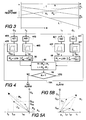
- Demodulator 14S is shown in detail in Figure 2; demodulator 14T being identical.
- the mixer 30 mixes the reference intermediate frequency signal IF REF with the intermediate frequency signal IF S from the line receiver 12S to extract the baseband signal M S . Since the output of mixer 30 includes all the usual mixing products, it is supplied to a low pass filter 32 which eliminates all of the upper cross products above about 3.75 Hz. leaving only the in-phase baseband component Is of baseband signal M S .
- the reference intermediate frequency signal IF REF is delayed by 90 degrees in a quadrature hybrid circuit 34 before being supplied to a second mixer 36 which mixes it with the intermediate frequency signal IF S .
- the output of mixer 36 is filtered by a second low pass filter 38 to remove frequencies above about 3.75 Hz., resulting in the quadrature baseband component Q S of baseband signal M S .
- demodulator 14S supplies the in-phase and quadrature components I S and Q S of the start-end baseband signal M S to the digital signal processor 18.
- the demodulator 14T having used the reference intermediate frequency signal IF REF and the intermediate frequency signal IF T from line receiver 12T to produce corresponding in-phase and quadrature components I T and Q T for the termination baseband signal M T , supplies the components I T and Q T to the digital signal processor 18.
- the digital signal processor 18 uses the in-phase and quadrature signals I S , Q S , I T and Q T from both demodulators 14S and 14T to compute a logarithmic value, as will be described in more detail later, and compares this logarithmic value with a reference or threshold, illustrated in Figure 3 by the dashed line T. If this combined logarithmic value exceeds the threshold T, the processor 18 generates an alarm indicating that an intruder 28 is within the detection zone somewhere along the open transmission line 10.
- the open transmission line 10 does not pick up any of the radio transmissions unless an intruder 28 is in proximity to the line.
- stationary objects and line imperfections scatter the transmissions and introduce "fixed clutter" signals into the open transmission line 10 along its length.
- slow environmental changes occur below the passband and higher frequency responses above the passband may be caused by flying birds, etc. Consequently, the processor 18 processes the baseband signals M S and M T in such a way that signals introduced into the line 10 at frequencies outside the range 0.005 Hz. to 6 Hz., mentioned above, will be excluded. Processing of the baseband signals by processor 18 is illustrated in Figure 4.
- the in-phase and quadrature components I S and Q S from demodulator 14S include clutter components I CS and I CT and intruder perturbation signal components I RS and Q RS , combining to give a magnitude of M S .
- the in-phase and quadrature response components I T and Q T of demodulator 14T include clutter components I CT and Q CT and intruder perturbation signal components I RT and Q RT combining to give a magnitude of M T .
- the processor 18 digitizes and filters the in-phase and quadrature components. Normal precautions need to be taken to digitize at a sufficient rate to eliminate aliasing and with a sufficient number of bits to provide adequate dynamic range to accommodate the expected range of modulation.
- the quadrature signal component Q S from low pass filter 38 in demodulator 14S ( Figure 2) is digitized by analogue-to-digital converter 40S and filtered by a band pass filter 42S, with a lower cutoff of about 0.005 Hz. and an upper cutoff of about 6 Hz, to derive the incremental intruder response vector component Q RS .
- the in-phase signal component Is from low pass filter 32 ( Figure 2) is digitized by analogue-to-digital converter 44S and filtered by band pass filter 46S to derive the incremental intruder response vector component I RS .
- the in-phase and quadrature signal components I T and Q T from the demodulator 14T are processed in like manner by analogue-to-digital converters 40T and 44T and band pass filters 42T and 46T to give corresponding incremental intruder response or perturbation signal components I RT and Q RT , respectively.
- the lower cutoff frequency of each of the band pass filters 42S, 42T, 46S, 46T is in the order of 0.005 Hz to pass the perturbation signal due to an intruder moving faster than 0.002 m/sec. while removing the environmental drift and fixed clutter information.
- the upper cutoff frequency of each of the bandpass filters 42S, 42T, 46S and 46T is in the order of 6 Hz. to pass the perturbation signal due to the intruder 28 moving slower than about 8 meters/second while removing all higher frequency noise.
- the processor 18 computes the value R S ' as the logarithm of the sum of the squares of the corresponding incremental responses I RS and Q RS , and, as indicated by function box 58, the response R T ' from incremental responses I RT and Q RT .
- the processor 18 computes the sum R and the difference L of the logarithmic responses R S ' and R T ' as indicated by box 60.
- the sum R is then compared to threshold T, as shown in decision box 62, to determine whether or not an intruder is present and, if so, generate an alarm signal.
- the difference L between the logarithmic responses is determined to indicate where the intruder is located along the length of the open transmission line 10 relative to the start of the line 10.
- the difference L between the logarithmic values R S ' and R T ' of the perturbation signals is linear and, as shown in Figure 3, decreases rapidly as the intruder moves along the length of the open transmission line 10.
- the magnitude of this difference L between the logarithmic values is directly proportional to the intruder's distance x from the start end of the open transmission line 10.
- the digital signal processor 18 is able to determine the intruder's location along the open transmission line 10.
- the system takes account of the attenuation of signals propagating along the length of the open transmission line 10 to locate the intruder 28. Attenuation causes signals propagating along transmission lines to decay exponentially with distance. Hence, a logarithmic function of the exponential attenuation with distance along the length of the line becomes linear.
- the ideal magnitude of the logarithmic perturbation signal for the start of the line due to an intruder 28 walking along the length of the open transmission line 10 is represented by the sloping line R S '.
- the slope of this line R S ' is determined by the attenuation of the open transmission line 10.
- the magnitude of the logarithmic perturbation signal for the termination end of the line is shown as sloping line R T '. It will be noted that, because line receivers 12S and 12T are at opposite ends of the open transmission line 10, the slopes of lines R S ' and R T ' are equal and opposite.
- the actual level of the threshold T will be determined by the processor 18 following an initial set-up phase.
- the processor 18 controls the tuning of the reference receiver 16 by means of the control signal Select f , and the associated gain settings for the demodulators 14S and 14T by means of the gain control signal ADJ. GAIN.
- the processor 18 controls the reference receiver 16 to scan the entire FM band so as to select the most desirable station frequency for use by the system.
- the processor 18 will generate a table of available stations and appropriate gain settings for the demodulators 14S and 14T to maintain the signal components I S ,Q S and I T ,Q T at a constant amplitude. The processor 18 is then able to select N frequencies for use by the detection system where N is the number of stations for which the system is designed. Once this initial set-up phase is completed the system is ready to be calibrated.
- the processor 18 determines the appropriate level for threshold T to provide the desired detection capability. With the system in calibration mode, a human, or a simulated human, crosses the line 10 at its centre. The processor 18 records the peak signal perturbation during this crossing as seen from each end of the line 10. (Where N transmission frequencies are used, it does so for the combination of the N frequencies). The processor 18 uses this peak response together with a sensitivity setting controlled by the user to select an appropriate threshold setting T.
- This calibration procedure takes into account the length of line 10, its attenuation and the nature of its installation; i.e suspended in air, laid on the ground or buried in the ground.
- the processor 18 adjusts the gain of the demodulators 14S and 14T by means of the variable amplifier 29 ( Figure 2) until they do.
- the intruder 28 scatters the plane waves produced by the FM radio transmitter 22.
- the scattered signal propagates away from the intruder 28 in all directions causing a portion of the signal to be coupled into the open transmission line 10 where it propagates to the start and termination ends.
- an increasing amount of the scattered energy is coupled into the line causing a phase and/or amplitude modulation of the signal received on the open transmission line 10.
- This causes the combined logarithmic values of magnitude R S ' plus R T ' to increase as the intruder 28 approaches the line 10.
- the combined response R exceeds the threshold T and the alarm is sounded.
- the appropriate selection of a threshold value T determines the width of the detection zone which surrounds the open transmission line.
- the threshold T is uniform along the length of the line 10, thereby eliminating the need for cable grading.
- the difference (R S ' - R T ') between the logarithmic values is equivalent to the ratio between the perturbation signal magnitudes (R S /R T )
- the determination of location does not depend upon the magnitude of the perturbation. In other words, the determination of location is not a function of the radial distance to the intruder from the line.
- the performance of the intrusion detection system in terms of Probability of Detection (Pd) and False Alarm Rate (FAR) is largely determined by the Signal to Noise Ratio (SNR) of the system and the processing bandwidth.
- SNR Signal to Noise Ratio
- the open transmission line 10 is much less efficient than the reference antenna 20 in receiving the radio transmission, the RF signal received by the reference receiver 16 is much stronger than the signal received by the line receivers 12S, 12T (20 to 30 dB stronger).
- the line receivers 12S and 12T have considerably more gain than the reference receiver 16 which means that the line receivers 12S and 12T are the primary source of noise, typically thermal noise at the receiver "front end".
- the system SNR can be improved by minimizing the bandwidth of the line receivers 12S and 12T.
- conventional commercial FM radio receivers utilize 180 KHz of occupied bandwidth in order to accommodate the monaural and stereo transmissions, a much narrower bandwidth will accommodate the 0.005 to 6 Hz. modulation caused by the intruder 28.
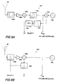
- FIGS 6A and 6B illustrate embodiments of reference receiver which will track the station modulation.
- the RF signal received on antenna 20 is passed through a broad bandpass filter 64A to eliminate signals from outside the FM band (88 to 108 MHz).
- the band-limited output of the filter 64A is amplified in a low noise amplifier 66A and passed to a mixer 68A which mixes it with the reference local oscillator signal LO produced by a Voltage Controlled Oscillator (VCO) 70A.
- VCO Voltage Controlled Oscillator
- the frequency of the VCO 70A is controlled by the SELECT f signal from processor 18.
- the SELECT f signal is actually a dc voltage that selects the desired station, much as in normal digitally controlled radios.
- the VCO 70A responds to the output of a Phase Locked Loop (PLL) filter 72A which receives its input from a phase comparator 74A.
- the reference intermediate frequency signal IF REF is extracted from the output of mixer 68A by filter 75A and compared by phase comparator 74A with a 10.7 MHz reference signal from an oscillator 76A.
- This PLL circuit tracks the modulation thereby effectively removing the modulation from the intermediate frequency and imposing the modulation on the reference local oscillator signal LO which is sent to the line receivers 12S and 12T.
- the RF signal received by antenna 20 is filtered by a tunable station pre-selection filter 64B.
- the output of filter 64B is passed through a pre-amplifier 66B to a mixer 68B where it is down-converted by a reference 10.7 MHz signal generated by reference oscillator 76B.
- the output of mixer 68B is filtered in a tunable bandpass filter 78B to produce the desired tracking reference local oscillator signal LO which is used to tune the line receivers 12S and 12T.
- the tuning of the pre-selection filter 64B and the bandpass filter 78B is controlled by the Select f signal from processor 18.
- the electromagnetic fields produced by the radio station at the open transmission line 10 include significant multipath components.
- a large building can reflect the broadcast plane waves over the open transmission line 10.
- embodiments of the invention might employ a plurality of different radio frequency signals as references so as to employ frequency and spatial diversity to minimize the effects of multipath components.
- there are a number of FM stations within the 88 to 108 MHz band which can be used in the present intrusion detection system.
- the transmit antennas are collocated for most of the stations.
- the line attenuation may be sufficiently small that the difference between the magnitudes of the perturbation signals seen at opposite ends of the line may be less than the variations in magnitude caused by noise. While this would inhibit the location ability of the system according to the present invention, since it is not usually necessary to know the location of an intruder on such a short length of sensor line, there is still considerable SNR benefit to be gained by adding the magnitudes of the perturbation signals from both ends of the line.
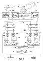
- FIG 7 which corresponds to Figure 4, illustrates an embodiment of the invention which deals with a more complex form of multipath distortion, i.e. transient multipath distortion, which is caused by reflections from moving objects such as vehicles on nearby roads.
- a moving vehicle 81 reflects a plane wave over the open transmission line 10. If the open transmission line 10 were perfectly uniform with no irregularities within its near field, the reflection from the moving vehicle 81 would not couple into the open transmission line 10 and would not cause a false alarm. In practice, however, the open transmission line 10 does have many small scattering objects randomly distributed along its length which couple energy into the open transmission line 10. Hence the moving vehicle 81 can cause false alarms by reflecting radio signals onto the fixed but distributed small objects within the field of the open transmission line 10.
- the processor 18B uses the intruder phase response information to reduce the number of false alarms due to transient multipath effects from moving distant vehicles.
- the open transmission line 10 operates in a quasi-TEM or surface wave mode
- the constant phase fronts close to the open transmission line 10 are virtually orthogonal to the line 10.
- the phase ⁇ RS of the intruder perturbation signal R S via the receiver 12S is the product of the transmission line phase factor, ⁇ , and the distance x S from the start of the line 10 to the intruder 28.
- the constant ⁇ is independent of the intruder location along the open transmission line 10.
- the signal injected by the distant moving vehicle 81 into the open transmission line 10 enters at random locations along the line and the phase angle ⁇ will be time-varying as the vehicle 81 moves.
- the processor 18B computes ⁇ RS , the phase of the incremental response vector at the start; ⁇ RT , the phase at the termination end; and sums them to give the phase angle ⁇ , as indicated by function boxes 80, 82 and 84, respectively.
- the processor 18B compares ⁇ with threshold values ⁇ 1 and ⁇ 2 to discriminate between perturbations due to intruders near the open transmission line 10 and perturbations due to large moving vehicles at a distance from the line 10.
- FIG. 1 requires three interconnecting cables; open transmission line 10, line 24 for the reference local oscillator signal, and line 26 for the reference intermediate frequency signal, as well as some means of connecting the demodulators 14S and 14T to the processor unit 18, and a power distribution network.
- This number of interconnecting cables could make the sensor procurement and installation costs prohibitive.
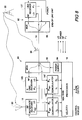
- Figure 8 illustrates an embodiment of the invention in which a control module 90 at the start end of the open transmission line 10 and an end-of-line or termination unit 92 at the other end are interconnected only by the open transmission line 10, the various signals being carried by the line 10 itself.
- the control module 90 comprises a reference receiver 16, line receiver 12S, demodulators 14S and 14T, and a processor unit 18, all similar to those described with reference to Figure 1.
- the control module 90 comprises a power supply 94 and a multiplexer unit 96.
- the end-of-line or termination unit 92 comprises line receiver 12T and a multiplexer unit 98.
- D.c. power from the power supply unit 94 and the local oscillator signal LO from the reference receiver 16 in the control module 90 are transmitted by way of the multiplexer units 96 and 98 to the line receiver 12T in the end-of-line unit 92.
- the intermediate frequency signal IF T from the line receiver 12T is returned to the demodulator 14T by way of the multiplexers 98 and 96.
- the open transmission line 10 carries the RF signal coupled into it along its length in both directions to the line receivers 12S and 12T, respectively, by way of multiplexers 98 and 96.
- the control module 90 may be designed to operate in an indoor environment and the end-of-line unit 92 designed to operate in either an indoor or an outdoor environment. Multiplexing the signals on the open transmission line 10 avoids the cost of additional cable and installation to incorporate the termination line receiver.
- end-of-line receiver provides an automatic form of self test for the open transmission line 10. This can easily be used to replace the normal tamper detection circuitry required in security sensors to detect when the cable is damaged.
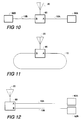
- the central control module 90 can be time-multiplexed between two open transmission lines 10A and 10B terminated by termination units 92A and 92B, respectively. This allows one to have two lengths of open transmission line 10A and 10B for one reference antenna 20, one reference receiver 16, one line receiver 12S, one pair of demodulators 14S and 14T and one processor unit 18.
- Figure 11 illustrates another of the many ways that systems with a common, time multiplexed control module 90 can be adapted to address specific applications.
- Figure 11 illustrates a closed loop system in which the end-of-line receivers 92 are eliminated by connecting the line 10 between the A and B ports of the control module 90.
- Appropriate changes in the processing software of processor 18 enable ports A and B to replace start S and termination T in the more general application. It should be noted that, in this embodiment of the invention, one does not need to communicate the signals over the open transmission line 10 since the control module 90 has access to both ends of the line 10.
- Figure 12 illustrates the two open transmission lines 10A and 10B installed parallel to each other. This approach enlarges the detection zone and allows one to combine the detection results to lower the false alarm rate or to provide the direction of crossing.
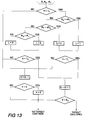
- the processor 18 may compare the average magnitude R to a threshold which is a function of the location of the intrusion along the length of the line 10. Where multiple frequencies are involved, the average magnitude R will be obtained by summing the start perturbation signals for all frequencies, summing the termination perturbation signals for all frequencies and taking the average.
- T 0 the threshold at the centre of the line 10
- l the distance from the centre of the line in meters
- ⁇ the attenuation of the cable in Nepers per meter.
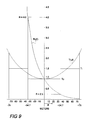
- Figure 9 illustrates the function T(l) to provide uniform detection for a line with 18dB of attenuation per meter.
- processor 18 might be further modified to make a stepwise approximation to the ideal threshold curve shown in Figure 9 as a function of simple binary ratios of R S /R T so as to avoid performing the division, the logarithm and the cosh function.
- the threshold is T 0 , the level set by the user during calibration, as mentioned previously.
- the operation of processor 18 to process the signals using a variable threshold is illustrated in Figure 13.
- the reference receiver antenna 20 should be located so as to obtain the strongest signal from the station transmitter free of time-varying multipath signals such as those which could be caused by nearby vehicular traffic.
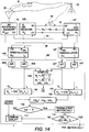
- FIG 14 Such additional processing is shown in Figure 14, in which components corresponding to those in Figure 7 have the same reference numeral.
- the processor means is identified by reference numeral 18C, the suffix "C" indicating that it differs from those of Figure 4 and Figure 7 in that it provides the additional processing.
- the components Q RS , I RS and Q RT , I RT are extracted by A/D converters 40, filtered using bandpass filters and processed as described before with reference to Figure 7.
- bandpass filtering and other processing are designated as "OTHER PROC'G" in Figure 14, only the additional processing being illustrated in detail.
- the baseband signal components Q S ,I S and Q T ,I T are processed as shown by function boxes 100 and 102 to determine the phase values ⁇ S and ⁇ T , respectively, of the baseband signal vectors M S and M T .
- the magnitudes of the baseband vectors M S and M T also are computed from their components Q S ,I S and Q T ,I T , respectively, as indicated by function box 104 .
- a truck 81 is shown moving so close to the reference antenna 20 that it interferes with the signal from transmitter 22.
- the motion of the truck 81 causes an identical change in the respective phases ⁇ S and ⁇ T of baseband signals M S and M T ( Figures 5A and 5B) but does not affect the amplitudes of baseband signals M S and M T because the reference receiver 16 "hard" limits to a fixed amplitude.
- the phase value changes ⁇ S and ⁇ T are subtracted to give the differential phase change ⁇ M between the baseband vectors. If there is a differential phase change, as detected by a positive result from comparison step 108, the possibility of the change being due to motion of, or at, the reference antenna 20 is determined by comparison step 110 which detects changes in amplitude of both M S and M T . If both amplitudes have not changed, the changes are attributed to motion at or of the reference antenna.
- comparison steps 108 and 110 both give negative outputs, i.e. the differential phase changed and one or both of the magnitudes M S and M T changed, a "possible target" is indicated, as determined by function box 112.
- a third approach is to "normalize" the response by rotating the vector plane by the phase response of one end (preferably the one with the larger clutter as this will give more accurate measurement of phase angle), or some function of the phase response of both ends, such as the average. This would eliminate response due to mutual phase shift, while still responding to amplitude response or non-correlated phase response, as would be generated by an intruder.
- the intrusion detection system according to the invention can be operated by providing a local CW transmission in the FM band. Naturally this will require radio regulatory approval.
- the reference antenna 20 Because of the popularity of FM radio, many types of low cost antennas are readily available as the reference antenna 20. Likewise the electronic circuitry required in the reference receiver 16 and the line receivers 12S, 12T may employ inexpensive sophisticated integrated circuits developed for the entertainment industry.
- the open transmission line 10 can be virtually any type of transmission line that supports an external electromagnetic field. Perhaps the simplest such transmission line is a wire suspended above ground to form an Image Line. Other suitable open transmission lines are Two Wire Lines, Strip Line and Surface Wave Lines. The key properties of such an open transmission line as it relates to the present invention are that it guides an electromagnetic field along its length at a known velocity of propagation with minimal radiation and with a field that decays with radial distance. The radial decay rate determines the size of the detection zone.
- Embodiments of the invention yield various advantages over known systems. For example, embodiments using only one cable involve reduced costs.
- the intrusion detection system may be passive which simplifies production and obviates the need for FCC approval or approval of other regulatory bodies.
- Embodiments which use a commercial FM radio signal may use parts which are relatively cheap because they are available for FM radio receivers.
- the use of multiple reference signal frequencies enhances signal to noise ratio and reduces multipath effects while increasing reliability.
- the radio station is a commercial FM radio station operating in the 88 to 108 MHz band of frequencies. Electromagnetic fields at these frequencies are ideal for detecting human intruders while rejecting small animals and birds because an adult human is between one quarter and one half wavelength tall causing it to have considerably larger radar cross section than a small animal which may only be one tenth of a wavelength tall.
- Commercial FM radio stations are also ideal because there are usually many such stations in urban areas where crime is prevalent and security is required and because they typically transmit twenty four hours a day.
- An advantage of embodiments of the present invention, which deploy a receiver at each end of the open transmission line, is that they provide substantially uniform sensitivity without the expense and inconvenience of cable grading.
- Embodiments of the invention which employ transmissions from two or more stations also give enhanced performance through the use of frequency diversity which, together with the spatial diversity arising from the use of receivers at each end of the line, significantly improves the sensor performance in terms of uniformity of detection along the line length as well as providing a higher probability of detection and lower false alarms ratio than conventional single frequency, single ended leaky cable sensors.
Landscapes
- Physics & Mathematics (AREA)
- Electromagnetism (AREA)
- General Physics & Mathematics (AREA)
- Burglar Alarm Systems (AREA)
- Geophysics And Detection Of Objects (AREA)
Claims (24)
- Système de détection d'intrusion, comprenant :une ligne de transmission ouverte (10) ; des moyens récepteurs (12S, 12T, 14S, 14T) connectés aux deux extrémités de la ligne de transmission ; des moyens (16) pour fournir aux moyens récepteurs un signal d'oscillateur local de référence (LO) et un signal de fréquence intermédiaire de référence (IFREF) ; les moyens récepteurs répondant au signal d'oscillateur local de référence et au signal de fréquence intermédiaire de référence pour extraire d'un premier signal de fréquence radioélectrique (RFS), reçu à une extremité (S) de la ligne, un premier signal en bande de base (MS) comprenant un premier signal de perturbation (RS), et pour extraire d'un deuxième signal de fréquence radioélectrique (RFT), reçu à l'autre extrémité (T) de la ligne, un deuxième signal en bande de base (MT) comprenant un deuxième signal de perturbation (RT), les premier et deuxième signaux de perturbation étant produits simultanément par un intrus a proximité de la ligne, caractérisé par des moyens de traitement pour traiter le premier signal en bande de base et le deuxième signal en bande de base afin de produire un signal de réponse combiné en fonction du premier signal de perturbation et du deuxième signal de perturbation, et en proportion inverse à l'atténuation des signaux de fréquence radioélectrique par la ligne, et pour déterminer la présence de l'intrus en fonction du signal de réponse combiné.
- Système de détection d'intrusion selon la revendication 1, caractérisé en ce que ledit premier signal en bande de base (MS) et ledit deuxième signal en bande de base (MT) comprennent, en plus des premier et deuxième signaux de perturbation (RS, RT), des première et deuxième composantes d'échos parasites (CS, CT) sortant respectivement d'une gamme de fréquences prédéterminée, et les moyens de traitement peuvent être commandés pour supprimer les première et deuxième composantes d'échos parasites (CS, CT) avant de combiner les premier et deuxième signaux de perturbation (RS, RT) pour produire ledit signal de réponse combiné.
- Système de détection d'intrusion selon la revendication 2, caractérisé en ce que la gamme de fréquences prédéterminée est comprise entre environ 0,005 Hertz et environ 6 Hertz.
- Système de détection d'intrusion selon la revendication 1, caractérisé en ce que les moyens de traitement (18) peuvent être commandés de façon à additionner des valeurs logarithmiques (RS', RT') dudit premier signal de perturbation et dudit deuxième signal de perturbation en produisant ledit signal de réponse combiné (R).
- Système de détection d'intrusion selon la revendication 1, caractérisé en ce que les moyens de traitement (18) peuvent être commandés de façon à calculer la différence (L) entre une valeur logarithmique (RS') du premier signal de perturbation et une valeur logarithmique (RT') du deuxième signal de perturbation, et pour déterminer la position de l'intrus en comparant la différence avec une référence dépendant de la longueur de la ligne.
- Système de détection d'intrusion selon la revendication 1, caractérisé en ce que les moyens récepteurs comprennent un premier récepteur de ligne (12T) connecté à ladite autre extrémité de la ligne (10), le premier récepteur de ligne répondant au signal d'oscillateur local de référence (LO) pour déduire du premier signal de fréquence radioélectrique (RFS) un premier signal de fréquence intermédiaire (IFS) comprenant des perturbations induites par l'intrus, le deuxième récepteur de ligne (12T) répondant à l'oscillateur local de référence (LO) pour déduire du deuxième signal de fréquence radioélectrique (RFT) un deuxième signal de fréquence intermédiaire (IFT) comprenant des perturbations induites par l'intrus correspondantes, un premier démodulateur (14S) répondant au premier signal de fréquence intermédiaire (IFS) et au signal de fréquence intermédiaire de référence (IFREF) pour déduire ledit premier signal en bande de base (MS), et un deuxième démodulateur (14T) répondant au deuxième signal de fréquence intermédiaire (IFT) et au signal de fréquence intermédiaire de référence (IFREF) pour déduire ledit deuxième signal en bande de base (MT).
- Système de détection d'intrusion selon la revendication 6, caractérisé en ce que les premiers moyens démodulateurs (14S) et les deuxièmes moyens démodulateurs (14T) déduisent respectivement le premier signal en bande de base (MS) et le deuxième signal en bande de base (MT), sous la forme de composantes en phase et en quadrature (IS, QS ; IT, QT), et les moyens de traitement (18) peuvent être commandés de façon à combiner l'addition des carrés des composantes en phase et en quadrature du premier signal en bande base et ceux du deuxième signal en bande de base.
- Système de détection d'intrusion selon la revendication 7, caractérisé en ce que les moyens de traitement (18) peuvent en outre être commandés de façon à supprimer les composantes d'échos parasites à l'extérieur d'une gamme de fréquences prédéterminées.
- Système de détection d'intrusion selon la revendication 8, caractérisé en ce que la gamme de fréquence part d'environ 0,005 Hertz.
- Système de détection d'intrusion selon la revendication 6, caractérisé en ce que les moyens (16) servant à produire un signal d'oscillateur local de référence, le premier récepteur de ligne (12S) et les moyens de traitement (18) sont situés au niveau de ladite extrémité de la ligne (10) et couplés à cette dernière, le deuxième récepteur de ligne (12T) est situé à ladite autre extrémité de la ligne (10), le signal oscillateur local de référence (LO) est envoyé au deuxième récepteur de ligne par l'intermédiaire de la ligne (10) et le deuxième signal de fréquence intermédiaire (IFT) provenant du deuxième récepteur de ligne (12T) est renvoyé au deuxième démodulateur (14T) par l'intermédiaire de la ligne (10).
- Système de détection d'intrusion selon la revendication 10, caractérisé en ce que des premiers moyens multiplexeurs (96) couplent le premier récepteur de ligne (12S), les moyens (16) pour produire le signal d'oscillateur local de référence (LO) et le signal de fréquence intermédiaire de référence (IFREF), les premiers moyens démodulateurs (14S) et les deuxièmes moyens démodulateurs (14T) à la première extrémité de la ligne (10), et des deuxièmes moyens multiplexeurs (98) couplent le deuxième récepteur de ligne (12T) à l'autre extrémité de la ligne, l'aménagement étant tel que le signal d'oscillateur local de référence (LO) et la fréquence intermédiaire de référence (IFREF) sont couplés au deuxième récepteur de ligne (12T) par l'intermédiaire des premiers et deuxièmes moyens multiplexeurs (96, 98) et de la ligne (10), et le deuxième signal de fréquence intermédiaire perturbé (IFT) est renvoyé du deuxième récepteur de ligne (12T) aux deuxièmes moyens démodulateurs (14T) par l'intermédiaire des premiers et deuxièmes moyens multiplexeurs (96, 98) et de la ligne (10).
- Système de détection d'intrusion selon la revendication 1, caractérisé en ce que les moyens de traitement (18) peuvent en outre être commandés de façon à déterminer les angles de phase respectifs (RS, RT) du premier signal de perturbation et du deuxième signal de perturbation et à déterminer qu'un intrus est présent lorsque la somme () des angles de phase est comprise dans la gamme prédéterminée (1-2).
- Système selon la revendication 1, caractérisé en ce que le premier signal de fréquence radioélectrique (RFS) et le deuxième signal de fréquence radioélectrique (RFT) résultent du couplage à la ligne de transmission ouverte d'un signal de fréquence radioélectrique rayonné, et les moyens (16) pour produire comprennent un récepteur de référence pour recevoir le signal de fréquence radioélectrique rayonné sans perturbations par l'intrus et générer à partir de ce dernier le signal d'oscillateur local de référence (LO) et le signal de fréquence intermédiaire de référence (IFREF).
- Système selon la revendication 1, caractérisé en ce que les moyens récepteurs (12S, 12T, 14S, 14T) peuvent être réglés pour recevoir de manière sélective une pluralité (N) de transmissions à des fréquences différentes (f) et les moyens de traitement (18) peuvent être commandés de façon à combiner une pluralité correspondante de premiers signaux de perturbation aux différentes fréquences pour ladite extrémité de la ligne et une pluralité correspondante de deuxièmes signaux de perturbation pour ladite autre extrémité de la ligne.
- Système selon la revendication 14, caractérisé en ce que les moyens de traitement (18) peuvent être commandés de façon à sélectionner une fréquence de transmission particulière et régler le gain desdits moyens récepteurs (12S, 12T, 14S, 14T) à une valeur correspondante pour ainsi compenser les forces différentes des signaux des différentes transmissions.
- Système selon la revendication 14, caractérisé en ce que les moyens de traitement (18) peuvent être commandés de façon à déduire la valeur combinée en additionnant la pluralité de premiers signaux de perturbation, en additionnant la pluralité de deuxièmes signaux de perturbation, en calculant la valeur logarithmique de chaque somme ainsi produite et en additionnant les valeurs logarithmiques pour donner ladite valeur combinée.
- Système selon la revendication 14, caractérisé en ce que les moyens de traitement (18) peuvent être commandés de façon à additionner la pluralité de premiers signaux de perturbation, additionner la pluralité de deuxièmes signaux de perturbation, et additionner la première somme et la deuxième somme, et calculer le logarithme du résultat sous la forme de ladite valeur combinée.
- Système selon la revendication 1, caractérisé en ce que les moyens de traitement (18) peuvent être commandés de façon à comparer le signal de réponse combiné à une valeur seuil qui varie selon la distance sur la longueur de la ligne.
- Système selon la revendication 18, caractérisé en ce que les moyens de traitement (18) peuvent être commandés de façon à faire varier la valeur seuil selon l'expression
- Système selon la revendication 1, caractérisé en ce que les moyens de traitement (18) peuvent être commandés de façon à déterminer à partir des premier et deuxième signaux de perturbation la position de l'intrus par rapport aux extrémités de la ligne, choisir un niveau de seuil prédéterminé parmi une pluralité de niveaux de seuil en fonction de ladite position, un minimum desdits niveaux correspondant au centre de la ligne et des maxima desdits niveaux correspondant à des parties d'extrémité respectives de la ligne, et comparer le signal de réponse combiné au niveau de seuil qui a été choisi.
- Système selon la revendication 1, caractérisé en ce que les moyens récepteurs (16) peuvent être réglés pour recevoir de manière sélective une pluralité (N) de transmissions à des fréquences différentes (f) et les moyens de traitement (18) peuvent être commandés de façon à additionner une pluralité correspondante de premiers signaux de perturbation aux différentes fréquences pour ladite extrémité de la ligne, additionner une pluralité correspondante de signaux de perturbation correspondants aux différentes fréquences pour ladite autre extrémité de la ligne, et combiner la première somme et la deuxième somme pour donner ledit signal de réponse combiné et pour choisir un niveau de seuil parmi une pluralité de niveaux de seuil, un minimum desdits niveaux correspondant au centre de la ligne et des maxima desdits niveaux correspondant à des parties d'extrémité respectives de la ligne, et comparer le signal de réponse combiné avec le niveau de seuil choisi.
- Système selon la revendication 21, caractérisé en ce que les moyens de traitement choisissent le niveau de seuil choisi en fonction du rapport entre la première somme et la deuxième somme.
- Système selon la revendication 13, caractérisé en ce que les moyens de traitement (18C) peuvent en outre être commandés de façon à compenser les variations des signaux en bande de base provoquées par le déplacement d'un objet à proximité d'une antenne du récepteur de référence ou le déplacement de l'antenne elle-même, ou bien par les deux.
- Système selon la revendication 23, caractérisé en ce que les moyens de traitement (13C) peuvent en outre être commandés de façon à compenser les variations en calculant (106) les différences (ΔM) entre les changements de phase (ΔS, ΔT) du premier signal en bande de base (MS) et le deuxième signal en bande de base (MT), en calculant (104) l'amplitude du premier signal en bande de base et celle du deuxième signal en bande de base (MT), et inhiber la détermination de la présence d'un intrus lorsqu'une variation des signaux en bande de base n'est pas accompagnée par une différence (ΔM) entre les changements de phase et par un changement d'amplitude d'au moins l'un des signaux en bande de base (MS, MT).
Applications Claiming Priority (3)
| Application Number | Priority Date | Filing Date | Title |
|---|---|---|---|
| US94419092A | 1992-09-11 | 1992-09-11 | |
| PCT/CA1993/000366 WO1994007222A1 (fr) | 1992-09-11 | 1993-09-10 | Systeme de detection d'intrusion |
| US944190 | 2001-08-31 |
Publications (2)
| Publication Number | Publication Date |
|---|---|
| EP0788643A1 EP0788643A1 (fr) | 1997-08-13 |
| EP0788643B1 true EP0788643B1 (fr) | 1999-07-14 |
Family
ID=25480971
Family Applications (1)
| Application Number | Title | Priority Date | Filing Date |
|---|---|---|---|
| EP93918847A Expired - Lifetime EP0788643B1 (fr) | 1992-09-11 | 1993-09-10 | Systeme de detection d'intrusion |
Country Status (6)
| Country | Link |
|---|---|
| US (1) | US5510766A (fr) |
| EP (1) | EP0788643B1 (fr) |
| AU (1) | AU4939293A (fr) |
| CA (1) | CA2144408C (fr) |
| DE (1) | DE69325671D1 (fr) |
| WO (1) | WO1994007222A1 (fr) |
Families Citing this family (21)
| Publication number | Priority date | Publication date | Assignee | Title |
|---|---|---|---|---|
| CA2165384C (fr) * | 1995-12-15 | 2008-04-01 | Andre Gagnon | Systeme de detection d'intrusions a ligne de transmission ouverte utilisant l'analyse spectrale |
| RU2109343C1 (ru) * | 1997-03-31 | 1998-04-20 | Индивидуальное частное предприятие Жадан "ЛАМА" | Устройство охранной сигнализации |
| CA2207119A1 (fr) | 1997-06-06 | 1998-12-06 | Andre Gagnon | Systeme de detection effraction se servant de la detection de signaux sur bandes peu utilisees |
| US6389085B1 (en) * | 1998-01-14 | 2002-05-14 | Wavecom Electronics Inc. | Receiver combiner for spatial diversity digital communications |
| US6362466B1 (en) * | 1999-10-15 | 2002-03-26 | Orest Fedan | Optical object detection having circuitry applying logarithmic function to the average of filtered output |
| US6577236B2 (en) * | 2000-09-05 | 2003-06-10 | Robert Keith Harman | FM CW cable guided intrusion detection radar |
| SE0100661D0 (sv) * | 2001-02-27 | 2001-02-27 | St Jude Medical | Implantable heart stimulator |
| SE0100669D0 (sv) * | 2001-02-27 | 2001-02-27 | St Jude Medical | Implantable device |
| CA2408573C (fr) | 2001-10-17 | 2011-12-20 | Andre Gagnon | Systeme de detection d'intrus ou d'evades |
| US7551137B2 (en) * | 2004-06-10 | 2009-06-23 | Tektrap Systems Inc. | Apparatus and method for tracing a path travelled by an entity or object, and tag for use therewith |
| US7069160B2 (en) * | 2004-08-31 | 2006-06-27 | Cecil Kenneth B | Intrusion detection system and method thereof |
| DE102005032141B4 (de) * | 2005-07-07 | 2007-07-26 | Airbus Deutschland Gmbh | Verfahren und Vorrichtung zum Bestimmen der Einstrahlungsfeldstärke in einem Flugzeug |
| WO2007080634A1 (fr) * | 2006-01-12 | 2007-07-19 | Mitsubishi Denki Kabushiki Kaisha | Systeme de detection d’un objet intrus, procede de detection d’un objet intrus et procede de detection d’une erreur |
| JP4869797B2 (ja) * | 2006-06-08 | 2012-02-08 | 三菱電機株式会社 | 接近検知システム |
| US7728725B2 (en) * | 2007-03-05 | 2010-06-01 | Cecil Kenneth B | Intrusion detection system for underground/above ground applications using radio frequency identification transponders |
| DE102007037723A1 (de) * | 2007-08-09 | 2009-02-12 | Fachhochschule Gießen-Friedberg | Positionsbestimmung eines mobilen Funkgerätes in Bezug auf Leckwellenleiter |
| DE102011107164B4 (de) * | 2011-07-13 | 2023-11-30 | Symeo Gmbh | Verfahren und System zur Ortung einer momentanen Position oder eines Einkoppelorts einer mobilen Einheit mittels Leckwellenleiters |
| WO2017193201A1 (fr) * | 2016-05-12 | 2017-11-16 | Fiber Sensys, Inc. | Capteur de détection d'intrusion guidé par câbles mimo |
| RU2653307C1 (ru) * | 2017-08-14 | 2018-05-07 | Российская Федерация, от имени которой выступает Государственная корпорация по атомной энергии "Росатом" (Госкорпорация "Росатом") | Система охранной сигнализации на основе излучающего кабеля |
| RU2682475C1 (ru) * | 2017-12-07 | 2019-03-19 | Федеральное государственное казенное образовательное учреждение высшего образования "Калининградский пограничный институт Федеральной службы безопасности Российской Федерации" | Способ обнаружения нарушителя линейным радиоволновым средством обнаружения и распознавания его способа передвижения |
| CN117191130B (zh) * | 2023-09-27 | 2024-07-23 | 深圳市英博伟业科技有限公司 | 一种多场景在线温湿度监控方法和系统 |
Family Cites Families (11)
| Publication number | Priority date | Publication date | Assignee | Title |
|---|---|---|---|---|
| US3439358A (en) * | 1965-11-30 | 1969-04-15 | George Washington Ltd | Activity detectors |
| DE2145331A1 (de) * | 1971-09-10 | 1973-03-15 | Licentia Gmbh | Automatische ueberwachungsanlage |
| US3794992A (en) * | 1972-02-07 | 1974-02-26 | Gen Dynamics Corp | Radio frequency intrusion detection system |
| US4400695A (en) * | 1977-10-07 | 1983-08-23 | The United States Of America As Represented By The Secretary Of The Army | Electronic intruder detection system |
| US4213122A (en) * | 1978-08-23 | 1980-07-15 | The United States Of America As Represented By The Secretary Of The Air Force | Intrusion detection system |
| US4224607A (en) * | 1979-06-25 | 1980-09-23 | The United States Of America As Represented By The Secretary Of The Air Force | Intruder detector system having improved uniformity of detection sensitivity |
| US4328487A (en) * | 1980-07-28 | 1982-05-04 | Southwest Microwave, Inc. | Intrusion detector system |
| CA1169939A (fr) * | 1981-04-16 | 1984-06-26 | Robert K. Harman | Systeme detecteur d'effractions |
| US4673935A (en) * | 1984-01-26 | 1987-06-16 | The Boeing Company | Instrusion detection system |
| CA1280487C (fr) * | 1986-11-06 | 1991-02-19 | Senstar-Stellar Corporation | Systeme detecteur d'intrusion |
| CA2010390A1 (fr) * | 1990-02-20 | 1991-08-20 | Robert Keith Harman | Systeme de localisation a ligne de transmission ouverte |
-
1993
- 1993-09-10 EP EP93918847A patent/EP0788643B1/fr not_active Expired - Lifetime
- 1993-09-10 DE DE69325671T patent/DE69325671D1/de not_active Expired - Lifetime
- 1993-09-10 WO PCT/CA1993/000366 patent/WO1994007222A1/fr not_active Ceased
- 1993-09-10 CA CA002144408A patent/CA2144408C/fr not_active Expired - Fee Related
- 1993-09-10 AU AU49392/93A patent/AU4939293A/en not_active Abandoned
-
1994
- 1994-03-16 US US08/214,007 patent/US5510766A/en not_active Expired - Fee Related
Also Published As
| Publication number | Publication date |
|---|---|
| DE69325671D1 (de) | 1999-08-19 |
| CA2144408C (fr) | 2002-02-19 |
| AU4939293A (en) | 1994-04-12 |
| CA2144408A1 (fr) | 1994-03-31 |
| EP0788643A1 (fr) | 1997-08-13 |
| WO1994007222A1 (fr) | 1994-03-31 |
| US5510766A (en) | 1996-04-23 |
Similar Documents
| Publication | Publication Date | Title |
|---|---|---|
| US5510766A (en) | Intrusion detection system | |
| US4091367A (en) | Perimeter surveillance system | |
| US3794992A (en) | Radio frequency intrusion detection system | |
| EP0879425B1 (fr) | Systeme d'alerte anticollisions | |
| EP1658596B1 (fr) | Procede, systeme et capteur de detection d'intrusion a guidage par cable | |
| US5592170A (en) | Radar system and method for detecting and discriminating targets from a safe distance | |
| US6271754B1 (en) | Method and system for detecting intrusions into a particular region | |
| US5691724A (en) | Police traffic radar using FFT processing to find fastest target | |
| US6049301A (en) | Surveillance apparatus and method for the detection of radio receivers | |
| US6252507B1 (en) | Intrusion detection system using quiet signal band detection | |
| US5565871A (en) | Police traffic radar for allowing manual rejection of incorrect patrol speed display | |
| US4419659A (en) | Intrusion detection system using leaky transmission lines | |
| EP1225455A3 (fr) | Radar avec dispositif de suppression d'interférence radiofrequence | |
| US3863240A (en) | Electromagnetic intrusion detection system | |
| US20060164240A1 (en) | Human detection device | |
| US4415885A (en) | Intrusion detector | |
| NL9001414A (nl) | Radarapparaat met storingsindicator en ontvanginrichting met storingsindicator. | |
| JPH052690A (ja) | 侵入検知システム | |
| JPH07141577A (ja) | 室内侵入者検知装置 | |
| US7982606B2 (en) | Microwave motion detector with target angle detection | |
| GB2048536A (en) | Intruder detection system | |
| RU2130646C1 (ru) | Способ обнаружения объектов в контролируемой зоне | |
| Harman | Business Manager, Detection Systems | |
| Gagnon | Exploiting new horizons of the synergistic radar concept for new outdoor perimeter sensor applications | |
| CA2262895C (fr) | Systeme de detection d'intrusion utilisant la detection par bandes de signaux silencieuses |
Legal Events
| Date | Code | Title | Description |
|---|---|---|---|
| PUAI | Public reference made under article 153(3) epc to a published international application that has entered the european phase |
Free format text: ORIGINAL CODE: 0009012 |
|
| AK | Designated contracting states |
Kind code of ref document: A1 Designated state(s): DE FR GB IT NL |
|
| 17P | Request for examination filed |
Effective date: 19950410 |
|
| GRAG | Despatch of communication of intention to grant |
Free format text: ORIGINAL CODE: EPIDOS AGRA |
|
| 17Q | First examination report despatched |
Effective date: 19980827 |
|
| GRAG | Despatch of communication of intention to grant |
Free format text: ORIGINAL CODE: EPIDOS AGRA |
|
| GRAH | Despatch of communication of intention to grant a patent |
Free format text: ORIGINAL CODE: EPIDOS IGRA |
|
| GRAH | Despatch of communication of intention to grant a patent |
Free format text: ORIGINAL CODE: EPIDOS IGRA |
|
| GRAA | (expected) grant |
Free format text: ORIGINAL CODE: 0009210 |
|
| AK | Designated contracting states |
Kind code of ref document: B1 Designated state(s): DE FR GB IT NL |
|
| PG25 | Lapsed in a contracting state [announced via postgrant information from national office to epo] |
Ref country code: NL Free format text: LAPSE BECAUSE OF FAILURE TO SUBMIT A TRANSLATION OF THE DESCRIPTION OR TO PAY THE FEE WITHIN THE PRESCRIBED TIME-LIMIT Effective date: 19990714 Ref country code: IT Free format text: LAPSE BECAUSE OF FAILURE TO SUBMIT A TRANSLATION OF THE DESCRIPTION OR TO PAY THE FEE WITHIN THE PRE;WARNING: LAPSES OF ITALIAN PATENTS WITH EFFECTIVE DATE BEFORE 2007 MAY HAVE OCCURRED AT ANY TIME BEFORE 2007. THE CORRECT EFFECTIVE DATE MAY BE DIFFERENT FROM THE ONE RECORDED.SCRIBED TIME-LIMIT Effective date: 19990714 Ref country code: FR Free format text: LAPSE BECAUSE OF FAILURE TO SUBMIT A TRANSLATION OF THE DESCRIPTION OR TO PAY THE FEE WITHIN THE PRESCRIBED TIME-LIMIT Effective date: 19990714 |
|
| REF | Corresponds to: |
Ref document number: 69325671 Country of ref document: DE Date of ref document: 19990819 |
|
| PG25 | Lapsed in a contracting state [announced via postgrant information from national office to epo] |
Ref country code: DE Free format text: LAPSE BECAUSE OF FAILURE TO SUBMIT A TRANSLATION OF THE DESCRIPTION OR TO PAY THE FEE WITHIN THE PRESCRIBED TIME-LIMIT Effective date: 19991015 |
|
| EN | Fr: translation not filed | ||
| NLV1 | Nl: lapsed or annulled due to failure to fulfill the requirements of art. 29p and 29m of the patents act | ||
| PLBE | No opposition filed within time limit |
Free format text: ORIGINAL CODE: 0009261 |
|
| STAA | Information on the status of an ep patent application or granted ep patent |
Free format text: STATUS: NO OPPOSITION FILED WITHIN TIME LIMIT |
|
| 26N | No opposition filed | ||
| REG | Reference to a national code |
Ref country code: GB Ref legal event code: IF02 |
|
| PGFP | Annual fee paid to national office [announced via postgrant information from national office to epo] |
Ref country code: GB Payment date: 20050907 Year of fee payment: 13 |
|
| REG | Reference to a national code |
Ref country code: GB Ref legal event code: 732E |
|
| GBPC | Gb: european patent ceased through non-payment of renewal fee |
Effective date: 20060910 |
|
| PG25 | Lapsed in a contracting state [announced via postgrant information from national office to epo] |
Ref country code: GB Free format text: LAPSE BECAUSE OF NON-PAYMENT OF DUE FEES Effective date: 20060910 |