EP0788897A2 - Chariot de transport - Google Patents
Chariot de transport Download PDFInfo
- Publication number
- EP0788897A2 EP0788897A2 EP96114035A EP96114035A EP0788897A2 EP 0788897 A2 EP0788897 A2 EP 0788897A2 EP 96114035 A EP96114035 A EP 96114035A EP 96114035 A EP96114035 A EP 96114035A EP 0788897 A2 EP0788897 A2 EP 0788897A2
- Authority
- EP
- European Patent Office
- Prior art keywords
- roller
- transport
- wheel
- transport frame
- rollers
- Prior art date
- Legal status (The legal status is an assumption and is not a legal conclusion. Google has not performed a legal analysis and makes no representation as to the accuracy of the status listed.)
- Withdrawn
Links
Images
Classifications
-
- B—PERFORMING OPERATIONS; TRANSPORTING
- B60—VEHICLES IN GENERAL
- B60B—VEHICLE WHEELS; CASTORS; AXLES FOR WHEELS OR CASTORS; INCREASING WHEEL ADHESION
- B60B33/00—Castors in general ; Anti-clogging castors
-
- B—PERFORMING OPERATIONS; TRANSPORTING
- B60—VEHICLES IN GENERAL
- B60B—VEHICLE WHEELS; CASTORS; AXLES FOR WHEELS OR CASTORS; INCREASING WHEEL ADHESION
- B60B33/00—Castors in general ; Anti-clogging castors
- B60B33/0036—Castors in general ; Anti-clogging castors characterised by type of wheels
- B60B33/0039—Single wheels
-
- B—PERFORMING OPERATIONS; TRANSPORTING
- B60—VEHICLES IN GENERAL
- B60B—VEHICLE WHEELS; CASTORS; AXLES FOR WHEELS OR CASTORS; INCREASING WHEEL ADHESION
- B60B33/00—Castors in general ; Anti-clogging castors
- B60B33/006—Castors in general ; Anti-clogging castors characterised by details of the swivel mechanism
- B60B33/0065—Castors in general ; Anti-clogging castors characterised by details of the swivel mechanism characterised by details of the swivel axis
- B60B33/0068—Castors in general ; Anti-clogging castors characterised by details of the swivel mechanism characterised by details of the swivel axis the swivel axis being vertical
-
- B—PERFORMING OPERATIONS; TRANSPORTING
- B62—LAND VEHICLES FOR TRAVELLING OTHERWISE THAN ON RAILS
- B62B—HAND-PROPELLED VEHICLES, e.g. HAND CARTS OR PERAMBULATORS; SLEDGES
- B62B3/00—Hand carts having more than one axis carrying transport wheels; Steering devices therefor; Equipment therefor
- B62B3/008—Hand carts having more than one axis carrying transport wheels; Steering devices therefor; Equipment therefor having more than two axes
-
- B—PERFORMING OPERATIONS; TRANSPORTING
- B62—LAND VEHICLES FOR TRAVELLING OTHERWISE THAN ON RAILS
- B62B—HAND-PROPELLED VEHICLES, e.g. HAND CARTS OR PERAMBULATORS; SLEDGES
- B62B5/00—Accessories or details specially adapted for hand carts
- B62B5/0083—Wheeled supports connected to the transported object
-
- B—PERFORMING OPERATIONS; TRANSPORTING
- B60—VEHICLES IN GENERAL
- B60B—VEHICLE WHEELS; CASTORS; AXLES FOR WHEELS OR CASTORS; INCREASING WHEEL ADHESION
- B60B2200/00—Type of product being used or applied
- B60B2200/40—Articles of daily use
- B60B2200/43—Carts
-
- B—PERFORMING OPERATIONS; TRANSPORTING
- B60—VEHICLES IN GENERAL
- B60B—VEHICLE WHEELS; CASTORS; AXLES FOR WHEELS OR CASTORS; INCREASING WHEEL ADHESION
- B60B33/00—Castors in general ; Anti-clogging castors
- B60B33/0047—Castors in general ; Anti-clogging castors characterised by details of the rolling axle
- B60B33/0049—Castors in general ; Anti-clogging castors characterised by details of the rolling axle the rolling axle being horizontal
-
- B—PERFORMING OPERATIONS; TRANSPORTING
- B60—VEHICLES IN GENERAL
- B60B—VEHICLE WHEELS; CASTORS; AXLES FOR WHEELS OR CASTORS; INCREASING WHEEL ADHESION
- B60B33/00—Castors in general ; Anti-clogging castors
- B60B33/0047—Castors in general ; Anti-clogging castors characterised by details of the rolling axle
- B60B33/0057—Castors in general ; Anti-clogging castors characterised by details of the rolling axle the rolling axle being offset from swivel axis
Definitions
- the invention relates to a transport frame which can be moved and moved by hand and is intended for the transport of goods, objects and the like and which is equipped with at least three rollers, the wheel forks of which are each pivotably mounted about a vertical axis.
- Transport racks of this type are known as transport trolleys, platform trolleys, shopping trolleys, luggage transport trolleys, roller racks or the like. Equipping such transport racks with three so-called swivel castors, but usually with four castors whose wheel forks are rotatably mounted about vertical axes, allows such racks to be moved on all sides. The maneuvering options of these racks are extremely versatile.
- transport frames equipped with said rollers have a decisive disadvantage, which becomes noticeable when the task is to move a transport frame across an inclined roadway. In this case, the transport frame tends to slide downward transversely to the intended direction of travel, so that the user of the transport frame has great difficulty in holding the transport frame in the intended direction of travel.
- rollers of two adjacent rollers with rollers whose wheel forks cannot be pivoted about a vertical axis - these rollers are referred to as fixed castors in specialist circles - a transport frame can be moved more easily across an inclined road surface.
- the optimal maneuverability of the transport racks described at the beginning suffers again, since any lateral movements of the transport racks can only be carried out to a limited extent.
- Rollers have therefore been developed whose pivotable wheel forks can be locked and released again by a steering locking device which reacts to the running direction of the wheels.
- transport racks are preferably used in the distribution of goods. For example in retail, where the transport racks are loaded with goods and then parked on a truck and driven to self-service shops in order to be unloaded there.
- These transport racks have no pushing devices such as they are known from conventional transport or shopping trolleys. Instead, these transport racks are packed on the walls for maneuvering and then pushed or moved. It is easy to imagine that these movements not only run in a straight line in the sliding direction, but very often in place then must be carried out when it is necessary to maneuver a transport frame into a gap, both when loading a truck with the transport frames and when parking them in the warehouse or on the sales areas of self-service shops.
- the invention proposes to provide, within the floor plan spanned by the vertical axes of the rollers, a further roller which is also equipped with a wheel fork which can be pivoted about a vertical axis and a steering locking device which is operatively connected to this roller, the steering locking device pointing to the changing running direction of the impeller of the other roller reacting in an alternating manner, the wheel fork of this roller either locked or released for pivoting about the horizontal axis.
- the advantage of the invention becomes clearer the closer the proposed further roller is arranged together with its steering locking device to the center of the floor plan spanned by the other rollers.
- a transport frame equipped in this way can be maneuvered on the spot just as easily as pushing or pulling straight across inclined road surfaces. It is easier to park such transport racks in corners, gaps or narrow aisles than is the case with previously known transport racks.
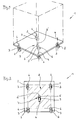
- transport frame 1 comprises all types of mobile transport frames 1 that can be moved by hand. These include in particular all mobile platforms, as shown in FIG. 1, all transport containers from the platform of which walls or frames extend upwards and which are intended for carrying further storage facilities or the like.
- Transport racks 1 in the sense of the innovation also mean all transport trolleys, shopping carts, luggage transport trolleys or other roller racks. All of these transport frames 1 intended for the transport of goods, objects, goods, etc. are equipped with at least three rollers 2, the wheel forks 3 of which can each be pivoted about a horizontal axis 4 in a known manner. Such rollers 2 are usually referred to as castors.
- the rollers 2 are arranged on the transport frame 1 at regular intervals.
- a roller 5 is arranged, which is also located on the running plane of the rollers 2 and which is also equipped with a wheel fork 3 pivotable about a vertical axis 4 '.
- the steering locking device 7 is in Active connection.
- the steering locking device 7, not shown, is in contact with the wheel 6 of the roller 5, which is mounted in the wheel fork 3. In a known manner, the steering locking device 7 reacts to the running direction of the wheel 6.
- the rotation of the wheel 6 in one direction locks the Wheel fork 3 of the roller 5 through the steering locking device 7, so that the roller 5 and thus its wheel fork 3 constantly assumes a predetermined running direction.
- Rotation of the impeller in the other direction causes the wheel fork 3 of the roller 5 to be released by the steering locking device 7, so that the wheel fork 3 of the roller 5 can be pivoted about the vertical axis 4.
- the roller 5 arranged within the floor plan 8 is so operatively connected to the steering locking device 7 that this on the changing direction of the impeller 6 of the roller 5 reacting in an alternating manner, the wheel fork 3 of the roller 5 either locked or released for pivoting about the vertical axis 4 '.
- the steering locking device 7 can be designed such that the wheel fork 3 of the roller 5 can be locked in two, preferably opposite, or pointing in more than two running directions. In order to be able to avoid uneven ground when driving the transport frame 1, it proves to be expedient to arrange the roller 5 or its impeller 6 on the transport frame 1 exactly or approximately vertically.
Landscapes
- Engineering & Computer Science (AREA)
- Mechanical Engineering (AREA)
- Chemical & Material Sciences (AREA)
- Combustion & Propulsion (AREA)
- Transportation (AREA)
- Handcart (AREA)
Applications Claiming Priority (4)
| Application Number | Priority Date | Filing Date | Title |
|---|---|---|---|
| DE1995133463 DE19533463A1 (de) | 1995-09-09 | 1995-09-09 | Transportgestell |
| DE19533463 | 1995-09-09 | ||
| DE29516190U DE29516190U1 (de) | 1995-10-12 | 1995-10-12 | Transportgestell |
| DE29516190U | 1995-10-12 |
Publications (2)
| Publication Number | Publication Date |
|---|---|
| EP0788897A2 true EP0788897A2 (fr) | 1997-08-13 |
| EP0788897A3 EP0788897A3 (fr) | 1998-05-20 |
Family
ID=26018441
Family Applications (1)
| Application Number | Title | Priority Date | Filing Date |
|---|---|---|---|
| EP96114035A Withdrawn EP0788897A3 (fr) | 1995-09-09 | 1996-09-03 | Chariot de transport |
Country Status (1)
| Country | Link |
|---|---|
| EP (1) | EP0788897A3 (fr) |
Cited By (1)
| Publication number | Priority date | Publication date | Assignee | Title |
|---|---|---|---|---|
| US8079606B2 (en) | 2004-05-03 | 2011-12-20 | Inautec Pty Limited | Trolley with a swivable guide wheel |
Citations (7)
| Publication number | Priority date | Publication date | Assignee | Title |
|---|---|---|---|---|
| JPS55156702A (en) | 1979-05-25 | 1980-12-06 | Natsuo Morita | Wheel device |
| GB2106378A (en) | 1981-07-21 | 1983-04-13 | Natsuo Morita | Castors |
| US4580800A (en) | 1984-05-16 | 1986-04-08 | Kart Guard Internationale, Inc. | Shopping cart security device |
| EP0352647A2 (fr) | 1988-07-28 | 1990-01-31 | Wanzl Metallwarenfabrik Gmbh | Chariot de transport empilable |
| EP0370716A1 (fr) | 1988-11-22 | 1990-05-30 | Herok-Rjk Limited | Roue à pivot |
| EP0424234A1 (fr) | 1989-10-17 | 1991-04-24 | GUITEL-ETIENNE MOBILOR Société Anonyme | Roulette pivotante pour chariot |
| EP0562264A1 (fr) | 1992-03-26 | 1993-09-29 | Wanzl GmbH & Co. Entwicklungs-KG | Chariot de transport avec commande à main |
Family Cites Families (4)
| Publication number | Priority date | Publication date | Assignee | Title |
|---|---|---|---|---|
| US5033757A (en) * | 1989-06-10 | 1991-07-23 | Lloyd Gerald E | Trolley |
| JPH0662087B2 (ja) * | 1990-03-16 | 1994-08-17 | 株式会社キョードー | 台 車 |
| WO1993025398A1 (fr) * | 1992-06-10 | 1993-12-23 | Lloyd Gerald E | Ensemble roue de guidage pour chariot et chariot ainsi equipe |
| US5348326A (en) * | 1993-03-02 | 1994-09-20 | Hill-Rom Company, Inc. | Carrier with deployable center wheels |
-
1996
- 1996-09-03 EP EP96114035A patent/EP0788897A3/fr not_active Withdrawn
Patent Citations (7)
| Publication number | Priority date | Publication date | Assignee | Title |
|---|---|---|---|---|
| JPS55156702A (en) | 1979-05-25 | 1980-12-06 | Natsuo Morita | Wheel device |
| GB2106378A (en) | 1981-07-21 | 1983-04-13 | Natsuo Morita | Castors |
| US4580800A (en) | 1984-05-16 | 1986-04-08 | Kart Guard Internationale, Inc. | Shopping cart security device |
| EP0352647A2 (fr) | 1988-07-28 | 1990-01-31 | Wanzl Metallwarenfabrik Gmbh | Chariot de transport empilable |
| EP0370716A1 (fr) | 1988-11-22 | 1990-05-30 | Herok-Rjk Limited | Roue à pivot |
| EP0424234A1 (fr) | 1989-10-17 | 1991-04-24 | GUITEL-ETIENNE MOBILOR Société Anonyme | Roulette pivotante pour chariot |
| EP0562264A1 (fr) | 1992-03-26 | 1993-09-29 | Wanzl GmbH & Co. Entwicklungs-KG | Chariot de transport avec commande à main |
Cited By (1)
| Publication number | Priority date | Publication date | Assignee | Title |
|---|---|---|---|---|
| US8079606B2 (en) | 2004-05-03 | 2011-12-20 | Inautec Pty Limited | Trolley with a swivable guide wheel |
Also Published As
| Publication number | Publication date |
|---|---|
| EP0788897A3 (fr) | 1998-05-20 |
Similar Documents
| Publication | Publication Date | Title |
|---|---|---|
| EP0352647B1 (fr) | Chariot de transport empilable | |
| EP1003663B1 (fr) | Chariot de transport deplacable manuellement | |
| EP3426593A1 (fr) | Engin de transport autoguidé | |
| DE3803626C2 (fr) | ||
| DE4126728C2 (de) | Hebe- und Förderfahrzeug | |
| EP0569988B1 (fr) | Chariot de transport pour objets de type palette | |
| DE19533463A1 (de) | Transportgestell | |
| AT523117A1 (de) | Fahrerlose transporteinrichtung zum transportieren eines ladungsträgers | |
| EP1886894B1 (fr) | Chariot de transport pouvant être déplacé à la main | |
| EP0633176B1 (fr) | Système de transport | |
| AT501909B1 (de) | Vorrichtung zum transport von flächigen gütern | |
| DE3437854C2 (fr) | ||
| DE29516190U1 (de) | Transportgestell | |
| EP0927676B1 (fr) | Chariot de transport emboítable | |
| DE3502194A1 (de) | Von hand bewegbarer transportwagen | |
| EP0891912A1 (fr) | Chariot de transport emboítable | |
| DE7917706U1 (de) | Transportwagen | |
| DE4439299C2 (de) | Plattenwagen | |
| EP1318028B1 (fr) | Dispositif à rouleaux pour chariot | |
| DE8903451U1 (de) | Mit entsprechenden Wagen schachtelbarer Schubgepäckwagen | |
| DE2716624A1 (de) | Hubroller | |
| DE4205023A1 (de) | Transportkarre fuer unterfahrbare gegenstaende | |
| DE19909355A1 (de) | Palette, sowie Lager- und Transportsystem | |
| DE202021003323U1 (de) | Gerät zum Anheben eines Rollbehälters oder dergleichen sowie Kassentischanordnung | |
| DE4227607A1 (de) | Transportkarre für unterfahrbare Gegenstände |
Legal Events
| Date | Code | Title | Description |
|---|---|---|---|
| PUAI | Public reference made under article 153(3) epc to a published international application that has entered the european phase |
Free format text: ORIGINAL CODE: 0009012 |
|
| AK | Designated contracting states |
Kind code of ref document: A2 Designated state(s): DE FR GB IT |
|
| PUAL | Search report despatched |
Free format text: ORIGINAL CODE: 0009013 |
|
| AK | Designated contracting states |
Kind code of ref document: A3 Designated state(s): DE FR GB IT |
|
| 17P | Request for examination filed |
Effective date: 19980610 |
|
| 17Q | First examination report despatched |
Effective date: 19991104 |
|
| STAA | Information on the status of an ep patent application or granted ep patent |
Free format text: STATUS: THE APPLICATION IS DEEMED TO BE WITHDRAWN |
|
| 18D | Application deemed to be withdrawn |
Effective date: 20000315 |