EP0788968B1 - Nachstellvorrichtung für den Anlegehub eines Bremshebels - Google Patents
Nachstellvorrichtung für den Anlegehub eines Bremshebels Download PDFInfo
- Publication number
- EP0788968B1 EP0788968B1 EP97300379A EP97300379A EP0788968B1 EP 0788968 B1 EP0788968 B1 EP 0788968B1 EP 97300379 A EP97300379 A EP 97300379A EP 97300379 A EP97300379 A EP 97300379A EP 0788968 B1 EP0788968 B1 EP 0788968B1
- Authority
- EP
- European Patent Office
- Prior art keywords
- cable
- adjusting mechanism
- brake lever
- lever arm
- brake
- Prior art date
- Legal status (The legal status is an assumption and is not a legal conclusion. Google has not performed a legal analysis and makes no representation as to the accuracy of the status listed.)
- Expired - Lifetime
Links
- 230000007246 mechanism Effects 0.000 title claims description 155
- 239000000463 material Substances 0.000 claims description 7
- 239000002184 metal Substances 0.000 claims description 4
- 230000007423 decrease Effects 0.000 description 2
- 230000000994 depressogenic effect Effects 0.000 description 2
- 238000005259 measurement Methods 0.000 description 2
- 239000011347 resin Substances 0.000 description 2
- 229920005989 resin Polymers 0.000 description 2
- 230000000881 depressing effect Effects 0.000 description 1
- 230000000694 effects Effects 0.000 description 1
- 230000001788 irregular Effects 0.000 description 1
- 238000004519 manufacturing process Methods 0.000 description 1
- 239000007769 metal material Substances 0.000 description 1
- 208000029278 non-syndromic brachydactyly of fingers Diseases 0.000 description 1
Images


Classifications
-
- B—PERFORMING OPERATIONS; TRANSPORTING
- B62—LAND VEHICLES FOR TRAVELLING OTHERWISE THAN ON RAILS
- B62L—BRAKES SPECIALLY ADAPTED FOR CYCLES
- B62L3/00—Brake-actuating mechanisms; Arrangements thereof
- B62L3/02—Brake-actuating mechanisms; Arrangements thereof for control by a hand lever
-
- Y—GENERAL TAGGING OF NEW TECHNOLOGICAL DEVELOPMENTS; GENERAL TAGGING OF CROSS-SECTIONAL TECHNOLOGIES SPANNING OVER SEVERAL SECTIONS OF THE IPC; TECHNICAL SUBJECTS COVERED BY FORMER USPC CROSS-REFERENCE ART COLLECTIONS [XRACs] AND DIGESTS
- Y10—TECHNICAL SUBJECTS COVERED BY FORMER USPC
- Y10T—TECHNICAL SUBJECTS COVERED BY FORMER US CLASSIFICATION
- Y10T74/00—Machine element or mechanism
- Y10T74/20—Control lever and linkage systems
- Y10T74/20207—Multiple controlling elements for single controlled element
- Y10T74/20256—Steering and controls assemblies
- Y10T74/20268—Reciprocating control elements
- Y10T74/2028—Handle bar type
- Y10T74/20287—Flexible control element
-
- Y—GENERAL TAGGING OF NEW TECHNOLOGICAL DEVELOPMENTS; GENERAL TAGGING OF CROSS-SECTIONAL TECHNOLOGIES SPANNING OVER SEVERAL SECTIONS OF THE IPC; TECHNICAL SUBJECTS COVERED BY FORMER USPC CROSS-REFERENCE ART COLLECTIONS [XRACs] AND DIGESTS
- Y10—TECHNICAL SUBJECTS COVERED BY FORMER USPC
- Y10T—TECHNICAL SUBJECTS COVERED BY FORMER US CLASSIFICATION
- Y10T74/00—Machine element or mechanism
- Y10T74/20—Control lever and linkage systems
- Y10T74/20396—Hand operated
- Y10T74/20402—Flexible transmitter [e.g., Bowden cable]
- Y10T74/2042—Flexible transmitter [e.g., Bowden cable] and hand operator
- Y10T74/20438—Single rotatable lever [e.g., for bicycle brake or derailleur]
Definitions
- the invention relates to a brake lever arm having an adjusting mechanism therein which adjusts the reach of the brake lever arm and the length of the movement of the brake lever arm.
- brake actuating mechanisms for bicycles were merely levers coupled to the handle bar of a bicycle with a cable connected to the lever, the opposite end of the cable being connected to a brake mechanism adjacent to one of the bicycle wheels.
- brake mechanisms and brake actuating mechanisms have become very sophisticated in recent years.
- Brake actuating mechanisms usually include a lever arm mounted to a base member for pivotal movement.
- the base member is typically mounted to a handlebar of a bicycle.
- a cable extends from the brake mechanism to the lever arm.
- the lever arm pivots between a brake engagement position and a brake disengagement position. In the brake engagement position, the cable is pulled by the lever arm so that the brake mechanism is engaged to stop tire rotation. In the brake disengagement position, the cable tension is released and the brake mechanism is disengaged.
- the lever arm is spaced apart from the handlebar by a predetermined distance. In the brake engagement position, the lever arm is closer to the handlebar than it is in the brake disengagement position.
- brake actuation mechanisms which include an adjustment mechanism which allows adjustment of the location of the lever arm when the brake mechanism is in a brake disengagement position.
- the brake disengagement position adjustment is defined as the reach of a lever arm.
- Such reach adjustment mechanisms at least allow for some user adjustable features enabling a manufacturer to manufacture one component that may be used by a variety of bicyclists.
- the stroke of the lever arm is defined as the total distance the lever arm moves from the brake disengagement position to the brake engagement position.
- the stroke length may be small or large depending on many things such as the brake mechanism used, how well the brake mechanism is adjusted, the length of the cable, to name a few.
- Adjustable lever arms appear to fail to provide for the lever arm stroke length. For instance, in the case where the stroke is relatively large and the adjustable lever arm is adjusted to accommodate small hands, the lever arm would be adjusted to be closer to the handlebar in the brake disengagement position. After such an adjustment, the lever arm might contact the handlebar before the brake is engaged causing possible ineffective braking.
- the present invention provides a brake lever mechanism according to claim 1.
- the cable engagement portion and the adjusting mechanism are spaced apart from one another such that a cable extending through the cable guide to the cable engagement portion is selectively engagable with the cable contact point and remains in a spaced apart relationship with the handle portion of the lever arm with the cable in a tensioned state.
- the handle portion has a generally semi-circular shape.
- the adjusting mechanism includes a dial member supported in the support portion of the lever arm and the adjusting mechanism also includes a threaded screw extending from the cable contact point, the threaded screw extending through a central threaded aperture formed in the dial member.
- the cable which extends from the cable guide to the cable engagement portion, is in a tensioned state the cable is spaced apart from the handle portion of the lever arm providing limited protection for a user's hand engaged with the handle portion.
- the brake lever mechanism further includes a fine adjusting mechanism extending through a portion of the base member for engagement with the support portion, wherein the fine adjusting mechanism adjusts the relative position between the lever arm and the cable guide with the lever arm in the brake dis-engagement position.
- the brake lever mechanism further includes a fine adjusting mechanism extending through a portion of the base member for engagement with the adjusting mechanism, wherein the fine adjusting mechanism adjusts the relative position between the lever arm and the cable guide with the lever arm in the brake dis-engagement position.
- the brake lever mechanism further includes a cable hook connected to the cable engagement portion and the cable.
- the handle portion includes a single finger grip engaging portion.
- the single finger grip engaging portion has a generally semi-circular shape.
- the adjusting mechanism further includes a body portion with the cable contact point defined on a portion thereon, a dial member supported in the support portion, and a threaded screw extending from proximate the body portion, the threaded screw extending through a central threaded aperture formed in the dial member.
- the adjusting mechanism further includes a body portion with the cable contact point defined on one portion thereof and a spring biased tapered pin extending through the body portion and through a portion of the support portion. Further, the body portion is moveable from a first position a first distance away from the pivot point to a second position a second distance away from the pivot point in response to depression of the spring biased tapered pin.
- the adjusting mechanism further includes a body portion with the cable contact point defined on one portion thereof and a second cable contact point defined on another portion thereof and a pin member extending through an off-center portion of the body portion, the pin member being rigidly attached to the body portion and the pin member further extending through apertures formed in the support portion.
- the body portion and the pin member are selectively rotatable from a first position to a second position such that:
- the body portion is at least partially made of a plastic material and the cable contact point is defined on the plastic material.
- the body portion is formed from metal.
- the brake lever mechanism includes a fine adjusting mechanism extending through a portion of the base member for engagement with the support portion, wherein the fine adjusting mechanism adjusts the relative position between the lever arm and the cable guide with the lever arm in the brake dis-engagement position.
- the brake lever mechanism includes a fine adjusting mechanism through a portion of the base member for engagement with the adjusting mechanism, wherein the fine adjusting mechanism adjusts the relative position between the lever arm and the cable guide with the lever arm in the brake dis-engagement position.
- a brake lever mechanism in one aspect of the present invention, includes a base member formed with a cable guide and the base member having a pivot point defined thereon spaced apart from the cable guide.
- the brake lever also includes a lever arm formed with a handle portion and a support portion, the support portion mounted for pivotal movement on the pivot point from a brake dis-engagement position to a brake engagement position, the support portion formed with a slot therein, and the handle portion formed with a cable connector.
- Mounted within the slot is an adjusting mechanism, the adjusting mechanism having a cable contact point, wherein the adjusting mechanism adjusts the relative position between the cable contact point and the pivot point.
- a fine adjusting mechanism extends through a portion of the base member for engagement with the support portion.
- the fine adjusting mechanism adjusts the relative position between the lever arm and the cable guide with the lever arm in the brake dis-engagement position.
- the fine adjusting mechanism extends through a portion of the base member for engagement with the adjusting mechanism, wherein the fine adjusting mechanism adjusts the relative position between the lever arm and the cable guide with the lever arm in the brake dis-engagement position.
- the support portion of the lever arm is formed with a second slot generally parallel to the slot.
- the adjusting mechanism is formed with a pin extending through the slot and the adjusting mechanism includes a screw extending though the second slot.
- the slot extends lengthwise in the support portion from a point proximate the pivot point away from the pivot point.
- the adjusting mechanism includes a first portion having at least one pin member which extends through the slot in the support portion, and the adjusting mechanism includes a contact member attached to the first portion, the cable contact point being formed on the contact member.
- the cable guide includes an aperture extending through a portion of the base member and a cable length adjusting member encircling one end of the aperture on threads formed on the base member.
- the support portion of the lever arm includes generally parallel first and second support portions spaced apart from one another extending from the lever portion, the slot having parallel first and second slots formed in the first and second support portions, respectively, the adjusting mechanism being disposed between the first and second support portions, and the adjusting mechanism having a pin which extends through the first and second slots.
- the. first and second support portions are formed with third and fourth slots generally parallel to the first and second slot, respectively, and the adjusting mechanism includes a screw extending through the third slot and the adjusting mechanism includes a threaded member engaging the screw extending though the fourth slot.
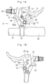
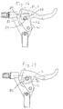
- a bicycle brake mechanism 5 that includes a base 10 that is connected to a bicycle handlebar 15.
- the handlebar 15 also includes a grip 20 to accommodate a bicyclist's hand (not shown).
- a pivot pin 25 extends through the base 10 and a lever arm 30. The lever arm 30 pivots freely about the pivot pin 25.
- the lever arm 30 has a U-shaped cross-section, as shown in Fig. 2.
- the lever arm 30 is therefore has a generally hollow interior and has generally parallel opposing sides 31 and 32.
- the side 32 includes a first slot 35 and a third slot 36, as shown in Fig. 1B.
- the side 31 includes a second slot 38, which has an irregular shape, as will be described in greater detail below.
- Disposed between the two sides 31 and 32 is an adjusting mechanism 40, which is also described in greater detail below.
- the lever arm 30 is also formed with a cable retainer 42 which accommodates and retains the ball end 44 of a cable (not shown in Figs. 1A and 1B).
- a cable not shown in Figs. 1A and 1B.
- the ball end 44 of the cable end is shown but the cable is not shown for greater clarity.
- the cable C is shown in Figs. 4 - 12, and is described in greater detail below.
- the base 10 also includes an extending portion 46 which has a distal end 48.
- the distal end 48 is formed with a threaded bore 49 through which a cable adjusting mechanism 50 extends.
- An adjusting screw 52 extends through the extending portion 46, as is described in greater detail below.
- the adjusting mechanism 40 is shown in cross section in Fig. 2, and is also shown removed from the lever arm 30 in Figs. 3A, 3B and 3C.
- the adjusting mechanism 40 includes a main body 54 which has a generally U-shape in cross-section, as shown in Fig. 3C.
- the main body 54 includes a pin 56 extending though holes formed on either side of the main body 54 and a screw 58 also extending though the main body 54, the screw 58 engaging threads formed in the main body 54.
- the screw 58 also extends through a contact body 60.
- the pin 56 is fitted tightly within the main body 54 by, for instance, press fitting the pin 56 in holes formed in the main body 54.
- the contact body 60 generally has a T-shape, as shown in Fig. 3B, the lower portion 60a of the contact body 60 extending into the interior of the main body 54.
- the contact body 60 as indicated in Fig. 2, is made of a resin or plastic material.
- the upper portion of the contact body 60 is formed with a recess 62 that extends the length of the upper portion of the contact body 60.
- the pin 56 extends into the first slot 35 formed in the side 32. Further, the screw 58 extends into the third slot 36 formed in the side 32 and the head 58a of the screw 58 extends through the second slot 38 formed in the side 31. When the screw 58 is loosened, the adjusting mechanism 40 is able to slide freely within the length of the slots 35, 36 and 38.
- the adjusting mechanism 40 is configured to move to three positions within the lever arm 30.
- the second slot 38 is formed with three rounded sections 38a, 38b and 38c to accommodate a screw head 58a formed on the end of the screw 58.
- the screw 58 In order to change the position of the adjusting mechanism 40, the screw 58 must be loosened so that the head 58a of the screw 58 extends above the surface of the side 31 of the lever arm 30. With the screw 58 loose, the adjusting mechanism 40 is able to slide within the confines of the first slot 35 and the second slot 38.
- the screw 58 may be tightened so that the head 58a extends into one of the three rounded sections 38a, 38b or 38c, each of the rounded sections corresponding to the three positions, which are described in greater detail below.
- the second slot 38 may be provided with only two rounded sections or may be formed with four or more rounded sections to provide corresponding numbers of adjustment positions for the adjusting mechanism 40.
- the screw 58 may be replaced with a spring loaded pin which may be urged by a spring into the rounded sections 38a, 38b or 38c and by pushing on the spring loaded pin, the adjusting mechanism 40 may be moved into a desired position.
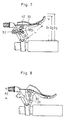
- Figs. 4 through 12 depict the present invention in an alternate embodiment where the first slot 35 has also been formed in the side 31 and the pin 56 extends into the first slot 35 formed in the side 31. Further, the cable C connects to the lever arm 30 in an alternate manner.
- Figs. 4 - 12 the three positions of the adjusting mechanism 40 are depicted. For instance, in Figs. 4 - 6 the adjusting mechanism 40 is shown in a first position with the head 58a disposed in the rounded section 38a. In Figs. 7 - 9 the adjusting mechanism 40 is shown in a second position with the head 58a disposed in the rounded section 38b. In Figs. 10 - 12 the adjusting mechanism 40 is shown in a third position with the head 58a disposed in the rounded section 38c.
- Fig. 4 shows the lever arm 30 in a first brake disengagement position where the lever arm 30 is a distance D 1 away from the handlebar grip 20.
- a brake lever arm distance L is defined from the center of the pivot pin 25 to the center of the cable end 44. It should be noted that the brake lever arm distance L is constant throughout all of the various positions depicted in Figs. 4 through 12.
- Fig 5 shows the brake lever arm 30 in an intermediate position between the brake engagement and brake disengagement positions.
- a first adjustable lever distance A 1 is defined from the center of the pivot pin 25 to the recess 62 where the cable C contacts the contact body 60. It should be appreciated that the first adjustable lever distance A 1 is constant in Figs. 4, 5 and 6 where the adjusting mechanism 40 is positioned with the screw head 58a disposed in the first rounded portion 38a of the second slot 38.
- Fig 7 shows the brake lever arm in a second brake disengagement position, where the lever arm 30 is a distance D 2 away from the handlebar grip 20 due to the head 58a of the screw 58 being positioned in the second rounded portion 38b of the slot 38.
- Fig 8 shows the brake lever arm in an intermediate position.
- a second adjustable lever distance A 2 is defined from the center of the pivot pin 25 to the recess 62 where the cable C contacts the contact body 60. It should be appreciated that the second adjustable lever distance A 2 is constant in Figs. 7, 8 and 9 where the adjusting mechanism 40 is positioned with the screw head 58a disposed in the second rounded portion 38b of the second slot 38.
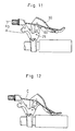
- Fig. 10 shows the brake lever arm in a third brake disengagement position, with the adjusting mechanism 40 in a third position where the head 58a of the screw 58 is disposed in the third rounded section 38c of the slot 38.
- the lever arm 30 is a distance D 3 away from the handlebar grip 20.
- Fig 11 shows the brake lever arm in an intermediate position.
- a third adjustable lever distance A 3 is defined from the center of the pivot pin 25 to the recess 62 where the cable C contacts the contact body 60. It should be appreciated that the third adjustable lever distance A 3 is constant in Figs. 10, 11 and 12 where the adjusting mechanism 40 is positioned with the screw head 58a disposed in the third rounded portion 38c of the second slot 38.
- the various positions of the lever arm distance D 1 , D 2 , and D 3 represent the reach of the lever arm 30.
- the reach distance D 1 , D 2 or D 3 is easily adjusted by moving the adjusting mechanism 40 into any one of the three rounded sections 38a, 38b or 38c. Adjustment of the reach distance D 1 , D 2 or D 3 also alters the stroke length or total movement of the lever arm 30 due to the setting of the adjustable lever distances A 1 , A 2 or A 3 .
- the adjustable lever distances alter the stroke length of the lever arm 30 by contacting the cable at points having differing distances from the pivot pin 25. The movement of the cable C is directly proportional to the size of the adjustable lever distances A 1 , A 2 or A 3 .
- the adjustable lever distance A 1 has a relatively large value and therefore, as the lever arm 30 moves, the cable C will move about the pivot pin 25 a corresponding short stroke length until the brake mechanism (not shown) is engaged.
- the adjustable lever distance A 2 has an intermediate value and therefore, as the lever arm 30 moves, the cable C will move about the pivot pin 25 a corresponding intermediate stroke length until the brake mechanism (not shown) is engaged.
- the adjustable lever distance A 3 has a relatively small value and therefore, as the lever arm 30 moves, the cable C will move about the pivot pin 25 a corresponding long stroke length until the brake mechanism (not shown) is engaged.
- the brake disengage position distance D 1 provides a short reach for a bicyclist, with the lever arm 30 being relatively close to the handlebar grip 20.
- the brake disengage position distance D 3 provides a long reach for a bicyclist, with the lever arm 30 being at a relatively large distance from the handlebar grip 20.
- the adjusting screw 52 is shown contacting the adjusting mechanism 40. However, alternatively, the adjusting screw 52 may be configured to contact one or both of the sides 31 and 32.
- the adjusting screw 52 is mounted in the present invention in part to provide for fine adjustment of the reach of the lever arm 30.
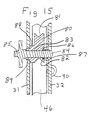
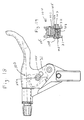
- an adjusting mechanism includes a contact body 80 formed with a first contact portion 81 and a second contact portion 82, shown in Fig. 15.
- the contact body 80 is formed with an aperture 83 through which a pin 84 extends.
- the pin 84 is tightly fitted in to the aperture 83 such that the pin 84 and the contact body 80 rotate together, as is described in greater detail below.
- the pin 84 is formed with a dial 85.
- the contact body 80 is also formed with a recess 86 which accommodates a coil spring 87.
- the contact body 80 also includes a circular portion 88 and a shoulder portion 89.
- the shoulder portion 89 has a circular shape but includes two generally flat surfaces, as depicted in Figs. 16 and 17. In Figs. 16 and 17, the dial 85 and the pin 84 have been removed in order to show the shape of the shoulder portion 89 and an aperture 92.
- the aperture 92 is formed in the side 31 of the lever arm.
- the aperture 92 has generally the same shape as the shoulder portion 89.
- the extending portion 46 in this embodiment is formed with a flange 90.
- the flange 90 has an aperture through which the fine adjusting screw 52 extends.
- the adjusting screw 52 contacts an edge of the side 32 of the lever arm.
- the adjusting mechanism operates as now described.
- the contact body 80 may be rotated 180° by depressing the dial 85 and rotating it. Pressing the dial 85 causes the contact body 80 to compress the coil spring 87 against the inner surface of the side 32 (see Fig. 15).
- the shoulder portion 89 is pushed out of the aperture 92, thus allowing the dial 85 and the contact body 80 to be rotated.
- the coil spring 87 urges the shoulder portion 89 into the aperture 92, thus locking the contact body 80 into position.
- FIG. 16 and 17 show schematically the effect and the positions the contact body 80 may be set to. Further, Fig. 16 shows the first contact portion 81 contacting the cable C. Fig. 17 shows the second contact portion 82 contacting the cable C. Thus rotation of the contact body 80 in this embodiment changes the distance between the pivot point of the lever arm and the contact point of the contact body 80.
- the contact body 80 is shown as being made of metal. However, it should be understood that the contact body 80 may be made of a plastic or resin material or combinations of plastic and metal materials. Further, it should be appreciated that more than two contact portions could easily be formed on the contact body 80. For instance, three or four contact portions could be formed on the contact body 80.
- FIGs. 18 and 19 depict yet another embodiment of the present invention where an adjusting mechanism 100 includes a contact body 101 having an aperture 102 and a recess 103 formed therein.
- a pin 104 extends through the aperture 102 and the recess 103 and also through generally similarly shaped openings 105 formed in the sides 31 and 32 of the lever arm.
- the openings 105 include two large portions, as depicted in Fig. 18. Due to the shape of the end of the pin 104, part of the opening 105 is shown in dashed lines in Fig. 18.
- One end of the pin 104 is force fitted into a cylindrically shaped cap 106 which has a generally tapered outer surface, as shown in Fig. 19.
- the cap 106 and the recess 103 confine a coil spring 107 therebetween.
- the adjusting mechanism 100 operates as follows. When the cap 106 is depressed, the coil spring 107 is compressed within the recess 103. Due to the tapered shape of the outer surface of the cap 106, once the cap 106 has been depressed, it may be moved back and forth between the two portions of the opening 105. Similarly, the opposite end of the pin 104 may also be moved therewith. In this manner the adjusting mechanism may be moved between at least two positions corresponding to the shape of the openings 105. In Fig. 18, the adjusting mechanism 100 is shown in an outer position, generally corresponding to the position of the adjusting mechanism 40 depicted in Figs. 1A, 4, 5 and 6 of the first embodiment. In Fig.
- the opening 105 is such that only two positions of the adjusting mechanism 100 are possible. However it should be appreciated that the opening 105 could easily be made similar to the slot 38 depicted in Fig. 1A to make it possible to position the adjusting mechanism 100 in more than two positions.
- an adjusting mechanism 120 includes a dial 121 having a central threaded aperture through which a threaded pin 122 extends.
- the threaded pin 122 extends into an aperture 123 formed in the lever arm 130.
- the threaded pin 122 is free to move within the aperture 123 but its movement is confined by engagement with the threaded aperture formed in the dial 121.
- the dial 121 is disposed in a slot formed in the lever arm 130.
- the threaded pin 122 is connected to a contact body 124 by, for instance a pin.
- the contact body 124 is disposed within an extending member 128 which is fixed to the lever arm 130.
- the extending member 128 is formed with two generally parallel slots 126.
- a pin 125 extends through the contact body 124 and the slots 126 to guide movement of the contact body 124 within the extending member 128.
- the adjusting mechanism 120 operates generally as follows. In order to adjust the position of the contact body 124, the dial 121 may be rotated. Rotation of the dial 121 causes movement of the threaded pin 122 within the aperture 123. Movement of the threaded pin 122 in turn causes movement of the contact body 124.
- the lever arm 130 has a semi-circular handle portion 136 having a center point 137 which is positioned between the handle portion 136 and the cable C. Due to the shape of the handle portion 136, the cable C provides limited protection against debris possibly hitting a hand or finger grasping the handle portion 136. Preferably, the handle portion 136 is sized to accommodate one finger, although larger sizes are within the scope of the invention.
- contact body 124 could be made from any of a variety of materials, such as metal, plastic or combinations thereof.
- the present invention provides a simple and easy way to adjust the reach of a lever arm.
- the present invention also provides a simple and easy way to adjust the stroke length of a lever arm.
- the present invention provides a simple and easy means for simultaneously adjusting both the reach and the stroke of a lever arm.
- the present invention also provides a means for fine adjustment of a lever arm in a brake disengage position to accommodate various sized bicyclists with differing sized hands.
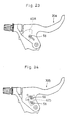
- FIG. 23 Another alternate embodiment is depicted in Fig. 23, where an adjusting mechanism 40a is mounted within a lever arm 30a by the screw 58.
- the screw is completely removed before the adjustment mechanism 40a may be moved to different positions. Once in position, the screw 58 must be re-installed.
- two screws 58 are used to secure an adjusting mechanism 40b into position in a lever arm 30b.
Landscapes
- Engineering & Computer Science (AREA)
- Mechanical Engineering (AREA)
- Steering Devices For Bicycles And Motorcycles (AREA)
- Mechanical Control Devices (AREA)
- Braking Elements And Transmission Devices (AREA)
Claims (24)
- Ein Bremshebelmechanismus, bestehend aus:dadurch gekennzeichnet, dass der Mechanismus einen Einstellmechanismus (40, 40a, 40b, 50, 100, 120) beinhaltet, der in dem Stützteil (31, 32) montiert ist, wobei der Einstellmechanismus (40, 40a, 40b, 50, 100, 120) einen Kabelkontaktpunkt (60, 80, 101, 124) aufweist, wobei der Einstellmechanismus (40, 40a, 40b, 50, 100, 120) die relative Stellung zwischen dem Kabelkontaktpunkt (60, 80, 101, 124) und dem Schwenkpunkt (25) einstellt.einem Grundelement (10), das mit einer Kabelführung (50) geformt ist, und wobei das Grundelement (10) einen Schwenkpunkt (25) aufweist, der darauf mit Abstand von der Kabelführung (50) angeordnet und festgelegt ist;einem Hebelarm (30, 130), der mit einem Griffteil (136) und einem Stützteil (31, 32) geformt ist, wobei der Stützteil (31, 32) zur Schwenkbewegung von einer ausgerückten Bremsausklinkstellung in eine Bremseingriffsstellung auf dem Schwenkpunkt (25) montiert ist, wobei der Griffteil (30, 130) mit einem Kabelverbindungsstück (42) geformt ist;
- Bremshebelmechanismus gemäß Anspruch 1, wobei das Kabelverbindungsstück (42) und der Einstellmechanismus (40, 40a, 40b, 50, 100, 120) mit Abstand voneinander angeordnet sind, so dass ein Kabel (C), welches sich durch die Kabelführung (50) bis zu dem Kabelverbindungsstück (42) erstreckt, selektiv mit dem Kabelkontaktpunkt (60, 80, 101, 124) eingreifbar ist und in einer mit Zwischenraum angeordneten Beziehung mit dem Griffteil (136) des Hebelarms (30, 130) verbleibt, wobei sich das Kabel (C) in einem gespannten Zustand befindet.
- Bremshebelmechanismus gemäß Anspruch 1 oder Anspruch 2, wobei der Griffteil (136) eine im Allgemeinen halbrunde Form aufweist.
- Bremshebelmechanismus gemäß einem der vorhergehenden Ansprüche, wobei wenn sich das Kabel (C), welches sich von der Kabelführung (50) zu dem Kabelverbindungsstück (42) erstreckt, in einem gespannten Zustand befindet, das Kabel (C) mit Abstand von dem Griffteil (136) des Hebelarms (30, 130) angeordnet ist, wodurch ein begrenzter Schutz für die Hand eines Benutzers, die in den Griffteil (136) eingreift, bereitgestellt wird.
- Bremshebelmechanismus gemäß einem der vorhergehenden Ansprüche, der einen mit dem Kabelverbindungsstück (42) und dem Kabel (C) verbundenen Kabelhaken beinhaltet.
- Bremshebelmechanismus gemäß einem der vorhergehenden Ansprüche, wobei der Griffteil aus einem Eingriffsteil (136) zum Greifen mit einem einzelnen Finger besteht.
- Bremshebelmechanismus gemäß Anspruch 6, wobei der Eingriffsteil (136) zum Greifen mit einem einzelnen Finger eine im Allgemeinen halbrunde Form aufweist.
- Bremshebelmechanismus gemäß einem der vorhergehenden Ansprüche, wobei der Einstellmechanismus (120) ein Skalenscheibenelement (121) beinhaltet, das in dem Stützteil (31, 32) des Hebelarms (30, 130) gestützt ist, und wobei der Einstellmechanismus (120) außerdem eine Gewindeschraube (122) beinhaltet, die sich von dem Kabelverbindungsstück (42) erstreckt, wobei sich die Gewindeschraube (122) durch eine zentrale Gewindeöffnung (123), die in dem Skalenscheibenelement (121) geformt ist, erstreckt.
- Bremshebelmechanismus gemäß einem der Ansprüche 1 bis 7, wobei der Einstellmechanismus (120) Folgendes beinhaltet:einen Körperteil (124), wobei der Kabelkontaktpunkt auf einem Teil darauf festgelegt ist;ein Skalenscheibenelement (121), das in dem Stützteil (31, 32) gestützt ist; undeine Gewindeschraube (122), die sich unmittelbar von dem Körperteil (124) erstreckt, wobei sich die Gewindeschraube (122) durch eine zentrale Gewindeöffnung (123), die in dem Skalenscheibenelement (121) geformt ist, erstreckt.
- Bremshebelmechanismus gemäß einem der Ansprüche 1 bis 7, wobei der Einstellmechanismus (100) Folgendes beinhaltet:einen Körperteil (101), wobei der Kabelkontaktpunkt auf einem Teil davon festgelegt ist;einen durch eine Feder vorgespannten, spitz zulaufenden Stift (104, 106), der sich durch den Körperteil (101) und durch einen Teil des Stützteils (31, 32) erstreckt; und wobeider Körperteil (101) aus einer ersten Stellung in einer ersten Entfernung von dem Schwenkpunkt (25) entfernt in eine zweite Stellung in einer zweiten Entfernung von dem Schwenkpunkt (25) entfernt, als Reaktion auf das Herunterdrücken des durch eine Feder vorgespannten, spitz zulaufenden Stifts (104, 106), bewegbar ist.
- Bremshebelmechanismus gemäß einem der Ansprüche 1 bis 7, wobei der Einstellmechanismus Folgendes beinhaltet:einen Körperteil (80), wobei der Kabelkontaktpunkt (81) auf einem Teil davon festgelegt ist und ein zweiter Kabelkontaktpunkt (82) auf einem anderen Teil davon festgelegt ist; undein Stiftelement (84), das sich durch einen von der Mitte versetzten Teil (83) des Körperteils (80) erstreckt, wobei das Stiftelement (84) starr an dem Körperteil (80) befestigt ist, und wobei sich das Stiftelement (84) ferner durch Öffnungen, die in dem Stützteil (31, 32) geformt sind, erstreckt.
- Bremshebelmechanismus gemäß Anspruch 11, wobei der Körperteil (80) und das Stiftelement (84) wahlweise von einer ersten Stellung in eine zweite Stellung drehbar sind, so dass:der Kabelkontaktpunkt (81) in der ersten Stellung eine erste Entfernung von dem Schwenkpunkt (25) entfernt liegt;der zweite Kabelkontaktpunkt (82) in der zweiten Stellung eine zweite Entfernung von dem Schwenkpunkt (25) entfernt liegt;der Kabelkontaktpunkt (81) in der ersten Stellung so konfiguriert ist, dass er als Reaktion auf eine Bewegung des Hebelarms (30, 130) in ein Kabel (C), das mit dem Kabelverbindungsstück (42) verbunden ist, eingreift; undder zweite Kabelkontaktpunkt (82) in der zweiten Stellung so konfiguriert ist, dass er als Reaktion auf eine Bewegung des Hebelarms (30, 130) in das Kabel (C) eingreift.
- Bremshebelmechanismus gemäß einem der Ansprüche 9 bis 12, wobei der Körperteil (80) mindestens teilweise aus einem Kunststoffmaterial hergestellt ist und wobei der Kabelkontaktpunkt (81, 82) auf dem Kunststoffmaterial festgelegt ist.
- Bremshebelmechanismus gemäß einem der Ansprüche 9 bis 12, wobei der Körperteil (80) aus Metall geformt ist.
- Bremshebelmechanismus gemäß einem der vorhergehenden Ansprüche, der einen Feineinstellmechanismus (52) beinhaltet, der sich durch einen Teil (46) des Grundelements (10) zum Eingriff mit dem Stützteil (31, 32) und/oder dem Einstellmechanismus (40, 40a, 40b, 50, 100, 120) erstreckt, wobei der Feineinstellmechanismus (52), die relative Stellung zwischen dem Bremsarm (30, 130) und der Kabelführung (50) einstellt, wenn sich der Hebelarm (30, 130) in der Bremseinklinkstellung befindet.
- Bremshebelmechanismus gemäß einem der Ansprüche 1 bis 7, wobei der Stützteil (31, 32) mit einem Schlitz (35) geformt ist und der Einstellmechanismus (40) auf wahlweise Bewegung entlang des Schlitzes (35) beschränkt ist.
- Bremshebelmechanismus gemäß Anspruch 16, wobei der Stützteil (31, 32) des Hebelarms (30, 130) mit einem zweiten Schlitz (38) geformt ist, der im Allgemeinen parallel zum Schlitz (35) liegt, und wobei der Einstellmechanismus (40) mit einem Stift (56) geformt ist, der sich durch den Schlitz (35) erstreckt, und wobei der Einstellmechanismus (40) eine Schraube (58) beinhaltet, die sich durch den zweiten Schlitz (38) erstreckt.
- Bremshebelmechanismus gemäß einem der Ansprüche 16 oder 17, wobei sich der Schlitz (35) längs in dem Stützteil (31, 32) von einer Stelle, die unmittelbar bei dem Schwenkpunkt (25) liegt, von dem Schwenkpunkt (25) weg erstreckt.
- Bremshebelmechanismus gemäß einem der Ansprüche 16 bis 18, wobei der Einstellmechanismus (40) aus einem ersten Teil (54) besteht, der mindestens ein Stiftelement (56) aufweist, das sich durch den Schlitz (35) in dem Stützteil (31, 32) erstreckt, und wobei der Einstellmechanismus (40) ein Kontaktelement (60) beinhaltet, das an dem ersten Teil (54) befestigt ist, wobei der Kabelkontaktpunkt auf dem Kontaktteil (60) geformt ist.
- Bremshebelmechanismus gemäß Anspruch 16, wobei der Stützteil (31, 32) des Bremsarms aus im Allgemeinen parallelen ersten und zweiten Stützteilen (31, 32) besteht, die mit Abstand voneinander angeordnet sind und sich von dem Griffteil (136) erstrecken, wobei der Schlitz aus parallelen ersten und zweiten Schlitzen (35) besteht, die jeweils in den ersten und zweiten Stützteilen (31, 32) geformt sind, wobei der Einstellmechanismus (40) zwischen den ersten und zweiten Stützteilen (31, 32) angeordnet ist, und wobei der Einstellmechanismus (40) einen Stift (56) aufweist, der sich durch die ersten und zweiten Schlitze (35) erstreckt.
- Bremshebelmechanismus gemäß Anspruch 20, wobei die ersten und zweiten Stützteile (31, 32) mit dritten und vierten Schlitzen (36, 38) geformt sind, die im Allgemeinen jeweils parallel zu den ersten und zweiten Schlitzen (35) liegen, und wobei der Einstellmechanismus (40) eine Schraube (58) beinhaltet, die sich durch die dritten und vierten Schlitze (36, 38) erstreckt.
- Bremshebelmechanismus gemäß einem der Ansprüche 1 bis 7, wobei der Stützteil (31, 32) mit einer Vielzahl von Öffnungen geformt ist, und wobei der Einstellmechanismus (40a) mittels einer Schraube (58), die sich durch eine der Öffnungen und den Einstellmechanismus (40a) erstreckt, innerhalb des Stützteils (31, 32) montiert ist.
- Bremshebelmechanismus gemäß einem der Ansprüche 1 bis 7, wobei der Stützteil (31, 32) mit einer Vielzahl von Öffnungspaaren geformt ist und wobei der Einstellmechanismus (40b) mittels einem Paar Schrauben (58) innerhalb des Stützteils (31, 32) montiert ist, wobei sich jede Schraube (58) des Schraubenpaars durch eines der Öffnungspaare und den Einstellmechanismus (40b) erstreckt.
- Bremshebelmechanismus gemäß einem der vorhergehenden Ansprüche, wobei die Kabelführung aus einer Öffnung (49), die sich durch einen Teil (46) des Grundelements (10) erstreckt, und einem Kabellängen-Einstellelement (50) besteht, das ein Ende der Öffnung (49) auf Gewinden umgibt, die auf dem Grundelement (10) geformt sind.
Applications Claiming Priority (4)
| Application Number | Priority Date | Filing Date | Title |
|---|---|---|---|
| US598578 | 1996-02-12 | ||
| US08/598,578 US6112614A (en) | 1996-02-12 | 1996-02-12 | Brake lever stroke adjusting mechanism |
| US753238 | 1996-11-25 | ||
| US08/753,238 US5865064A (en) | 1996-02-12 | 1996-11-25 | Brake lever stroke adjusting mechanism |
Publications (3)
| Publication Number | Publication Date |
|---|---|
| EP0788968A2 EP0788968A2 (de) | 1997-08-13 |
| EP0788968A3 EP0788968A3 (de) | 1998-07-01 |
| EP0788968B1 true EP0788968B1 (de) | 2003-01-15 |
Family
ID=27083104
Family Applications (1)
| Application Number | Title | Priority Date | Filing Date |
|---|---|---|---|
| EP97300379A Expired - Lifetime EP0788968B1 (de) | 1996-02-12 | 1997-01-21 | Nachstellvorrichtung für den Anlegehub eines Bremshebels |
Country Status (4)
| Country | Link |
|---|---|
| US (1) | US5865064A (de) |
| EP (1) | EP0788968B1 (de) |
| CN (1) | CN1077856C (de) |
| DE (1) | DE69718357T2 (de) |
Cited By (1)
| Publication number | Priority date | Publication date | Assignee | Title |
|---|---|---|---|---|
| DE102019130146B4 (de) | 2019-11-08 | 2022-07-21 | Schaeffler Technologies AG & Co. KG | Verfahren zur Befestigung eines Bremshebels an einem Lenker eines Fahrzeugs mit einer Montageanordnung und Montageanordnung zur Durchführung des Verfahrens |
Families Citing this family (12)
| Publication number | Priority date | Publication date | Assignee | Title |
|---|---|---|---|---|
| US5839544A (en) * | 1997-05-19 | 1998-11-24 | Shimano Inc. | Brake lever having a rapid brake shoe clearance adjusting mechanism |
| EP0894702B1 (de) * | 1997-07-30 | 2006-06-21 | William Bolick | Kabelsteuerung |
| USD442529S1 (en) | 2000-02-29 | 2001-05-22 | Shimano Inc. | Portion of a disc brake lever |
| USD442528S1 (en) | 2000-02-29 | 2001-05-22 | Shimano Inc. | Portion of a disc brake lever |
| US6457377B1 (en) * | 2001-01-09 | 2002-10-01 | Apex Medical Corp. | Renovated brake structure for an auxiliary moving device |
| JP2005132262A (ja) | 2003-10-31 | 2005-05-26 | Shimano Inc | 自転車用ブレーキ操作装置 |
| US20060070483A1 (en) * | 2004-10-05 | 2006-04-06 | Dimsey James J | Brake and clutch lever height adjusters |
| EP2305523A1 (de) * | 2009-10-05 | 2011-04-06 | Invacare International Sàrl | Handbremsenvorrichtung |
| US8863612B2 (en) | 2011-08-22 | 2014-10-21 | Mon Spencer Owyang | Lever positioner assembly |
| US9440703B2 (en) * | 2011-12-19 | 2016-09-13 | Shimano Inc. | Clamp assembly for fixing handlebar grip |
| FR3025175B1 (fr) * | 2014-08-26 | 2018-01-12 | Franck Jean Savard | Levier pour actionner un cable de frein ou d'embrayage ou d'accelerateur |
| USD949760S1 (en) * | 2019-05-01 | 2022-04-26 | Arthur Zaehnle | Clutch lever for motorcycle |
Family Cites Families (12)
| Publication number | Priority date | Publication date | Assignee | Title |
|---|---|---|---|---|
| FR884159A (fr) * | 1942-07-13 | 1943-08-04 | Perfectionnements aux commandes de câbles sous gaine utilisées sur les bicyclettes, motocyclettes et autres véhicules | |
| JPS5954388A (ja) * | 1982-09-22 | 1984-03-29 | Victor Co Of Japan Ltd | デイジタルビデオ信号再生装置 |
| JPS60111786U (ja) * | 1983-12-29 | 1985-07-29 | 株式会社シマノ | 自転車用制動操作装置 |
| JPH0415598Y2 (de) * | 1989-02-06 | 1992-04-08 | ||
| JP2561412B2 (ja) * | 1992-10-19 | 1996-12-11 | 吉貝機械金属株式会社 | 自転車用制動操作装置 |
| JP2597741Y2 (ja) * | 1993-07-21 | 1999-07-12 | 株式会社シマノ | 自転車用ブレーキレバー装置 |
| US5448927A (en) * | 1994-05-03 | 1995-09-12 | Avid Enterprises, Inc. | Adjustable leverage brake lever |
| JP3640427B2 (ja) * | 1995-03-07 | 2005-04-20 | 株式会社シマノ | 自転車用制動操作装置 |
| US5575178A (en) * | 1995-08-22 | 1996-11-19 | Wu; Chin-Chang | Brake handle |
| US5660082A (en) * | 1995-10-19 | 1997-08-26 | Hsieh; Wen Cheng | Adjustable brake control for a bicycle |
| WO1997027405A1 (en) * | 1996-01-26 | 1997-07-31 | Sram Corporation | Brake actuating system |
| US5669268A (en) * | 1996-06-05 | 1997-09-23 | Tektro Technology Corporation | Brake lever mechanism |
-
1996
- 1996-11-25 US US08/753,238 patent/US5865064A/en not_active Expired - Fee Related
-
1997
- 1997-01-21 EP EP97300379A patent/EP0788968B1/de not_active Expired - Lifetime
- 1997-01-21 DE DE69718357T patent/DE69718357T2/de not_active Expired - Lifetime
- 1997-02-12 CN CN97102446A patent/CN1077856C/zh not_active Expired - Fee Related
Cited By (1)
| Publication number | Priority date | Publication date | Assignee | Title |
|---|---|---|---|---|
| DE102019130146B4 (de) | 2019-11-08 | 2022-07-21 | Schaeffler Technologies AG & Co. KG | Verfahren zur Befestigung eines Bremshebels an einem Lenker eines Fahrzeugs mit einer Montageanordnung und Montageanordnung zur Durchführung des Verfahrens |
Also Published As
| Publication number | Publication date |
|---|---|
| EP0788968A3 (de) | 1998-07-01 |
| US5865064A (en) | 1999-02-02 |
| DE69718357T2 (de) | 2003-11-20 |
| DE69718357D1 (de) | 2003-02-20 |
| EP0788968A2 (de) | 1997-08-13 |
| CN1171351A (zh) | 1998-01-28 |
| CN1077856C (zh) | 2002-01-16 |
Similar Documents
| Publication | Publication Date | Title |
|---|---|---|
| EP0788968B1 (de) | Nachstellvorrichtung für den Anlegehub eines Bremshebels | |
| US5052241A (en) | Steering handle apparatus for use in bicycle | |
| CA1209371A (en) | Bicycle gear shift unit | |
| EP0916570B2 (de) | Einstellvorrichtung für Bowdenzug | |
| US5222412A (en) | Change speed lever apparatus for use in bicycle | |
| US5454769A (en) | Wrist and forearm exercise apparatus with improved resistance adjustment device | |
| US5515743A (en) | Adjustable leverage brake lever | |
| US5537891A (en) | Bicycle brake lever mechanism | |
| JP4724865B2 (ja) | ケーブルタイの緊張及び切断工具 | |
| US6053068A (en) | Brake lever stroke adjusting mechanism | |
| US20130127145A1 (en) | Suspension Adjustment Actuator Apparatus | |
| EP2075187B1 (de) | Betätigungsvorrichtung für eine Fahrradgangschaltung | |
| US6112614A (en) | Brake lever stroke adjusting mechanism | |
| US20030167871A1 (en) | Adjusting apparatus for a bicycle brake control device | |
| EP0352733B1 (de) | Gangschaltungs-Betätigungshebel für Fahrrad | |
| US6945136B2 (en) | Aerodynamic bicycle handlebars | |
| EP0256473B1 (de) | Hilfssteuervorrichtung für Fahrradbremse | |
| EP0731019B1 (de) | Fahrrad-Bremsbetätigungsgerät | |
| US20030056377A1 (en) | Hacksaw having a lock device for a quick release lever | |
| EP0879756B1 (de) | Bremshebel mit Bremsschuh-Spiel-Schnell-Anpassmechanismus | |
| JP3611695B2 (ja) | 二輪車用操作レバー装置 | |
| EP1558488B1 (de) | Kupplungselement zum verbinden von fahrradlenkstange und fahrradgabel | |
| US20020020588A1 (en) | Bicycle brake micro-spring adjuster | |
| JPH05131966A (ja) | 操作レバーのレバー位置調整装置 |
Legal Events
| Date | Code | Title | Description |
|---|---|---|---|
| PUAI | Public reference made under article 153(3) epc to a published international application that has entered the european phase |
Free format text: ORIGINAL CODE: 0009012 |
|
| 17P | Request for examination filed |
Effective date: 19970207 |
|
| AK | Designated contracting states |
Kind code of ref document: A2 Designated state(s): DE FR GB IT |
|
| PUAL | Search report despatched |
Free format text: ORIGINAL CODE: 0009013 |
|
| AK | Designated contracting states |
Kind code of ref document: A3 Designated state(s): DE FR GB IT |
|
| 17Q | First examination report despatched |
Effective date: 20020103 |
|
| GRAG | Despatch of communication of intention to grant |
Free format text: ORIGINAL CODE: EPIDOS AGRA |
|
| GRAG | Despatch of communication of intention to grant |
Free format text: ORIGINAL CODE: EPIDOS AGRA |
|
| GRAH | Despatch of communication of intention to grant a patent |
Free format text: ORIGINAL CODE: EPIDOS IGRA |
|
| GRAH | Despatch of communication of intention to grant a patent |
Free format text: ORIGINAL CODE: EPIDOS IGRA |
|
| GRAA | (expected) grant |
Free format text: ORIGINAL CODE: 0009210 |
|
| AK | Designated contracting states |
Kind code of ref document: B1 Designated state(s): DE FR GB IT |
|
| REG | Reference to a national code |
Ref country code: GB Ref legal event code: FG4D |
|
| REF | Corresponds to: |
Ref document number: 69718357 Country of ref document: DE Date of ref document: 20030220 Kind code of ref document: P |
|
| ET | Fr: translation filed | ||
| PLBE | No opposition filed within time limit |
Free format text: ORIGINAL CODE: 0009261 |
|
| STAA | Information on the status of an ep patent application or granted ep patent |
Free format text: STATUS: NO OPPOSITION FILED WITHIN TIME LIMIT |
|
| 26N | No opposition filed |
Effective date: 20031016 |
|
| GBPC | Gb: european patent ceased through non-payment of renewal fee |
Effective date: 20070121 |
|
| PG25 | Lapsed in a contracting state [announced via postgrant information from national office to epo] |
Ref country code: GB Free format text: LAPSE BECAUSE OF NON-PAYMENT OF DUE FEES Effective date: 20070121 |
|
| PGFP | Annual fee paid to national office [announced via postgrant information from national office to epo] |
Ref country code: GB Payment date: 20060118 Year of fee payment: 10 |
|
| PGFP | Annual fee paid to national office [announced via postgrant information from national office to epo] |
Ref country code: IT Payment date: 20100118 Year of fee payment: 14 Ref country code: FR Payment date: 20100208 Year of fee payment: 14 |
|
| REG | Reference to a national code |
Ref country code: FR Ref legal event code: ST Effective date: 20110930 |
|
| PG25 | Lapsed in a contracting state [announced via postgrant information from national office to epo] |
Ref country code: FR Free format text: LAPSE BECAUSE OF NON-PAYMENT OF DUE FEES Effective date: 20110131 |
|
| PG25 | Lapsed in a contracting state [announced via postgrant information from national office to epo] |
Ref country code: IT Free format text: LAPSE BECAUSE OF NON-PAYMENT OF DUE FEES Effective date: 20110121 |
|
| PGFP | Annual fee paid to national office [announced via postgrant information from national office to epo] |
Ref country code: DE Payment date: 20120118 Year of fee payment: 16 |
|
| PG25 | Lapsed in a contracting state [announced via postgrant information from national office to epo] |
Ref country code: DE Free format text: LAPSE BECAUSE OF NON-PAYMENT OF DUE FEES Effective date: 20130801 |
|
| REG | Reference to a national code |
Ref country code: DE Ref legal event code: R119 Ref document number: 69718357 Country of ref document: DE Effective date: 20130801 |